Macrom 2.100x Manuale utente
- Categoria
- Amplificatori audio per auto
- Tipo
- Manuale utente
Questo manuale è adatto anche per

Syn Tech 2.100x
Owner`s Manual
Bedienungsanleitung
Manuel d`Emploi
Manuale di Istruzioni
Manual de Instrucciones
CAR AUDIO EQUIPMENT
®
O/M ST 2.100x 25/06/02 18:23 Page 1

I
CONTENTS / INHALT / TABLE DE MATIERES / INDICE / ÌNDICE
• CONNECTIONS / ANSCHLUSSE / CONNEXIONES /
COLLEGAMENTI / CONEXIONES . . . . . . . . . . . . . . . . . . . . . . . . . . . . . . . . . . . . . . . . . . . II
• INSTALLATION / EINBAU / INSTALLATION / INSTALLAZIONE / INSTALACION . . . . . . . III
• TABLE OF COMPONENT VALUES . . . . . . . . . . . . . . . . . . . . . . . . . . . . . . . . . . . . . . . . . . IV
“ ENGLISH”
INTRODUCTION . . . . . . . . . . . . . . . . . . . . . . . . . . . . . . . . . . . . . . . . . . . . . . . . . . . . . . . . . . . 7
PRECAUTIONS . . . . . . . . . . . . . . . . . . . . . . . . . . . . . . . . . . . . . . . . . . . . . . . . . . . . . . . . . . . . 7
FEATURES . . . . . . . . . . . . . . . . . . . . . . . . . . . . . . . . . . . . . . . . . . . . . . . . . . . . . . . . . . . . . . . . 7
CONTROL AND INICATORS . . . . . . . . . . . . . . . . . . . . . . . . . . . . . . . . . . . . . . . . . . . . . . 8-9-10
TECHNICAL DATA . . . . . . . . . . . . . . . . . . . . . . . . . . . . . . . . . . . . . . . . . . . . . . . . . . . . . . . . . 11
“ DEUTSCH ”
INTRODUCTION. . . . . . . . . . . . . . . . . . . . . . . . . . . . . . . . . . . . . . . . . . . . . . . . . . . . . . . . . . . 12
PRECAUTIONS . . . . . . . . . . . . . . . . . . . . . . . . . . . . . . . . . . . . . . . . . . . . . . . . . . . . . . . . . . . 12
EIGENSCHAFTEN . . . . . . . . . . . . . . . . . . . . . . . . . . . . . . . . . . . . . . . . . . . . . . . . . . . . . . . . . 12
EINSTELLUNGEN UND ANZEIGEN. . . . . . . . . . . . . . . . . . . . . . . . . . . . . . . . . . . . . . . 13-14-15
TECHNISCHE DATEN . . . . . . . . . . . . . . . . . . . . . . . . . . . . . . . . . . . . . . . . . . . . . . . . . . . . . . 16
“ FRANCAIS ”
INTRODUCTION. . . . . . . . . . . . . . . . . . . . . . . . . . . . . . . . . . . . . . . . . . . . . . . . . . . . . . . . . . . 17
PRECAUTIONS . . . . . . . . . . . . . . . . . . . . . . . . . . . . . . . . . . . . . . . . . . . . . . . . . . . . . . . . . . . 17
CARACTERISTIQUES . . . . . . . . . . . . . . . . . . . . . . . . . . . . . . . . . . . . . . . . . . . . . . . . . . . . . . 17
CONTROLES ET INDICATEURS . . . . . . . . . . . . . . . . . . . . . . . . . . . . . . . . . . . . . . . . . 18-19-20
DONNEES TECHNIQUES . . . . . . . . . . . . . . . . . . . . . . . . . . . . . . . . . . . . . . . . . . . . . . . . . . . 21
“ ITALIANO ”
INTRODUZIONE. . . . . . . . . . . . . . . . . . . . . . . . . . . . . . . . . . . . . . . . . . . . . . . . . . . . . . . . . . . 22
PRECAUZIONI . . . . . . . . . . . . . . . . . . . . . . . . . . . . . . . . . . . . . . . . . . . . . . . . . . . . . . . . . . . . 22
CARATTERISTICHE. . . . . . . . . . . . . . . . . . . . . . . . . . . . . . . . . . . . . . . . . . . . . . . . . . . . . . . . 22
CONTROLLI & INDICATORI . . . . . . . . . . . . . . . . . . . . . . . . . . . . . . . . . . . . . . . . . . . . . 23-24-25
DATI TECNICI. . . . . . . . . . . . . . . . . . . . . . . . . . . . . . . . . . . . . . . . . . . . . . . . . . . . . . . . . . . . . 26
“ ESPAÑOL ”
INTRODUCTION. . . . . . . . . . . . . . . . . . . . . . . . . . . . . . . . . . . . . . . . . . . . . . . . . . . . . . . . . . . 27
PRECAUTIONS . . . . . . . . . . . . . . . . . . . . . . . . . . . . . . . . . . . . . . . . . . . . . . . . . . . . . . . . . . . 27
CARACTERÍSTICAS . . . . . . . . . . . . . . . . . . . . . . . . . . . . . . . . . . . . . . . . . . . . . . . . . . . . . . . 27
CONTROLES & INDICADORES. . . . . . . . . . . . . . . . . . . . . . . . . . . . . . . . . . . . . . . . . . 28-29-30
DATOS TÉCNICOS. . . . . . . . . . . . . . . . . . . . . . . . . . . . . . . . . . . . . . . . . . . . . . . . . . . . . . . . . 31
O/M ST 2.100x 25/06/02 18:23 Page 2

II
RL
Bridged
Power TerminalFuse
Check Control
+BATT
-GNDRemote
20A20A20A
9 10 11 12 13 14
STL(mono) OnOff
Left
(mono)
Right
Flat Low High
Left
Right
4V 0,2V
30 600
Hz
Low Only
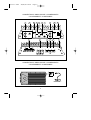
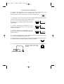
Gain Control Input External Bass Control Amp - Filter Control - Pre Output Mode Pre Output
Flat Low High
30 600
Hz
Low-pass Hi-pass
1 2 3 4 5 6 7
8
15
16
CONNECTIONS / ANSCHLUSSE / CONNEXIONES /
COLLEGAMENTI / CONEXIONES
Low Only
External Bass Control
OnOff
MinMax
Peak
CONNECTIONS / ANSCHLUSSE / CONNEXIONES /
COLLEGAMENTI / CONEXIONES
EBC
O/M ST 2.100x 25/06/02 18:23 Page 3

III
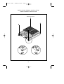
INSTALLATION / EINBAU / INSTALLATION /
INSTALLAZIONE / INSTALACION
Self Screwing scerw
O/M ST 2.100x 25/06/02 18:23 Page 4

31
ESPECIFICACIONES TECNICAS.
Potencia IHF 202 500W
Potencia RMS a (12,5 Voltios DC)
a 1 kHz < 0.08% THD+N a 4 ohms 2 x 100W
a 1 kHz<0.5% THD+N a 2 ohms 2 x 200W
a 1 kHz< 0.5% THD+N Mono a 4 ohms 1 x 400W
Sensibilidad de salida Pre-Output 2V
Pasa alto (30-600) Hz
Pasa bajo (30-600)Hz
Inclinación de cruce 12 dB/Octave
Respuesta en frecuencia+/- 1 dB 10 – 50.000 Hz
Distorsión armónica total 0.08%
Relación Señal-Ruido pesado IHF A > 100 dB
Sensibilidad de entrada – Impedancia 200-4000 mV/22 komhs
Impedancia de altavoces
Estéreo Min. 2 Ohms
Mono Min. 4 Ohms
Alimentación 14,4 V DC (11 – 16 V admitidos)
Peso 4,7 Kgg
Tamaño 212(L) x 67(A) x 405(P) mm
Debido a las continuas mejorías aportadas al producto, sus características y diseño pueden
verse sometidos a variaciones sin preaviso.
O/M ST 2.100x 25/06/02 18:23 Page 5

6
INTRODUCTION
Macrom, who strive continually to achieve the ultimate in sound quality, have traditionally
been a synonym for the very best in European sound and music reproduction. The fact that
you have chosen this product means that you share our opinion. After reading this manual you
will be in an even better position to appreciate all the advanced features in this new Amplifier.
This Amplifier incorporates an exceptional set of technical features, and for this reason all
signal sources, loudspeakers and interconnecting elements must also be of the very highest
quality. We recommend the use of Macrom high quality main subassemblies, electronic
crossovers, loudspeaker systems, connecting leads and accessories. Similarly, because
integration of these products is an extremely complex task, we advise you to leave the
installation of this amplifier to your authorised MACROM dealer.
This Amplifier has no commands or controls that can be adjusted by the user, so read this
manual very carefully, to familiarise yourself with the special features and functions of your
new MACROM product. If in any doubt, contact your authorised MACROM dealer.
PRECAUTIONS
1. Just one faulty connection could damage the unit, so read the connection instructions
provided in this manual very carefully.
2. Connect the battery lead to the (+) battery terminal last of all, and only after having
completed and checked all the other connections.
3. Take care to install the amplifier in a position where both good air circulation and heat
dissipation are guaranteed.
4. The fuses must always be replaced with fuses of identical ampere rating in order to
prevent serious damage to the components. You should also first have the voltage
regulator of your car checked. Never attempt to repair the unit yourself. Entrust any
necessary repairs to a MACROM distributor or your local MACROM service centre.
5. To ensure the highest possible performance from this unit, try to obtain a temperature of
between -10°C and +60°C inside your car before switching on the amplifier.
FEATURES
•Input mode selector
• Flat, low-pass or high-pass filter selector
• Pre-output with “Flat, High or Low-Pass Filter” selector
• Continuous external control of the low frequency gain
• Peak noise detector
• Continuous frequency control
• Continuous sensitivity control
• Current feed with Mos-Fet
•"Check Control" status indicator
•Remote-controlled start and stop
• Gold-plated RCA input terminals
• Professional gold-plated screw-type terminals
O/M ST 2.100x 25/06/02 18:23 Page 6

7
CONTROLS AND INDICATORS
1 • RCA input connectors: To connect the Pre output leads of the main unit to the amplifier
input. These inputs control the final stages.
2 • Adjustment of the gain of the Input: Adjusts input sensitivity of amplifier,
which can vary between 200 mV and 4V.
To adjust sensitivity, proceed as follows:
a)Set the volume control of your unit to 3/4 of its maximum output
b)Adjust the amplifier input gain controls until the maximum possible acoustic
pressure has been obtained without any distortion.
3 • Stereo/Mono switch: changes the output mode of the amplifier between
Stereo and Mono. If Mono is selected, the corresponding Left (mono) input is
used to operate the amplifier.
4 • Crossover switch: selects the output mode of the amplifier by activating the Low-pass or
High-pass filter.
a)Flat: the amplifier will reproduce the complete audio
range in relation to the signal applied to the input.
b)Low-pass: activation of the low-pass filter, i.e.
determination of the finishing-point of the low frequencies
present at the outputs .
c)High-pass: activation of the low-pass filter, i.e.
determination of the starting-point of the high frequencies
present at the outputs.
5 • Continuous adjustment/control of the Low-Pass or High-Pass frequencies: once the
low-pass or high-pass filter is inserted, the crossover frequency can be
adjusted in continuous mode between 30 Hz and 600 Hz.
STL(mono)
4V 0,2V
30
600
Hz
35
40
50
60
80
125
300
Flat Low High
20Hz 20kHz
Flat Low High
20Hz 30 > 600Hz
Flat Low High
20kHz30 > 600Hz
O/M ST 2.100x 25/06/02 18:23 Page 7

8
CONTROLS AND INDICATORS
6 • Continuous adjustment of the Pre-output Low-Pass or High-Pass frequencies: once
the high-pass or low-pass filter is inserted, the crossover frequency can be
adjusted between 30 Hz and 600 Hz in continuous mode.
7 • Pre-output Crossover selector: selects the Pre-output mode, activating the Low-Pass or
High-Pass filter.
a) Flat: a signal will be present on the Pre-output, in
relation to the signal applied at the input of the amplifier.
b) Low-Pass: activation of the low-pass filter, i.e.
determination of the finishing-point of the low frequencies
present at the Pre-output Outputs.
c) High-pass: activation of the low-pass filter, i.e.
determination of the starting-point of the high frequencies
present at the Pre-output Outputs.
8 • Pre-output Output Connector: it is possible to connect a supplementary amplifier for use
according to a previously selected mode.
15 • Selector switch for the External Low Frequency Control: this
switch activates or deactivates the external control of the low
frequencies.
16 • Port for EBC connection: By means of the appropriate EBC control
it is possible to act on the level of the
low frequencies between 0dB and -
40dB.
30
600
Hz
35
40
50
60
80
125
300
Flat Low High
20Hz 20kHz
Flat Low High
20Hz 30 > 600Hz
Flat Low High
20kHz30 > 600Hz
OnOff
External Bass Control
External Bass Control
Min Max
Peak
O/M ST 2.100x 25/06/02 18:23 Page 8

9
CONTROLS AND INDICATORS
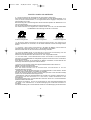
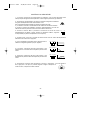
9 • Speaker connectors: Outputs for connecting the loudspeakers.
The amplifier allows the loudspeakers to be connected with a minimum impedance of 2 Ohm
for a channel in stereo configuration, and with an impedance of 4 Ohm for a "bridged" mono
connection.
If the 3 channel configuration is to be used, the total impedance should not exceed the
minimum value of 2 Ohm.
Make sure that the polarity of the connection between the loudspeakers is correct. Do not
allow inadequately insulated leads to come into contact with Ground,
any metallic parts of the car, or with each other.
10 • Fuses: When replacing fuses, make sure that they are replaced with fuses of the same
ampere rating. Use of the wrong type of fuse could seriously damage the components.
11 • + BATT connector: Connect the positive "+" of the battery directly, by means of a fuse
located nearby, and use a lead having a sufficiently large cross-section to allow passage of the
current. Do not connect this terminal to the car's own electrical circuit.
12 • REMOTE-ON connector: Connect this to the remote-on start-up output lead (remote
starting switch) or to the automatic antenna wire running from the main unit. It will now be
possible to turn the amplifier on and off from the main unit.
13 • GND connector: Attach this Ground connector, using a lead of adequate section, to a
clean point on any metallic part of the car chassis, if possible to an already-installed screw.
Never attach this clamp directly to the negative point of the battery, which could give rise to an
unpleasant buzzing noise while the car is being driven.
14 • Check control indicator: This LED indicates the amplifier functioning status.
WHITE: The unit is switched off
GREEN: The amplifier is functioning perfectly
RED: the unit is in a state of protection.
The amplifier is equipped with three protection devices:
- Overheating: If errors have been made during installation, and the amplifier overheats, the
unit will enter into a state of protection before any damage can occur. Once the temperature
returns to normal and the errors have been rectified, the unit will automatically start to function
normally once again.
- Overloading: If several loudspeakers have been connected to the amplifier and the total
impedance drops below the 1 Ohm limit that it can handle, the amplifier goes into a state of
protection. The main unit will have to be switched off and on again in order to restore the
amplifier to normal functioning.
- Short circuit in an output: In the case of a short circuit in the loudspeaker outputs, the unit will
go into a state of protection to avoid serious damage to the final transistors. Normal
functioning will be restored when the short circuit has been dealt with and the main unit
switched on again.
RL
Bridged
RL
Bridged
RL
Bridged
3-channel configuration 2-channel configuration 1-channel configuration
O/M ST 2.100x 25/06/02 18:23 Page 9

10
TECHNICAL DATA
Power IHF 202 500W
RMS Power at (12.5 Volts DC)
at 1 kHz < 0.08 % THD+N at 4 Ohm 2 x 100W
at 1 kHz < 0.5 % THD+N at 2 Ohm 2 x 200W
at 1 kHz < 0.5 % THD+N Mono at 4 Ohm 1 x 400W
Pre-Out Sensitivity 2V
High pass control, (30-600) Hz
Low pass control, (30-600) Hz
Crossover slope 12 dB/Octave
Response in frequency +/- 1 dB 10 - 50.000 Hz
Total harmonic distortion 0.08%
Weighted IHF A Signal-Noise Ratio > 100 dB
Input sensitivity - Impedance 200-4000 mV/22 kOhm
Loudspeaker impedances
Stereo min. 2 Ohms
Mono min. 4 Ohms
Power supply 14.4 V DC (11 - 16 V permissible)
Weight 4,7 kgrs
Dimensions 212(L) x 67(A) x 405(P) mm
Due to the continual incorporation of improvements in this product, the characteristics and
design may be subject to variation without prior notice.
O/M ST 2.100x 25/06/02 18:23 Page 10

11
EINFÜHRUNG
Macrom ist seit jeher Synonym für europäische Tradition auf dem Sektor der Akustik und
Musikwiedergabe und bestrebt, mit ihren Geräten nur höchste Klangqualität zu bieten.
Die Tatsache, daß Sie sich für dieses Produkt entschieden haben, bedeutet, daß Sie ebenso
denken.
Dieses Handbuch soll Ihnen dabei helfen, sich mit den fortgeschrittenen Merkmalen dieser
neuen Endstufe vertraut zu machen.
Diese Endstufe schließt eine Reihe beachtlicher technischer Merkmale ein, die höchste
Qualität von allen Tonquellen, Lautsprechern und angeschlossenen Geräten erfordern.
Wir empfehlen die Verwendung von Head-Units, elektronischen Frequenzweichen,
Lautsprechersystemen, Anschlußkabeln und hochwertigen Zubehörteilen von MACROM. Da
die Integration dieser Produkte sehr komplex ist, raten wir Ihnen, die Installation von Ihrem
MACROM-Vertragshändler vornehmen zu lassen.
Diese Endstufe hat keine vom Anwender einstellbare Steuerungen; lesen Sie dieses
Handbuch aufmerksam durch, um sich mit den besonderen Merkmalen und Funktionen Ihres
neuen Macrom-Produkts vertraut zu machen.
Wenden Sie sich für jedes Problem vertrauensvoll an Ihren MACROM-Vertragshändler.
VORSICHTSMAßNAHMEN
1. Jegliche falsche Verbindung könnte das Gerät beschädigen. Lesen Sie aufmerksam die
Anleitungen für den Kabelanschluß durch.
2. Das Batteriekabel zuletzt an den Pluspol (+) der Batterie anschließen und nur, nachdem
alle anderen Anschlüsse ausgeführt worden sind.
3. Man vergewissere sich, daß die elektronische Frequenzweiche an einer Stelle installiert
wird, wo gute Luftzirkulation und eine gute Wärmeabgabe gewährleistet sind.
4. Die Sicherungen müssen immer durch Sicherungen mit der gleichen Amperezahl ersetzt
werden, um schwere Beschädigungen der Gerätekomponenten zu vermeiden. Man lasse
bei mehrmaligem Durchbrennen der Sicherungen die Lichtmaschine des Wagens
überprüfen. Das Gerät niemals selber reparieren, sondern jegliche Reparatur Ihrem
MACROM-Vertragshändler oder der nächsten MACROM-Dienststelle übergeben.
5. Um die besten Leistungen zu erzielen sollte die Temperatur im Wageninnenraum zwischen
-10° C und +60° C liegen, bevor man das Gerät einschaltet.
EIne gute Lüftung des Wageninnenraums ist erforderlich, um die Überhitzung der inneren
Stromkreise des Gerätes zu vermeiden.
EIGENSCHAFTEN
• Eingangsmodus-Wahlschalter
•Wahlschalter des Filters , flat, low-pass oder high-pass
• Stufenlose Einstellung der Frequenz
• Stufenlose Einstellung der Empfindlichkeit
•Vorausgang mit Flat-, High-Oder Low-Pass-Filter-Einstellung
• Äußere, stufenlose Einstellung des Gewinns der tiefen Frequenzen
• Spitzenwertanzeige
• MOS-FET-Netzteil
•Statusanzeige "Check Control"
• Ein- und Ausschalten über Remote-Leitung
•Vergoldete RCA-Eingangskontakte
•Professionelle vergoldete Schraubkontakte
O/M ST 2.100x 25/06/02 18:23 Page 11

12
KONTROLLEN & ANZEIGEN
1 • RCA-Eingangskontakte: Damit können die Pre-Ausgangskabel der Head-Unit an den
Eingang des Verstärkers angeschlossen werden. Diese Eingänge steuern die Endstufen.
2 •Einstellung des Eingangsgewinns: Ermöglicht die Einstellung der
Eingangsempfindlichkeit der Endstufe zwischen 200 mV und 4V.
Zur Einstellung der Empfindlichkeit, folgendermaßen vorgehen:
a) Den Lautstärkeregler Ihres Geräts auf 3/4 des maximalen Pegels einstellen.
b) Die Gewinnsteuerung der Endstufe so einstellen, daß man den maximalen
Schalldruck ohne Verzerrung erhält.
3 • Wahlschalter Stereo/Mono: Er ermöglicht die Stereo- oder Mono-Auswahl
des Ausgangsmodus der Endstufe. Bei Auswahl des Mono-Ausgangsmodus muß
zum Ansteuern der Endstufe der Eingang LEFT (Mono) verwendet werden.
4 • Wahlschalter der Frequenzweiche: Ermöglicht die Auswahl des Ausgangsmodus der
Endstufe durch Aktivierung des Low-Pass oder High-Pass-Filters.
a) Flat: Die Endstufe gibt den gesamten Frequenzbereich
des am Eingang angelegten Signals wieder.
b) Low-Pass: Aktivierung des Tiefpaß-Filters, d. h., das
Ende der am Eingang anliegenden Niederfrequenzen wird
bestimmt.
c) High-Pass, Aktivierung des Tiefpaß-Filters, d. h. man
bestimmt den Anfang der an den Eingängen anliegenden
hohen Frequenzen.
5 • Stufenlose Regelung der Low-Pass oder High-Pass Frequenzen: Nach Zuschalten
des High-Pass oder Low-Pass-Filters ist es möglich, den Frequenzübergang
stufenlos zwischen 30 Hz und 600 Hz einzustellen.
STL(mono)
4V 0,2V
30
600
Hz
35
40
50
60
80
125
300
Flat Low High
20Hz 20kHz
Flat Low High
20Hz 30 > 600Hz
Flat Low High
20kHz30 > 600Hz
O/M ST 2.100x 25/06/02 18:23 Page 12

13
KONTROLLEN & ANZEIGEN
6 •Stufenlose Einstellung der Pre-output Low-Pass oder High Pass-Frequenzen : nach
Einschalten des High-Pass oder Low-Pass-Filters kann die
Übergangsfrequenz stufenlos zwischen 30 Hz und 600 Hz geregelt werden.
7 •Wahlschalter der Pre-output-Frequenzweiche: ermöglicht die Auswahl des Pre-output-
Modus durch Aktivierung des Low-Pass oder High-Pass-Filters.
a) Flat: Am Pre-output-Ausgang wird ein dem am
Endstufeneingang angelegten Signal entsprechendes
Signal anliegen.
b) Low-Pass: Aktivierung des Tiefpaß-Filters, d. h. man
bestimmt das Ende der tiefen, an den Eingängen
anliegenden Frequenzen.
c) High-Pass, Aktivierung des Tiefpaß-Filters, d. h. man
bestimmt den Anfang der an den Eingängen anliegenden
hohen Frequenzen.
8 • Pre-output-Ausgangskontakt: Eine zusätzliche Endstufe kann angeschlossen werden,
die im vorher ausgewählten Modus betrieben wird.
15 •Wahlschalter für die äußere Kontrolle der Bässe: Ermöglicht das
Ein- oder Ausschalten der äußeren Einstellung der tiefen Frequenzen.
16 • Port für den Anschluß der EBC: Über die EBC-Kontrolle kann man
das Niveau der tiefen Frequenzen
zwischen 0dB und -40dB
einstellen.
30
600
Hz
35
40
50
60
80
125
300
Flat Low High
20Hz 20kHz
Flat Low High
20Hz 30 > 600Hz
Flat Low High
20kHz30 > 600Hz
OnOff
External Bass Control
External Bass Control
Min Max
Peak
O/M ST 2.100x 25/06/02 18:23 Page 13

14
EINSTELLUNGEN UND ANZEIGEN
9 • Lautsprecheranschluß: Ausgänge für den Anschluß der Lautsprecher.
Die Endstufe ermöglicht den Anschluß von Lautsprechern mit einer Mindestimpedanz von 2
Ohm pro Kanal im Stereo-Modus, im mono-gebrückten Modus dagegen Lautsprecher mit
einer Impedanz von 4 Ohm.
Bei Verwendung der 3-Kanal-Konfiguration darf die Gesamt-Impedanz den Mindestwert von 2
Ohm nicht übersteigen.
Auf die richtige Polarität beim Anschluß der Lautsprecher achten.
Der Kontakt zwischen nicht angemessen isolierten Kabeln unter sich, mit dem Massekabel
und Metallteilen des Fahrzeugs ist absolut zu vermeiden.
10 • Sicherung: Beim Auswechseln der Sicherung darauf achten, eine Sicherung mit
derselben Amperezahl zu verwenden, da die Geräte andernfalls schwer beschädigt werden
können.
11 • Anschluß + BATT: Über eine Sicherung in der Nähe der Batterie und ein Kabel mit
angemessenem Querschnitt direkt an den "+"-Pol der Batterie anschließen.
Diesen Anschluß nicht mit dem Stromkreis des Fahrzeugs verbinden.
12 • Anschluß REMOTE-ON: An die Remote-on-Leitung der Fernsteuerung oder der
elektrischen Antenne anschließen, die von der Head-Unit kommt.
Dadurch kann die Endstufe über die Head-Unit ein- bzw. ausgeschaltet werden.
13 • Anschluß GND: Diese Masseklemme mittels eines Kabels mit entsprechendem
Querschnitt an eine Metallstelle des Fahrgestells möglichst mit Hilfe einer schon vorhandenen
Schraube anschließen.
Diese Klemme nie direkt an den Minuspol der Batterie anschließen, da beim Betrieb des
Fahrzeugs störende Summgeräusche auftreten können.
14 •Check control-Anzeige: Diese LED zeigt den Betriebszustand der Endstufe an.
WEISS: Das Gerät ist ausgeschaltet
GRÜN: Das Gerät funktioniert einwandfrei.
ROT: Das Gerät befindet sich im Schutzzustand; diese Endstufe ist mit drei
Schutzeinrichtungen versehen:
- Überhitzung: Sollte die Endstufe aufgrund von Installationsfehlern zu heiß werden, schaltet
das Gerät in den Schutzbetrieb, um Schäden zu vermeiden.
Sobald die Temperatur wieder auf einen normalen Wert gesunken ist und die Fehler beseitigt
worden sind, wird der Betrieb wieder aufgenommen.
- Überbelastung: Sollte die Gesamtimpedanz bei Anschluß von mehreren Lautsprechern an
die Endstufe unter den Grenzwert von 1 Ohm sinken, schaltet die Endstufe in den
Schutzbetrieb.
Die Wiederherstellung des normalen Betriebs erhält man durch Aus- und anschließendes
Wiedereinschalten der Head-Unit.
- Kurzschluß am Ausgang: Im Fall von Kurzschlüssen an den Lautsprecherausgängen tritt
des Gerät in den Schutzstatus, um die Beschädigung der Endstufentransistoren zu
vermeiden.
Die Wiederherstellung des normalen Betriebs erhält man nach Beseitigung des Kurzschlusses
RL
Bridged
RL
Bridged
RL
Bridged
3-channel configuration 2-channel configuration 1-channel configuration
O/M ST 2.100x 25/06/02 18:23 Page 14

15
TECHNISCHE DATEN
Leistung IHF 202 500W
RMS-Leistung bei (12,5 Volt DC)
bei 1 kHz < 0,08 % THD+N bei 4 Ohm 2 x 100W
bei 1 kHz < 0,5 % THD+N bei 2 Ohm 2 x 200W
bei 1 kHz < 0,5 % THD+N Mono bei 4 Ohm 1 x 400W
Vorausgangsempfindlichkeit 2V
Hochpaß-Einstellung (30-600)Hz
Tiefpaß-Einstellung (30-600)Hz
Flankensteilheit 12 dB/Oktave
Frequenzgang +1 dB 10-50.000 Hz
Harmonische Verzerrung, gesamt 0,08%
Rauschabstand, IHF A-gewichtet > 100 dB
Eingangsempfindlichkeit – Impedanz 200-4000 mV/22 kOhm
Lautsprecherimpedanz
Stereo min. 1 Ohm
Mono min. 2 Ohm
Stromversorgung 14,4 V DC (11 - 16 V zulässig)
Gewicht 4,7 kg
Maß 212(L) x 67(H) x 405(T) mm
Änderungen der technischen Daten und des Design bleiben zwecks Verbesserung
vorbehalten.
O/M ST 2.100x 25/06/02 18:23 Page 15

16
INTRODUCTION
Macrom est depuis toujours le synonyme de la tradition européenne acoustique et musicale,
à la recherche de la meilleure qualité sonore. Le fait que vous ayez choisi ce produit signifie
que vous aussi, vous êtes d’accord avec nous. Avec l’aide de ce manuel d’instruction, vous
allez pouvoir apprécier toutes les caractéristiques technologiques avancées de ce nouvel
amplificateur.
Cet amplificateur a des caractéristiques techniques spéciales, il est donc important que toutes
les sources de signaux, les haut-parleurs et les autres appareils d’interconnexion soient de
très bonne qualité. Nous vous recommandons d’utiliser des unités principales, des crossover
électroniques, des systèmes de haut-parleurs, des fils de connexion et les accessoires de
hautes qualité de la marque MACROM. Vu que l’intégration de ces produits est très complexe,
nous vous conseillons de faire installer cet amplificateur par un revendeur autorisé MACROM.
Cet amplificateur n’a pas de commandes ni de contrôles réglables par l’utilisateur. Lisez
attentivement ce manuel d’instruction pour vous familiariser avec toutes les caractéristiques
spéciales et les fonctions de votre nouveau modèle MACROM. En cas de doute, adressez-
vous à votre revendeur autorisé MACROM.
PRECAUTIONS
1. Toute mauvaise connexion des fils pourrait endommager votre unité. Lire attentivement
les instructions données dans ce manuel pour une correcte connexion des fils.
2. Il faut relier le fil de la batterie au terminal (+) de la batterie même en dernier et seulement
après avoir terminé et contrôlé toutes les autres connexions.
3. Assurez-vous d’installer votre amplificateur dans une position qui garantisse une bonne
circulation d’air et une bonne dispersion de la chaleur.
4. Les fusibles doivent toujours être remplacer par des fusibles de même ampérage pour
éviter que les composants ne soient gravement endommagés. De plus, faites contrôler le
voltage de votre voiture. Evitez de réparer vous-même votre appareil. Confiez la
réparation éventuelle au distributeur MACROM ou bien au centre d’assistance MACROM
de la zone.
5. Pour assurer les meilleures performances de votre unité, ayez soin que la température à
l’intérieur de la voiture soit comprise entre -10°C et +60°C avant d’allumer l’appareil.
CARACTERISTIQUES
• Sélecteur du mode d’entrée
• Sélecteur du filtre, Flat, Low-Pass ou High-Pass
• Pre-Sortie avec sèlecteur “Flat,high ou Low-Pass Filter”
• Réglage externe continu du gain des basses fréquences
• Révélateur de pics
• Réglage continu de la fréquence
• Réglage continu de la sensibilité
•Alimentation à Mos-Fet
•Indicateur d’état « Check Control »
•Allumage à distance
• Connecteurs d’entrée RCA dorés
O/M ST 2.100x 25/06/02 18:23 Page 16

17
CONTROLES ET INDICATEURS
1 • Connecteurs d’entrée RCA : ils permettent de relier les fils de sortie Pré de votre unité
principale à l’entrée de l’amplificateur. Ces entrées piloteront les étages finals.
2 • Réglage du gain à l’entrée : cela permet de régler la sensibilité d’entrée de
l’amplificateur qui varie de 200 mV à 4 V.
Pour le réglage de la sensibilité, suivre les instructions suivantes :
a) Régler le contrôle du volume de votre unité au _ de la sortie maximale.
b) Tourner le contrôle du gain d’entrée de l’amplificateur de façon à obtenir le
niveau sonore maximum mais sans aucune distorsion.
3 • Sélecteur Stéréo Mono : il permet de sélectionner la sortie stéréo ou mono
de l’amplificateur. En cas d’utilisation mono, l’entrée correspondante pour piloter
l’amplificateur est Left (mono).
4 • Sélecteur du Crossover : cela permet de sélectionner le mode de sortie de
l’amplificateur en activant le filtre Low-Pass ou bien High-Pass.
a) Flat : l’amplificateur va reproduire toute la gamme audio
en relation au signal appliqué à son entrée.
b) Low-Pass : mise en fonction du filtre passe bas, c’est à
dire, déterminer la fin des basses fréquences présentes
aux sorties Front.
c) High-Pass, mise en fonction du filtre passe basse, c’est
à dire déterminer le départ des hautes fréquences
présentes aux sorties Front.
5 • Réglage continu des fréquences Low-Pass ou High-Pass. : une fois que le filtre High-
Pass ou Low-Pass a été sélectionné, on peut régler la fréquence de coupe,
comprise entre 30 Hz et 600 Hz, de façon continue.
STL(mono)
4V 0,2V
30
600
Hz
35
40
50
60
80
125
300
Flat Low High
20Hz 20kHz
Flat Low High
20Hz 30 > 600Hz
Flat Low High
20kHz30 > 600Hz
O/M ST 2.100x 25/06/02 18:23 Page 17

18
CONTROLES ET INDICATEURS
6 • Réglage continu des fréquences Low-Pass ou High-Pass. Pre-output : après avoir
introduit le filtre High-Pass ou Low-Pass, on peut régler la fréquence de
coupe, comprise entre 30 Hz et 600 Hz de façon continue.
7 • Sélecteur du Crossover Pre-output : il permet de sélectionner le mode de sortie Pré en
activant le filtre Low-Pass ou High-Pass.
a) Flat : à la sortie Pré on trouvera un signal en relation
au signal appliqué à l’entrée de l’amplificateur.
b) Low-Pass : activation du filtre passe bas, c’est à dire,
déterminer la fin des basses fréquences présentes aux
sorties Front.
c) High-Pass, activation du filtre passe bas, c’est à dire
déterminer le départ des hautes fréquences présentes aux
sorties Front.
8 • Connecteur de sortie Pré: il est possible de relier un amplificateur supplémentaire qui
sera utilisé dans le mode sélectionné auparavant.
17 •Sélecteur pour le contrôle externe des basses : il permet d’activer
et de désactiver le contrôle externe des fréquences basses.
18 •Port pour la connexion EBC : par l’intermédiaire du contrôle EBC,
on peut intervenir sur le niveau des
fréquences basses entre 0 dB et -40
dB.
30
600
Hz
35
40
50
60
80
125
300
Flat Low High
20Hz 20kHz
Flat Low High
20Hz 30 > 600Hz
Flat Low High
20kHz30 > 600Hz
OnOff
External Bass Control
External Bass Control
Min Max
Peak
O/M ST 2.100x 25/06/02 18:23 Page 18

19
CONTROLES ET INDICATEURS
11 •Connecteurs speakers : sorties pour la connexion des haut-parleurs.
L’amplificateur permet de relier les haut-parleurs avec une impédance minimum de 2 Ohm par
canal en stéréo, alors qu’en mono ponté l’impédance est de 4 Ohm.
Dans la configuration à 3 canaux, l’impédance totale ne doit pas dépasser la valeur minimum
de 2 Ohm.
Assurez-vous de respecter la polarité correcte pour relier les haut-parleurs. Ne permettez pas
aux fils non isolés d’entrer en contact entre eux ou avec le fil de mise à
terre ou les parties métalliques de la voiture.
12 •Fusible : si les fusibles doivent être changés, il faut s’assurer qu’ils soient remplacés avec
des fusibles de même ampérage. L’utilisation de fusibles avec un autre ampérage pourrait
endommager gravement les composants de l’appareil.
13 •Connecteurs +BATT : relier directement au positif « + » de la batterie, en interposant un
fusible le plus près possible, avec un câble de section adéquate. Il ne faut pas relier ce
terminal au circuit électrique de la voiture.
14 •Connecteur REMOTE-ON : relier au fil de sortie de l’allumage remote-on (allumage à
distance) ou au fil de commande de l’antenne automatique provenant de l’unité principale.
Ceci permet d’allumer et d’éteindre l’amplificateur par l’intermédiaire de l’unité principale.
15 •Connecteurs GND : relier ce connecteur de masse avec un fil de section adéquate à un
point propre sur la partie métallique du châssis de la voiture, si possible à une vis déjà
installée.
Il ne faut en aucun cas relier ce connecteur directement au pôle négatif de la batterie, cela
pourrait causer un grésillement désagréable pendant le fonctionnement de la voiture.
16 •Indicateur check control : ce led indique l’état de fonctionnement de l’amplificateur.
BLANC : l’unité est éteinte.
VERT : l’unité fonctionne parfaitement.
ROUGE : l’unité est en état de protection, cet amplificateur est pourvu de trois protections :
Surchauffe : en cas d’erreurs d’installation provoquant une surchauffe de l’amplificateur, l’unité
entre en état de protection avant de subir des dommages. Dés que la température retourne à
des valeurs normales et que les erreurs ont été éliminées, l’amplificateur reprend son
fonctionnement normal.
Surcharges : en cas où plusieurs haut-parleurs reliés à l’amplificateur et que l’impédance
totale descende en dessous des limites de tolérance de 1 Ohm, l’amplificateur entre en état
de protection. Pour remettre en état de fonctionnement l’amplificateur, il suffit d’éteindre et de
rallumer l’unité principale.
Court-circuit à la sortie : en cas de court-circuit à la sortie des haut-parleurs, l’unité entre en
état de protection pour prévenir de sérieux dommages aux transistors finals. Elle retourne à
l’état de fonctionnement normal lorsque le court-circuit est éliminé et l’unité principale
rallumée.
RL
Bridged
RL
Bridged
RL
Bridged
3-channel configuration 2-channel configuration 1-channel configuration
O/M ST 2.100x 25/06/02 18:23 Page 19

20
DONNEES TECHNIQUES
Puissance IHF 202 500W
Puissance RMS à (12,5 Volts cc)
à 1 kHz < 0,08% THD+N à 4 Ohm 2 x 100W
à 1 kHz < 0,5 % THD+N à 2 Ohm 2 x 200W
à 1 kHz < 0,5 % THD+N mono à 4 Ohm 1 x 400W
Sensibilité de sortie Pre-Output 2V
Contrôle Passe haut (30-600) Hz
Contrôle Passe bas (30- 600) Hz
Pente de coupe 12 dB/Octave
Réponse en fréquence +/- 1 dB 10 –50.000 Hz
Distorsion harmonique totale 0,08%
Rapport signal/ bruit, pesé IHF A >100 dB
Sensibilité d’entrée - Impédance 200-4000 mV/22 kOhm
Impédance des haut-parleurs
Stéréo min. 1 Ohm
Mono min. 2 Ohm
Alimentation 14,4 V cc (11 – 16 V admis)
Poids 4,7 kg
Dimensions 212(L) x 67(H) x 405(P) mm
En raisons des améliorations continues apportées au produit, les caractéristiques et le dessin
sont sujets à des modifications sans préavis.
O/M ST 2.100x 25/06/02 18:23 Page 20
La pagina si sta caricando...
La pagina si sta caricando...
La pagina si sta caricando...
La pagina si sta caricando...
La pagina si sta caricando...
La pagina si sta caricando...
La pagina si sta caricando...
La pagina si sta caricando...
La pagina si sta caricando...
La pagina si sta caricando...
-
 1
1
-
 2
2
-
 3
3
-
 4
4
-
 5
5
-
 6
6
-
 7
7
-
 8
8
-
 9
9
-
 10
10
-
 11
11
-
 12
12
-
 13
13
-
 14
14
-
 15
15
-
 16
16
-
 17
17
-
 18
18
-
 19
19
-
 20
20
-
 21
21
-
 22
22
-
 23
23
-
 24
24
-
 25
25
-
 26
26
-
 27
27
-
 28
28
-
 29
29
-
 30
30


Macrom 2.100x Manuale utente
- Categoria
- Amplificatori audio per auto
- Tipo
- Manuale utente
- Questo manuale è adatto anche per
in altre lingue
- English: Macrom 2.100x User manual
- français: Macrom 2.100x Manuel utilisateur
- español: Macrom 2.100x Manual de usuario
- Deutsch: Macrom 2.100x Benutzerhandbuch