
ELECTRONICS FOR SPECIALISTS ELECTRONICS FOR SPECIALISTS ELECTRONICS FOR SPECIALISTS ELECTRONICS FOR SPECIALISTS ELECTRONICS FOR SPECIALISTS ELECTRONICS
MONACOR INTERNATIONAL GmbH & Co. KG • Zum Falsch 36 • 28307 Bremen • Germany
Copyright
©
by MONACOR INTERNATIONAL. All rights reserved.
A-0681.99.03.07.2016
LINE IN
LINE IN
ISO OUT
1
ISO OUT
1
DIRECT OUT
DIRECT OUT
ISO OUT
2
ISO OUT
2
LSP-102
A
B
LIFT
GND
LIFT
GND
LIFT
GND
LIFT
GND
41 2
43 3
1 2
4 43 3
1
2
3
1
2
3
LINE IN ISO OUT 1
LIFT
GND
1
2
3
ISO OUT 2
1
2
3
DIRECT
OUT
LIFT
GND
LSP-102 Bestell-Nr. • Order No. 25.1680
2-Channel Line Splitter
These instructions are intended for users
without any specific technical knowledge.
Please read these instructions carefully prior
to operating the unit and keep them for later
reference.
1 Applications
The LSP-102 has been designed to split one line
signal to several outputs. It has two independent
signal ways (A and B) so that e. g. the stereo output
of a mixer may be connected to the stereo inputs of
two amplifiers and one recorder. For decoupling the
two outputs, the signals are led via special audio
transformers and are thus galvanically isolated. In
addition, a feed-through output is provided which
is directly connected to the input.
The signal ground of the decoupled outputs
can in each case be separated by switch from the
ground of the input. Thus, a ground loop which
may cause an interfering hum noise can be inter-
rupted. It occurs e. g. when the connect ed units
have contact in the rack both via the signal ground
and via the earthed conductor of the power supply
or a conductive connection of the housings.
2 Important Notes
The unit corresponds to all relevant directives of the
EU and is therefore marked with
.
•
The unit is suitable for indoor use only. Protect it
against dripping water and splash water, high air
humidity and heat (admissible ambient tempera-
ture range 0 – 40 °C).
•
For cleaning only use a dry, soft cloth; never use
chemicals or water.
•
No guarantee claims for the unit and no liability
for any resulting personal damage or material
damage will be accepted if the unit is used for
other purposes than originally intended, if it is
not correctly connected or operated or if it is not
repaired in an expert way.
If the unit is to be put out of operation
definitively, take it to a local recycling plant
for a disposal which is not harmful to the
environment.
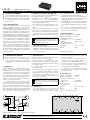
3 Connections
1) To prevent switching noise, first switch off the
units to be connected to the outputs, or mute
their inputs or attenuate the output level them.
2) Connect the outputs of the audio sources to the
input jacks LINE IN (1).
3) Connect the inputs of the audio units to be
directly connected (e. g. amplifier, further LSP-
102 units) to the outputs DIRECT OUT (2).
4) Connect the inputs of the following audio units
to be decoupled (e. g. amplifier, mixer) to the
corresponding outputs ISO OUT (3).
5) If required, set the corresponding ground lift
switch (4) from position GND to position LIFT
(grounds separated).
4 Specifications
Optimum source impedance: � � 50 – 600 Ω
Optimum load impedance: � � � � ≥ 5 kΩ
Characteristics of the transformer
frequency range: � � � � � � � � � � 20 – 20 000 Hz
impedance: � � � � � � � � � � � � � 600 Ω at 1 kHz
max� input voltage
at 40 Hz, THD < 1 %: � � � � � � 5 V
Dimensions:
� � � � � � � � � � � � � � 160 × 55 × 105 mm
Weight: � � � � � � � � � � � � � � � � � � 980 g
Subject to technical modification.
2-Kanal-Line-Splitter
Diese Bedienungsanleitung richtet sich an Be-
nutzer ohne besondere Fachkenntnisse. Bitte
lesen Sie die Anleitung vor dem Betrieb gründ-
lich durch und heben Sie sie für ein späteres
Nachlesen auf.
1 Einsatzmöglichkeiten
Der LSP-102 ist dafür konzipiert, ein Line-Signal auf
mehrere Ausgänge zu verteilen. Er hat zwei un-
abhängige Signalwege (A und B), sodass z. B. der
Stereo-Ausgang eines Mischpults mit den Stereo-
Eingängen zweier Verstärker und eines Recorders
verbunden werden kann. Zur Entkopplung der bei-
den Ausgänge werden die Signale über spezielle
Audioübertrager geführt und dadurch galvanisch
getrennt. Zusätzlich ist ein Durchschleifausgang vor-
handen, der direkt mit dem Eingang verbunden ist.
Die Signalmasse der entkoppelten Ausgänge
kann jeweils per Schalter von der Masse des Ein-
gangs getrennt werden. So lässt sich eine Masse-
schleife, die ein störendes Brummen verursachen
kann, auftrennen. Sie entsteht z. B. wenn die an-
geschlossenen Geräte sowohl über die Signalmasse
als auch über den Schutzleiter der Stromversorgung
oder eine leitende Verbindung der Gehäuse im
Rack Kontakt haben.
2 Wichtige Hinweise für den Gebrauch
Das Gerät entspricht allen relevanten Richtlinien der
EU und trägt deshalb das -Zeichen.
•
Verwenden Sie das Gerät nur im Innenbereich.
Schützen Sie es vor Tropf- und Spritzwasser,
hoher Luftfeuchtigkeit und Hitze (zulässiger Ein-
satztemperaturbereich 0 – 40 °C).
•
Verwenden Sie für die Reinigung nur ein trocke-
nes, weiches Tuch, niemals Chemikalien oder
Wasser.
•
Wird das Gerät zweckentfremdet, nicht richtig
angeschlossen, falsch bedient oder nicht fach-
gerecht re pa riert, kann keine Haftung für daraus
resultierende Sach- oder Personenschäden und
keine Garantie für das Gerät übernommen wer-
den.
Soll das Gerät endgültig aus dem Betrieb
genommen werden, übergeben Sie es zur
umweltgerechten Entsorgung einem ört-
lichen Recyclingbetrieb.
3 Anschlüsse herstellen
1) Zur Vermeidung von Schaltgeräuschen die an die
Ausgänge anzuschließenden Geräte zunächst
ausschalten oder deren Eingänge stummschal-
ten oder herunterregeln.
2) Die Ausgänge der Audioquellen an die Ein-
gangsbuchsen LINE IN (1) anschließen.
3) Die Eingänge der direkt zu verbindenden Audio-
geräte (z. B. Verstärker, weitere LSP-102) an die
Ausgänge DIRECT OUT (2) anschließen.
4) Die Eingänge der zu entkoppelnden nachfolgen-
den Audiogeräte (z. B. Verstärker, Mischpult) mit
den jeweiligen Ausgängen ISO OUT (3) verbin-
den.
5) Wenn nötig, den jeweiligen Groundlift-Schalter
(4) von der Position GND auf die Position LIFT
(Massen getrennt) umschalten.
4 Technische Daten
Optimale Quellimpedanz: � � � � 50 – 600 Ω
Optimale Lastimpedanz: � � � � � ≥ 5 kΩ
Eigenschaften des Übertragers
Frequenzbereich: � � � � � � � � � 20 – 20 000 Hz
Impedanz: � � � � � � � � � � � � � � 600 Ω bei 1 kHz
Max� Eingangsspannung
bei 40 Hz, Klirrfaktor < 1 %: � 5 V
Abmessungen:
� � � � � � � � � � � � 160 × 55 × 105 mm
Gewicht: � � � � � � � � � � � � � � � � � 980 g
Änderungen vorbehalten.
DeutschEnglish
Prinzipschaltbild (1 Kanal) • Basic circuit diagram (1 channel)

ELECTRONICS FOR SPECIALISTS ELECTRONICS FOR SPECIALISTS ELECTRONICS FOR SPECIALISTS ELECTRONICS FOR SPECIALISTS ELECTRONICS FOR SPECIALISTS ELECTRONICS
MONACOR INTERNATIONAL GmbH & Co. KG • Zum Falsch 36 • 28307 Bremen • Germany
Copyright
©
by MONACOR INTERNATIONAL. All rights reserved.
A-0681.99.03.07.2016
LINE IN
LINE IN
ISO OUT
1
ISO OUT
1
DIRECT OUT
DIRECT OUT
ISO OUT
2
ISO OUT
2
LSP-102
A
B
LIFT
GND
LIFT
GND
LIFT
GND
LIFT
GND
41 2
43 3
1 2
4 43 3
1
2
3
1
2
3
LINE IN ISO OUT 1
LIFT
GND
1
2
3
ISO OUT 2
1
2
3
DIRECT
OUT
LIFT
GND
LSP-102 Réf. num. • Codice 25.1680
Splitter di linea a 2 canali
Queste istruzioni sono rivolte all’utente senza
conoscenze tecniche specifiche. Vi preghiamo
di leggerle attentamente prima della messa in
funzione e di conservarle per un uso futuro.
1 Possibilità d’impiego
L’LSP-102 è stato realizzato per distribuire un se-
gnale di linea fra varie uscite. Possiede due vie
indipendenti di segnali (A e B), in modo che per
esempio l’uscita stereo di un mixer può essere col-
legata con gli ingressi stereo di due amplificatori e
di un registratore. Per disaccoppiare le due uscite,
i segnali vengono portati attraverso dei trasforma-
tori audio speciali per una separazione galvanica. In
più esiste un’uscita passante collegata direttamente
con l’ingresso.
La massa del segnale delle uscite disaccoppiate
può essere separata dalla massa dell’ingresso per
mezzo di un interruttore. In questo modo è possi-
bile aprire un anello di terra che può provocare un
ronzio fastidioso. Tale anello si crea per esempio se
entrambe le sorgenti di segnali sono in contatto
nel rack sia attraverso la massa dei segnali che at-
traverso il conduttore di terra dell’alimentazione
oppure attraverso un collegamento conduttivo dei
contenitori.
2 Avvertenze importanti per l’uso
Quest’apparecchio è conforme a tutte le direttive
rilevanti dell’UE e pertanto porta la sigla .
•
Usare l’apparecchio solo all’interno di locali. Pro-
teggerlo dall’acqua gocciolante e dagli spruzzi
d’acqua, da alta umidità dell’aria e dal calore (tem-
peratura d’impiego ammessa fra 0 °C e 40 °C).
•
Per la pulizia usare solo un panno morbido,
asciutto; non impiegare in nessun caso prodotti
chimici o acqua.
•
Nel caso d’uso improprio, di collegamenti sba-
gliati, d’impiego scorretto o di riparazione non
a regola d’arte dell’apparecchio, non si assume
nessuna responsabilità per eventuali danni con-
sequenziali a persone o a cose e non si assume
nessuna garanzia per l’apparecchio.
Se si desidera eliminare l’apparecchio de-
finitivamente, consegnarlo per lo smalti-
mento ad un’istituzione locale per il rici-
claggio.
3 Eseguire i collegamenti
1) Per escludere rumori di collegamento conviene
spegnere dapprima gli apparecchi da collegare
con le uscite o mettere su muto o abbassare i
loro ingressi.
2) Collegare le uscite delle sorgenti audio con le
prese d’ingresso LINE IN (1).
3) Collegare gli ingressi degli apparecchio audio da
collegare direttamente (p. es. amplificatore, altri
LSP-102) con le uscite DIRECT OUT (2).
4) Collegare gli ingressi degli apparecchio audio
a valle da disaccoppiare (p. es. amplificatore,
mixer) con le relative uscite ISO OUT (3).
5) Se necessario, spostare il relativo interruttore
groundlift (4) dalla posizione GND in posizione
LIFT (masse separate).
4 Dati tecnici
Impedenza ottimale
della sorgente:
� � � � � � � � � � � � � � � � � 50 – 600 Ω
Impedenza ottimale del carico: � � � � � ≥ 5 kΩ
Caratteristiche del trasformatore
Gamma di frequenze: � � � � � � � � � � � 20 – 20 000 Hz
Impedenza: � � � � � � � � � � � � � � � � � � 600 Ω con 1 kHz
Tensione max� d’ingresso con 40 Hz,
fattore di distorsione < 1 %: � � � � � 5 V
Dimensioni: � � � � � � � � � � � � � � � � � � � � 160 × 55 × 105 mm
Peso: � � � � � � � � � � � � � � � � � � � � � � � � � 980 g
Con riserva di modifiche tecniche.
Répartiteur Ligne 2 canaux
Cette notice s’adresse aux utilisateurs sans
connaissances techniques particulières. Veuil-
lez lire la présente notice avant le fonction-
nement et conservez-la pour pouvoir vous y
reporter ultérieurement.
1 Possibilités d’utilisation
Le LSP-102 est conçu pour répartir un signal Ligne
sur plusieurs sorties. Il a deux voies indépendantes
(A et B), de telle sorte que p. ex. la sortie stéréo
d’une table de mixage puisse être reliée aux entrées
stéréo de deux amplificateurs et d’un enregistreur.
Pour le découplage des deux sorties, les signaux
sont dirigés via des transformateurs audio spéci-
fiques et ainsi séparés galvaniquement. Une sortie
pour repiquage est en plus prévue, elle est directe-
ment reliée à l’entrée.
La masse du signal des sorties découplées peut
être séparée respectivement par un interrupteur de
la masse de l’entrée. Ainsi, une boucle de masse,
pouvant générer un ronflement perturbateur, peut
être interrompue. Cette boucle apparaît p. ex.
lorsque les appareils reliés ont un contact dans le
rack non seulement via la masse de signal mais
aussi via le conducteur terre de l’alimentation ou
via une connexion conductrice des boîtiers.
2 Conseils importants d’utilisation
Cet appareil répond à toutes les directives nécessaires
de l’Union Européenne et porte donc le symbole .
•
L’appareil n’est conçu que pour une utilisation en
intérieur. Protégez-le de tout type de projections
d’eau, des éclaboussures, d’une humidité élevée
d’air et de la chaleur (plage de température de
fonctionnement autorisée : 0 – 40 °C).
•
Pour le nettoyage, utilisez uniquement un chiffon
sec et doux, en aucun cas de produits chimiques
ou d’eau.
•
Nous déclinons toute responsabilité en cas de
dommages matériels ou corporels résultants si
l’appareil est utilisé dans un but autre que celui
pour lequel il a été conçu, s’il n’est pas correc-
tement branché, utilisé ou s’il n’est pas réparé
par une personne habilitée, en outre, la garantie
deviendrait caduque.
Lorsque l’appareil est définitivement retiré
du service, vous devez le déposer dans une
usine de recyclage adaptée pour contri-
buer à son élimination non polluante.
CARTONS ET EMBALLAGE
PAPIER À TRIER
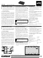
3 Branchements
1) Pour éviter tout bruit de commutation, éteignez
tout d’abord les appareils à relier aux sorties ou
coupez leurs entrées ou diminuez-les.
2) Reliez les sorties des sources audio aux prises
d’entrée LINE IN (1).
3) Reliez les entrées des appareils audio à relier
directement (p. ex. amplificateur, autres LSP-102)
aux sorties DIRECT OUT (2).
4) Reliez les entrées des appareils audio suivants à
découpler (p. ex. amplificateur, table de mixage)
aux sorties respectives ISO OUT (3).
5) Si besoin, commutez l’interrupteur Groundlift (4)
correspondant de la position GND sur la position
LIFT (masses séparées).
4 Caractéristiques techniques
Impédance source optimale : � � 50 – 600 Ω
Impédance de charge optimale : ≥ 5 kΩ
Propriétés du transformateur
Bande passante : � � � � � � � � � 20 – 20 000 Hz
Impédance : � � � � � � � � � � � � � 600 Ω à 1 kHz
Tension d’entrée màx� à 40 Hz,
taux de distorsion < 1 % : � � 5 V
Dimensions, poids :
� � � � � � � � � 160× 55 × 105 mm, 980 g
Tout droit de modification réservé.
FrançaisItaliano
Diagramme du circuit de base (1 canal) • Schema elettrico di principio (1 canale)

ELECTRONICS FOR SPECIALISTS ELECTRONICS FOR SPECIALISTS ELECTRONICS FOR SPECIALISTS ELECTRONICS FOR SPECIALISTS ELECTRONICS FOR SPECIALISTS ELECTRONICS
MONACOR INTERNATIONAL GmbH & Co. KG • Zum Falsch 36 • 28307 Bremen • Germany
Copyright
©
by MONACOR INTERNATIONAL. All rights reserved.
A-0681.99.03.07.2016
LINE IN
LINE IN
ISO OUT
1
ISO OUT
1
DIRECT OUT
DIRECT OUT
ISO OUT
2
ISO OUT
2
LSP-102
A
B
LIFT
GND
LIFT
GND
LIFT
GND
LIFT
GND
41 2
43 3
1 2
4 43 3
1
2
3
1
2
3
LINE IN ISO OUT 1
LIFT
GND
1
2
3
ISO OUT 2
1
2
3
DIRECT
OUT
LIFT
GND
LSP-102 Ref. Núm. • Num kat. 25.1680
Dwukanałowy spliter liniowy
Niniejsza instrukcja przeznaczona jest dla
użytkowników, którzy nie posiadają wiedzy i
doświadczenia technicznego. Przed rozpoczę-
ciem użytkowania proszę zapoznać się z in-
strukcją, a następnie zachować ją do wglądu.
1 Zastosowanie
LSP-102 umożliwia rozdzielenie jednego sygnału
liniowego na kilka wyjść. Dwa nie zależne tory
sygnałowe (A i B) umożliwiają np. połączenie
wyjścia stereo miksera z wejściami stereo dwóch
wzmacniaczy i jednego rejestratora. Specjalne
transformatory audio zapewniają izolację galwa-
niczną obu sygnałów wyjściowych. Dodatkowo
LSP-102 posiada wyjście przepustowe, bezpośred-
nio połączone z wejściem.
Masę sygnałową wyjść można odłączyć od
masy wejścia za pomocą włącznika Groundlift,
dzięki czemu eliminuje się pętlę masy powodującą
przydźwięki sieciowe. Pętla masy powstaje gdy
dwa urządzenia są połączone ze sobą elektrycznie
w stojaku rack przez masę sygnałową oraz przez
przewód uziemiający kabla zasilającego lub przez
obudowę.
2 Bezpieczeństwo użytkowania
Urządzenie spełnia wszystkie wymagania norm UE i
dlatego posiada oznaczenie symbolem .
•
Urządzenie przeznaczone jest do użytku je dynie
wewnątrz pomieszczeń. Należy chronić je przed
bezpośrednim kontaktem z wodą, działaniem
wilgoci oraz wysokiej temperatury (dopuszczalna
temperatura otoczenia pracy: 0 – 40 ºC).
•
Do czyszczenia urządzenia należy używać suchej,
miękkiej tkaniny. Nie wolno stosować wody ani
chemicznych środków czyszczących.
•
Producent ani dostawca nie ponoszą odpo-
wiedzialności za wynikłe szkody (uszkodzenie
sprzętu lub obrażenia użytkownika), jeśli urzą-
dzenie używano niezgodnie z przezna czeniem,
nieprawidłowo podłączono, obsłu giwano bądź
poddano nieautoryzowanej naprawie.
Po całkowitym zakończeniu eksploatacji
urządzenia należy oddać je do punktu uty-
lizacji odpadów, aby uniknąć zanieczysz-
czenia środowiska.
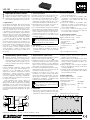
3 Połączenia
1) Aby zapobiec powstaniu trzasków podczas włą-
czania należy wyłączyć urządzenia, które będą
podłączane do wyjść, lub wyciszyć ich wejścia.
2) Należy podłączyć wyjścia źródeł sygnału do
gniazd wejściowych LINE IN (1).
3) Należy połączyć wejścia urządzeń audio, które
mają być bezpośrednio podłączone (np. wzmac-
niacza, kolejnego urządzenia LSP-102) z wyj-
ściami DIRECT OUT (2).
4) Należy podłączyć wejścia kolejnych urzą dzeń
audio (np. wzmacniacza, miksera) do odpowied-
nich wyjść ISO OUT (3).
5) W razie potrzeby można włączyć funkcję Ground-
lift zmieniając pozycję włącznika (4) z GND na
LIFT (przerwanie pętli masy).
4 Dane techniczne
Optymalna impedancja źródła: � � � � � � 50 – 600 Ω
Optymalna impedancja obciążenia: � � ≥ 5 kΩ
Charakterystyka transformatora
pasmo przenoszenia: � � � � � � � � � � � 20 – 20 000 Hz
impedancja: � � � � � � � � � � � � � � � � � � 600 Ω / 1 kHz
maks� napięcie wejściowe /40 Hz,
THD < 1 %: � � � � � � � � � � � � � � � � � � 5 V
Wymiary: � � � � � � � � � � � � � � � � � � � � � � 160 × 55 × 105 mm
Waga: � � � � � � � � � � � � � � � � � � � � � � � � 980 g
Z zastrzeżeniem możliwości zmiany.
Repartidor de línea 2 canales
Estas instrucciones van dirigidas a usuarios sin
ningún conocimiento técnico específico. Lea
atentamente estas instrucciones antes de utili-
zar el aparato y guárdelas para usos posteriores.
1 Aplicaciones
El LSP-102 ha sido diseñado para repartir una señal
de línea hacia varias salidas. Tiene dos vías de señal
independientes (A y B) de manera que p. ej. la salida
estéreo de una mesa de mezclas puede ser conec-
tada a las entradas estéreo de dos amplificadores
y un grabador. Para desacoplar las dos salidas las
señales se suministran mediante transformadores
audio especiales y por tanto están aisladas galvá-
nicamente. Además, existe una salida de alimenta-
ción que está directamente conectada a la entrada.
La masa de señal de las salidas desacopladas
puede ser separada en cada caso mediante un
interruptor desde la masa de la entrada. De este
modo, se puede interrumpir un bucle de masa que
puede causar un ruido de zumbido que interfiere.
Esto ocurre p. ej. cuando las unidades conectadas
entran en contacto en el rack mediante la masa de
señal y mediante el conductor conectado a tierra
de la alimentación o una conexión conductora de
las carcasas.
2 Notas importantes
La unidad corresponde a todas las directivas rele-
vantes de la UE y por ello está marcada con .
•
La unidad sólo está indicada para un uso en in-
terior. Protéjala contra proyecciones de agua y
salpicaduras, humedad elevada del aire, y calor
(temperatura de ambiente admisible 0 – 40 °C).
•
Para la limpieza use sólo un paño seco y suave, no
utilice nunca productos químicos o agua.
•
No se aceptará ninguna reclamación de garantía
para la unidad ni se asumirá ninguna responsabi-
lidad en caso de daño material o patrimonial cau-
sado si la unidad se usa para otros fines distintos
a aquellos para los que fue concebida, si no se
conecta correctamente, o si no se utiliza o repara
de manera experta.
Si se debe retirar la unidad del funciona-
miento definitivamente, llévela a un cen-
tro de reciclaje local para su disposición no
perjudicial para el medio ambiente.
3 Conexiones
1) Para prevenir ruido de conmutación, por el
momento apague las unidades que deban ser
conectadas a las salidas, o silencie sus entradas
o redúzcalas.
2) Conecte las salidas de las fuentes audio a los
jacks de entrada LINE IN (1).
3) Conecte las entradas de las unidades audio
que deban ser conectadas directamente (p. ej.
amplificador, otras unidades LSP-102) a las
salidas DIRECT OUT (2).
4) Conecte las entradas de las unidades audio
siguientes que deban ser desacopladas (p. ej.
amplificador, mesa de mezclas) a las correspon-
dientes salidas ISO OUT (3).
5) Si es necesario, conmute el interruptor ground-
lift correspondiente (4) de la posición GND a la
posición LIFT (masas separadas).
4 Características técnicas
Impedancia óptima de la fuente: � � 50 – 600 Ω
Impedancia óptima de la carga: � � � ≥ 5 kΩ
Características del transformador
Gama de frecuencia: � � � � � � � � � � 20 – 20 000 Hz
Impedancia: � � � � � � � � � � � � � � � � 600 Ω a 1 kHz
Voltaje de entrada máx� a 40 Hz,
tasa de distorsión < 1 %: � � � � � � 5 V
Dimensiones: � � � � � � � � � � � � � � � � � 160 × 55 × 105 mm
Peso: � � � � � � � � � � � � � � � � � � � � � � � 980 g
Sujeto a modificaciones técnicas.
EspañolPolski
Diagrama de circuito básico (1 canal) • Schemat zasadniczy (1 kanał)
-
 1
1
-
 2
2
-
 3
3


in altre lingue
Documenti correlati
-
IMG STAGELINE LSP-102 Manuale utente
-
-
-
-
-
IMG STAGELINE 24.4220 Manuale del proprietario
-
-
-
-
IMG STAGELINE DIB-100 Manuale utente