
ELECTRONICS FOR SPECIALISTS ELECTRONICS FOR SPECIALISTS ELECTRONICS FOR SPECIALISTS ELECTRONICS FOR SPECIALISTS ELECTRONICS FOR SPECIALISTS ELECTRONICS
LC-31
Bestell-Nr. • Order No. 25.1670
MONACOR INTERNATIONAL GmbH & Co. KG • Zum Falsch 36 • 28307 Bremen • Germany
Copyright
©
by MONACOR INTERNATIONAL. All rights reserved.
A-0680.99.03.08.2016
4
4
1 2 3
1 2 3
A
B
LC-31
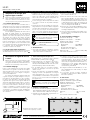
GND LIFTLINE IN 1 LINE IN 2
TRANSFORMER
LINE OUT
GND LIFTLINE IN 1 LINE IN 2
TRANSFORMER
LINE OUT
1
2
3
1
2
3
1
2
3
LINE IN 1 LINE OUT
LIFT
GND
LINE IN 2
2-Channel Line Signal Mixing
Adapter
These instructions are intended for users with-
out any specific technical knowledge. Please
read these operating instructions carefully prior
to operation and keep them for later reference.
1 Applications
The LC-31 has been designed to mix together two
line signals to one signal. It has two independent
signal ways (A and B) so that e. g. the stereo outputs
of two mixers may be connected to the stereo input
of an amplifier.
For galvanic isolation of the two signal sources,
each input signal is routed via a transformer. In addi-
tion, the signal ground of this decoupled input can
be separated by means of a switch from the ground
of the output and the ground of the other input.
Thus, a ground loop which may cause an interfering
hum noise can be interrupted. It occurs e. g. when
the two signal sources have contact in the rack both
via the signal ground and via the earthed conductor
of the power supply or a conductive connection of
the housings.
2 Important Notes
The unit corresponds to all relevant directives of the
EU and is therefore marked with .
•
The unit is suitable for indoor use only. Protect it
against dripping water and splash water, high air
humidity, and heat (admissible ambient tempera-
ture range 0 – 40 °C).
•
For cleaning only use a dry, soft cloth, by no means
chemicals or water.
•
No guarantee claims for the unit and no liability for
any resulting personal damage or material damage
will be accepted if the unit is used for other pur-
poses than originally intended, if it is not correctly
connected or operated, or if it is not repaired in an
expert way.
If the unit is to be put out of operation
definitively, take it to a local recycling plant
for a disposal which is not harmful to the
environment.
3 Connections
1) To prevent switching noise, for the time being
switch off the units to be connected to the out-
puts, or mute their inputs or reduce the volume
of their inputs.
2) Connect the outputs of the first audio source to
the input jacks LINE IN 1 (3).
3) Connect the outputs of the second audio source
to the input jacks LINE IN 2 (2). This input is gal-
vanically isolated from the first input and the
output by a transformer. In addition, the ground
connection of this input can be separated with
the groundlift switch (4) from the ground of the
connections LINE IN 1 (3) and LINE OUT (1).
4) Connect the corresponding output LINE OUT(1)
to the input of the following audio unit (e. g. am-
plifier, mixer).
5) If required, switch the corresponding ground lift
switch (4) from position GND to position LIFT
(grounds separated).
4 Specifications
Decoupling resistors: � � � � � � � � � 1 kΩ
Optimum source impedance: � � � 50 – 600 Ω
Optimum load impedance: � � � � � ≥ 5 kΩ
Characteristics of the transformer
frequency range: � � � � � � � � � � � 20 – 20 000 Hz
impedance: � � � � � � � � � � � � � � � 600 Ω at 1 kHz
max� input voltage
at 1 % THD, 40 Hz: � � � � � � � � � 5 V
Dimensions:
� � � � � � � � � � � � � � � � 160 × 55 × 85 mm
Weight: � � � � � � � � � � � � � � � � � � � 780 g
Subject to technical modification.
2-Kanal-Line-Signal-
Mischadapter
Diese Anleitung richtet sich an Benutzer ohne
besondere Fachkenntnisse. Bitte lesen Sie die
Anleitung vor dem Betrieb gründlich durch und
heben Sie sie für ein späteres Nachlesen auf.
1 Einsatzmöglichkeiten
Der LC-31 ist dafür konzipiert, zwei Line-Signale zu
einem zusammenzumischen. Er hat zwei unabhän-
gige Signalwege (A und B), sodass z. B. die Stereo-
Ausgänge zweier Mischpulte an den Stereo-Eingang
eines Verstärkers angeschlossen werden können.
Zur galvanischen Trennung der beiden Signal-
quellen wird jeweils ein Eingangssignal über einen
Übertrager geführt. Zusätzlich kann die Signalmasse
dieses entkoppelten Eingangs mithilfe eines Schalters
von der Masse des Ausgangs und der Masse des an-
deren Eingangs getrennt werden. So lässt sich eine
Masseschleife, die ein störendes Brummen verur-
sachen kann, auftrennen. Sie entsteht z. B. wenn
beide Signalquellen sowohl über die Signalmasse
als auch über den Schutzleiter der Stromversorgung
oder über eine leitende Verbindung der Gehäuse im
Rack Kontakt haben.
2 Wichtige Hinweise für den Gebrauch
Das Gerät entspricht allen relevanten Richtlinien der
EU und ist deshalb mit
gekennzeichnet.
•
Verwenden Sie das Gerät nur im Innenbereich.
Schützen Sie es vor Tropf- und Spritzwasser, hoher
Luftfeuchtigkeit und Hitze (zulässiger Einsatztem-
peraturbereich 0 – 40 °C).
•
Verwenden Sie für die Reinigung nur ein trockenes,
weiches Tuch, niemals Chemikalien oder Wasser.
•
Wird das Gerät zweckentfremdet, nicht richtig an-
geschlossen, falsch bedient oder nicht fachgerecht
repariert, kann keine Haftung für daraus resultie-
rende Sach- oder Personenschäden und keine Ga-
rantie für das Gerät übernommen werden.
Soll das Gerät endgültig aus dem Betrieb
genommen werden, übergeben Sie es zur
umweltgerechten Entsorgung einem ört-
lichen Recyclingbetrieb.
3 Anschlüsse herstellen
1) Zur Vermeidung von Schaltgeräuschen die an die
Ausgänge anzuschließenden Geräte zunächst
ausschalten oder deren Eingänge stummschalten
oder herunterregeln.
2) Die Ausgänge der ersten Audioquelle an die Ein-
gangsbuchsen LINE IN 1 (3) anschließen.
3) Die Ausgänge der zweiten Audioquelle an die
Eingangsbuchsen LINE IN 2 (2) anschließen. Die-
ser Eingang ist durch einen Übertrager von dem
ersten Eingang und dem Ausgang galvanisch ge-
trennt. Die Masseverbindung dieses Anschlusses
kann zudem mit dem Groundlift-Schalter (4) von
der Masse der Anschlüsse LINE IN 1 (3) und LINE
OUT(1) getrennt werden.
4) Den jeweiligen Ausgang LINE OUT (1) mit dem
Eingang des nachfolgenden Audiogerätes (z. B.
Verstärker, Mischpult) verbinden.
5) Wenn nötig, den jeweiligen Groundlift-Schalter
(4) von der Position GND auf die Position LIFT
(Massen getrennt) umschalten.
4 Technische Daten
Entkopplungswiderstände: � � � � � 1 kΩ
Optimale Quellimpedanz: � � � � � � 50 – 600 Ω
Optimale Lastimpedanz: � � � � � � � ≥ 5 kΩ
Eigenschaften des Übertragers
Frequenzbereich: � � � � � � � � � � � 20 – 20 000 Hz
Impedanz: � � � � � � � � � � � � � � � 600 Ω bei 1 kHz
Max� Eingangsspannung
bei 1 % Klirrfaktor, 40 Hz: � � � � 5 V
Abmessungen:
� � � � � � � � � � � � � � 160 × 55 × 85 mm
Gewicht: � � � � � � � � � � � � � � � � � � 780 g
Änderungen vorbehalten.
DeutschEnglish
Prinzipschaltbild (1 Kanal)
Basic circuit diagram (1 channel)

ELECTRONICS FOR SPECIALISTS ELECTRONICS FOR SPECIALISTS ELECTRONICS FOR SPECIALISTS ELECTRONICS FOR SPECIALISTS ELECTRONICS FOR SPECIALISTS ELECTRONICS
MONACOR INTERNATIONAL GmbH & Co. KG • Zum Falsch 36 • 28307 Bremen • Germany
Copyright
©
by MONACOR INTERNATIONAL. All rights reserved.
A-0680.99.03.08.2016
4
4
1 2 3
1 2 3
A
B
LC-31
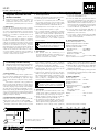
GND LIFTLINE IN 1 LINE IN 2
TRANSFORMER
LINE OUT
GND LIFTLINE IN 1 LINE IN 2
TRANSFORMER
LINE OUT
1
2
3
1
2
3
1
2
3
LINE IN 1 LINE OUT
LIFT
GND
LINE IN 2
LC-31
Référence num. • Codice 25.1670
Miscelatore di segnali di linea a
2 canali
Queste istruzioni sono rivolte all‘utente senza
conoscenze tecniche specifiche. Vi preghiamo
di leggerle attentamente prima della messa in
funzione e di conservarle per un uso futuro.
1 Possibilità d’impiego
L’LC-31 è stato realizzato per miscelare due segnali
di linea in un solo segnale. Possiede due vie indipen-
denti di segnali (A e B), in modo che le uscite stereo
di due mixer possono essere collegate con l’ingresso
stereo di un amplificatore.
Per ottenere la separazione galvanica delle due
sorgenti di segnali, un segnale d’ingresso viene por-
tato attraverso un trasformatore. In più è possibile,
per mezzo di un interruttore, separa re la massa del
segnale di detto ingresso disaccoppiato dalla massa
dell’uscita e dalla massa dell’altro ingresso. In questo
modo è possibile aprire un anello di terra che può
provocare un ronzio fastidioso. Tale anello si crea per
esempio se entrambe le sorgenti di segnali sono in
contatto nel rack sia attraverso la massa dei segnali
che attraverso il conduttore di terra dell’alimenta-
zione oppure attraverso un collegamento conduttivo
dei contenitori.
2 Avvertenze importanti per l’uso
Quest’apparecchio è conforme a tutte le direttive
rilevanti dell’UE e pertanto porta la sigla .
•
Usare l’apparecchio solo all’interno di locali. Pro-
teggerlo dall’acqua gocciolante e dagli spruzzi
d’acqua, da alta umidità dell’aria e dal calore (tem-
peratura d’impiego ammessa fra 0 e 40 °C).
•
Per la pulizia usare solo un panno morbido,
asciutto; non impiegare in nessun caso prodotti
chimici o acqua.
•
Nel caso d’uso improprio, di collegamenti sbagliati,
d’impiego scorretto o di riparazione non a regola
d’arte dell’apparecchio, non si assume nessuna
responsabilità per eventuali danni consequenziali a
persone o a cose e non si assume nessuna garanzia
per l’apparecchio.
Se si desidera eliminare l’apparecchio defini-
tivamente, consegnarlo per lo smaltimento
ad un’istituzione locale per il riciclaggio.
3 Eseguire i collegamenti
1) Per escludere rumori di collegamento conviene spe-
gnere dapprima gli apparecchi da collegare con le
uscite o mettere su muto o abbassare i loro ingressi.
2) Collegare le uscite della prima sorgente audio con
le prese d’ingresso LINE IN 1 (3).
3) Collegare le uscite della seconda sorgente audio
con le prese d’ingresso LINE IN 2 (2). Per mezzo
di un trasformatore, questo ingresso dispone di
separazione galvanica dal primo ingresso e dall’u-
scita. Inoltre, il collegamento di massa di detto col-
legamento può essere separato dalla massa dei
contatti LINE IN 1 (3) e LINE OUT (1) con l’aiuto di
un interruttore groundlift (4).
4) Collegare la relativa uscita LINE OUT (1) con l’in-
gresso dell’apparecchio audio a valle (p. es. ampli-
ficatore, mixer).
5) Se necessario, spostare il relativo interruttore
groundlift (4) dalla posizione GND in posizione
LIFT (masse separate).
4 Dati tecnici
Resistenze di disaccoppiamento: � 1 kΩ
Impedenza ottimale della sorgente: 50 – 600 Ω
Impedenza ottimale del carico: � � � ≥ 5 kΩ
Caratteristiche del trasformatore
Gamma di frequenze: � � � � � � � � 20 – 20 000 Hz
Impedenza: � � � � � � � � � � � � � � � � 600 Ω con 1 kHz
Tensione max� d’ingresso con
fattore di distorsione 1 %, 40 Hz: 5 V
Dimensioni:
� � � � � � � � � � � � � � � � � 160 × 55 × 85 mm
Peso: � � � � � � � � � � � � � � � � � � � � � � 780 g
Con riserva di modifiche tecniche.
Adaptateur de mixage pour
signaux ligne 2 canaux
Cette notice s‘adresse aux utilisateurs sans connais-
sances techniques particulières. Veuillez lire la pré-
sente notice avant le fonctionnement et conser-
vez-la pour pouvoir vous y reporter ultérieurement.
1 Possibilités d’utilisation
Le LC-31 est conçu pour mixer ensemble deux si-
gnaux ligne en un seul. Il a deux voies indépendantes
(A et B) de sorte que par exemple les sorties stéréo de
deux tables de mixage puissent être reliées à l’entrée
stéréo d’un amplificateur.
Pour la séparation galvanique des deux sources
de signal, un signal d’entrée est respectivement
dirigé via un transformateur. En plus, la masse du
signal de cette entrée découplée peut être séparée
de la masse de la sortie et de la masse de l’autre
entrée grâce à un interrupteur. Ainsi, un bouclage de
masse pouvant causer un ronflement perturbateur
peut être interrompu. Il se crée par exemple lorsque
deux sources de signaux ont un contact dans le rack
non seulement via la masse de signal mais aussi via
le conducteur terre de l’alimentation ou via une
connexion conductrice des boîtiers.
2 Conseils importants d’utilisation
Cet appareil répond à toutes les directives nécessaires
de l’Union Européenne et porte donc le symbole .
•
L’appareil n’est conçu que pour une utilisation en
intérieur. Protégez-le de tout type de projections
d’eau, des éclabossures, d’une humidité élevée
d’air et de la chaleur (plage de température de
fonctionnement autorisée : 0 – 40 °C).
•
Pour le nettoyage, utilisez uniquement un chiffon
sec et doux, en aucun cas de produits chimiques
ou d’eau.
•
Nous déclinons toute responsabilité en cas de dom-
mages matériels ou corporels résultants si l’appareil
est utilisé dans un but autre que celui pour lequel
il a été conçu, s’il n’est pas correctement branché,
utilisé ou n’est pas réparé par une personne ha-
bilitée, en outre, la garantie deviendrait caduque.
Lorsque l’appareil est définitivement retiré
du service, vous devez le déposer dans une
usine de recyclage adaptée pour contribuer
à son élimination non polluante.
CARTONS ET EMBALLAGE
PAPIER À TRIER
3 Branchements
1) Pour éviter tout bruit de commutation, étei gnez
tout d’abord les appareils à relier aux sorties ou
coupez leurs entrées ou diminuez-les.
2) Reliez les sorties de la première source audio aux
prises d’entrée LINE IN 1 (3).
3) Reliez les sorties de la seconde source audio aux
prises d’entrée LINE IN 2 (2). Cette en trée est sé-
parée galvaniquement de la première entrée et de
la sortie par un transformateur. La liaison masse de
ce branchement peut, en plus, être séparée de la
masse des branchements LINE IN 1 (3) et LINE OUT
(1) avec l’interrupteur Groundlift (4).
4) Reliez la sortie correspondante LINE OUT (1) à l’en-
trée de l’appareil audio suivant (par exemple table
de mixage, amplificateur).
5) Si besoin, mettez l’interrupteur Groundlift corres-
pondant (4) de la position GND sur la position LIFT
(masses séparées).
4 Caractéristiques techniques
Résistances de découplage : � � � � 1 kΩ
Impédance source optimale : � � � 50 – 600 Ω
Impédance charge optimale : � � � ≥ 5 kΩ
Propriétés du transformateur
Bande passante : � � � � � � � � � � 20 – 20 000 Hz
Impédance : � � � � � � � � � � � � � � 600 Ω à 1 kHz
Tension d’entrée maximale pour
taux de distorsion 1 %, 40 Hz : 5 V
Dimensions, poids :
� � � � � � � � � � 160 × 55 × 85 mm, 780 g
Tout droit de modification réservé.
FrançaisItaliano
Diagramme du circuit de base (1 canal)
Schema elettrico di principio (1 canale)

ELECTRONICS FOR SPECIALISTS ELECTRONICS FOR SPECIALISTS ELECTRONICS FOR SPECIALISTS ELECTRONICS FOR SPECIALISTS ELECTRONICS FOR SPECIALISTS ELECTRONICS
MONACOR INTERNATIONAL GmbH & Co. KG • Zum Falsch 36 • 28307 Bremen • Germany
Copyright
©
by MONACOR INTERNATIONAL. All rights reserved.
A-0680.99.03.08.2016
4
4
1 2 3
1 2 3
A
B
LC-31
GND LIFTLINE IN 1 LINE IN 2
TRANSFORMER
LINE OUT
GND LIFTLINE IN 1 LINE IN 2
TRANSFORMER
LINE OUT
1
2
3
1
2
3
1
2
3
LINE IN 1 LINE OUT
LIFT
GND
LINE IN 2
LC-31
Ref. Núm. • Numer kat. 25.1670
2-kanałowy sumator liniowy
Niniejsza instrukcja przeznaczona jest dla użyt-
kowników, którzy nie posiadają wiedzy i do-
świadczenia technicznego. Przed rozpoczęciem
użytkowania proszę zapoznać się z instrukcją, a
następnie zachować ją do wglądu.
1 Zastosowanie
LC-31 służy do sumowania dwóch sygnałów linio-
wych do jednego sygnału. Dwa niezależne tory sy-
gnałowe (A i B) umożliwiają np. połączenie wyjść
stereo dwóch mikserów z wejściem stereo wzmac-
niacza.
Transformator zapewnia izolację galwaniczną
dwóch źródeł sygnału. Dodatkowo można odłączyć
masę sygnałową jednego wejścia od masy wyjścia
oraz masy drugiego wejścia. Dzięki temu eliminuje
się pętlę masy powodującą przydźwięki sieciowe.
Pętla masy powstaje gdy dwa źródła sygnału są połą-
czone ze sobą elektrycznie w stojaku rack przez masę
sygnałową oraz przez przewód uziemiający kabla za-
silającego lub przez obudowę.
2 Bezpieczeństwo użytkowania
Urządzenie spełnia wszystkie wymagania norm UE,
dzięki czemu zostało oznaczone symbolem .
•
Urządzenie przeznaczone jest do użytku jedynie
wewnątrz pomieszczeń. Należy chronić je przed
bezpośrednim kontaktem z wodą, działaniem
wilgoci oraz wysokiej temperatury (dopuszczalna
temperatura otoczenia pracy: 0 – 40 °C).
•
Do czyszczenia urządzenia należy używać suchej,
miękkiej tkaniny. Nie wolno stosować wody ani
chemicznych środków czyszczących.
•
Producent ani dostawca nie ponoszą odpowie-
dzialności za wynikłe szkody (uszkodzenie sprzętu
lub obrażenia użytkownika), jeśli urządzenie uży-
wano niezgodnie z przeznaczeniem, nieprawi-
dłowo podłączono, obsługiwano bądź poddano
nieautoryzowanej naprawie.
Po całkowitym zakończeniu eksploatacji
urządzenia, należy oddać je do punktu re-
cyklingu, aby nie zaśmiecać środowiska.
3 Połączenia
1) Aby zapobiec powstaniu trzasków podczas włą-
czania należy wyłączyć urządzenia, które będą
podłączane do wyjść, lub wyciszyć ich wejścia.
2) Należy podłączyć wyjścia pierwszego źródła sy-
gnału do gniazd wejściowych LINE IN 1 (3).
3) Do gniazd wejściowych LINE IN 2 (2) należy pod-
łączyć wyjście drugiego źródła sygnału. Transfor-
mator zapewnia izolację galwaniczną obu wejść.
Dodatkowo można odłączyć masę sygnałową
jednego wejścia od masy złącza LINE IN 1 (3) oraz
LINE OUT (1) za pomocą włącznika Groundlift (4).
4) Należy podłączyć odpowiednie wyjście LINE OUT
(1) do wejścia kolejnego urządzenia audio (np.
wzmacniacza, miksera).
5) W razie potrzeby można włączyć funkcję Ground-
lift zmieniając pozycję włącznika (4) z GND na LIFT
(przerwanie pętli masy).
4 Dane techniczne
Rezystory separujące: � � � � � � � � � 1 kΩ
Optymalna impedancja źródła: � � 50 – 600 Ω
Optymalna impedancja
obciążenia:
� � � � � � � � � � � � � � � � ≥ 5 kΩ
Charakterystyka transformatora
pasmo przenoszenia: � � � � � � � � 20 – 20 000 Hz
impedancja: � � � � � � � � � � � � � � 600 Ω / 1 kHz
maks� napięcie wejściowe
1 % THD, 40 Hz: � � � � � � � � � � � 5 V
Wymiary:
� � � � � � � � � � � � � � � � � � 160 × 55 × 85 mm
Waga: � � � � � � � � � � � � � � � � � � � � 780 g
Z zastrzeżeniem możliwości zmiany.
Adaptador mezclador de señal
de línea 2 canales
Estas instrucciones van dirigidas a usuarios sin
ningún conocimiento técnico específico. Lea
atentamente estas instrucciones antes de utili-
zar el aparato y guárdelas para usos posteriores.
1 Aplicaciones
El LC-31 ha sido diseñado para mezclar conjunta-
mente dos señales de línea en una sola señal. Tiene
dos vías de señal independientes (A y B) de manera
que p. ej. las salidas estéreo de dos mesas de mezclas
pueden ser conectadas a la entrada estéreo de un
amplificador.
Para el aislamiento galvánico de las dos fuen-
tes de señal, cada señal de entrada se suministra
mediante un transformador. Además, la masa de
señal de esta entrada desacoplada se puede separar
mediante un interruptor de la masa de la salida y la
masa de la otra entrada. De este modo, se puede
interrumpir un bucle de masa que puede causar un
ruido de zumbido que interfiere. Esto ocurre p. ej.
cuando las dos fuentes de señal entran en contacto
en el rack mediante la masa de señal y mediante el
conductor unido a tierra de la alimentación o una
conexión conductora de las carcasas.
2 Notas importantes
El aparato corresponde a todas las directivas relevan-
tes por la UE y por ello está marcado con .
•
El aparato sólo está indicado para un uso en inte-
rior. Protéjalo contra proyecciones de agua y salpi-
caduras, humedad elevada del aire, y calor (gama
de temperatura ambiente admisible 0 – 40 °C.
•
Para la limpieza use sólo un paño seco y suave, no
utilice nunca productos químicos o agua.
•
No se aceptará ninguna reclamación de garantía
para el aparato ni se asumirá ninguna responsabi-
lidad en caso de daño material o patrimonial cau-
sado si el aparato se usa para otros fines distintos
a aquellos para los que fue diseñado, si no se co-
necta correctamente, o si no se utiliza o repara de
manera experta.
Si va a poner el aparato fuera de servicio de-
finitivamente, llévelo a la planta de reciclaje
de la zona para que su eliminación no sea
perjudicial para el medio ambiente.
3 Conexiones
1) Para prevenir ruido de conmutación, por el
momento apague los aparatos que deban ser co-
nectados a las salidas, o silencie sus en tradas o
reduzca el volumen de sus entradas.
2) Conecte las salidas de la primera fuente audio a
los jacks de entrada LINE IN 1 (3).
3) Conecte las salidas de la segunda fuente audio a
los jacks de entrada LINE IN 2 (2). Esta entrada se
aísla galvánicamente de la primera entrada y la
salida mediante un transformador. Además, la co-
nexión de masa de esta entrada se puede separar
con el interruptor groundlift (4) de la masa de las
conexiones LINE IN 1 (3) y LINE OUT (1).
4) Conecte la salida correspondiente LINE OUT (1)
a la entrada de la unidad audio siguiente (p. ej.
amplificador, mesa de mezclas).
5) Si es necesario, conmute el interruptor groundlift
correspondiente (4) de la posición GND a la posi-
ción LIFT (masas separadas).
4 Características técnicas
Resistores de desacoplamiento: � 1 kΩ
Impedancia óptima de la fuente: 50 – 600 Ω
Impedancia óptima de la carga: � ≥ 5 kΩ
Características del transformador
Gama de frecuencia: � � � � � � � � 20 – 20 000 Hz
Impedancia: � � � � � � � � � � � � � � 600 Ω a 1 kHz
Voltaje de entrada máx� a tasa
de distorsión 1 %, 40 Hz: � � � � � 5 V
Dimensiones, peso:
� � � � � � � � � � 160 × 55 × 85 mm, 780 g
Sujeto a modificaciones técnicas.
EspañolPolski
Diagrama de circuito básico (1 canal)
Schemat zasadniczy (1 kanał)
-
 1
1
-
 2
2
-
 3
3


in altre lingue
- français: IMG STAGELINE LC-31 Manuel utilisateur
- español: IMG STAGELINE LC-31 Manual de usuario
- Deutsch: IMG STAGELINE LC-31 Benutzerhandbuch
- polski: IMG STAGELINE LC-31 Instrukcja obsługi
Documenti correlati
-
IMG STAGELINE FGA-202 Manuale utente
-
-
-
-
IMG STAGELINE 24.4220 Manuale del proprietario
-
-
-
IMG STAGELINE DIB-100 Manuale utente
-
IMG STAGELINE MPX-20USB Manuale utente
-