CHAUVIN ARNOUX CAPAC10 Manuale utente
- Categoria
- Misurazione, test
- Tipo
- Manuale utente
Questo manuale è adatto anche per

1
■■
■■
■PINCE AMPEREMETRIQUE
■■
■■
■AC - DC CURRENT CLAMP
■■
■■
■ZANGENSTROMWANDLER
■■
■■
■PINZA AMPEROMETRICA
■■
■■
■PINZA AMPERIMETRICA
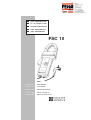
PAC 10
Mode d'Emploi
User's Manual
Bedienungsanleitung
Libretto d'Istruzioni
Manual de Instrucciones
FRANCAIS
ENGLISH
DEUTSCH
ITALIANO
ESPANOL

2
Vous venez d’acquérir une pince ampèremétrique et nous vous
remercions de votre confiance.
Pour obtenir le meilleur service de votre appareil :
■lisez attentivement ce mode d’emploi
■respectez les précautions d’emploi
Attention, risque de DANGER ! L'opérateur doit consulter la
présente notice à chaque fois que ce symbole de danger est
rencontré.
Application ou retrait autorisés sur les conducteurs non isolés
ou nus sous tension dangereuse.
Appareil entièrement protégé par isolation double ou isolation
renforcée.
Le marquage CE indique la conformité aux directives
européennes, notamment DBT et CEM.
La poubelle barrée signifie que, dans l'Union Européenne, le
produit fait l'objet d'une collecte sélective conformément à la
directive DEEE 2002/96/EC : ce matériel ne doit pas être traité
comme un déchet ménager.
PRÉCAUTIONS D’EMPLOI
■N’utiliser la pince PAC 10 qu’en intérieur.
■Ne pas exposer la pince à des chutes d’eau.
■Ne pas utiliser la pince PAC 10 sur des conducteurs non isolés portés
à un potentiel supérieur à 600 V par rapport à la terre .
■Pour les mesures en courant continu, s’assurer du zéro de la sortie
et le régler si nécessaire (voir «procédure d’emploi»).
■Lors de la mesure, s’assurer que le conducteur est bien dans
l’alignement des repères de mâchoires et que la fermeture de la pince
est correcte.
■Votre pince est livrée avec un jeu d'étiquettes adhésives. Choisissez
l'étiquette de langue adequate et collez-la au dos du boîtier.
GARANTIE
Notre garantie s’exerce, sauf stipulation expresse, pendant douze
mois après la date de mise à disposition du matériel (extrait de nos
Conditions Générales de Vente, communiquées sur demande).
POUR COMMANDER
Réf.
Pince PAC 10 ........................................................................................ P01120070
Livrée avec une pile saline 9 V, un jeu d’étiquettes cinq langues à coller
sur l’appareil et un mode d’emploi.

3
English ............................................................................................................ 8
Deutsch .......................................................................................................... 14
Italiano ............................................................................................................ 20
Español .......................................................................................................... 26
SOMMAIRE
page
1Présentation ..................................................................................................... 3
2Description ........................................................................................................ 3
3Procédure d’emploi ...................................................................................... 4
3.1 Mise en marche ......................................................................... 4
3.2 Réglage du zéro DC ................................................................ 4
3.3 Mesure ........................................................................................... 4
4Caractéristiques ............................................................................................. 4
4.1 Conditions de référence ........................................................ 4
4.2 Conditions d’utilisation ........................................................... 5
4.3 Caractéristiques métrologiques ......................................... 5
4.4 Caractéristiques mécaniques ............................................. 6
4.5 Caractéristiques électriques ................................................ 6
- Limite de fonctionnement ................................................... 6
- Chocs électriques .................................................................. 6
4.6 Compatibilité électromagnétique ....................................... 6
5Maintenance ..................................................................................................... 7
5.1 Remplacement de la pile ...................................................... 7
5.2 Nettoyage ..................................................................................... 7
5.3 Vérification métrologique ...................................................... 7
5.4 Réparation ................................................................................... 7
7Annexe ................................................................................................................. 31
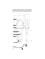
2/ DESCRIPTION
Voir schéma descriptif en fin de mode d’emploi.
➀Emplacement du conducteur pendant la mesure
➁Mâchoires
➂Garde antiglissement de protection
➃Témoin vert d’alimentation correcte
➄Commutateur marche/arrêt à glissière
➅Parties préhensibles
➆Cordon solidaire 1,5 m
➇Molette de réglage de zéro DC
➈Fiches de sécurité ∅ 4 mm
1/ PRESENTATION
La pince ampèremétrique PAC 10 mesure des courants continus et
alternatifs, sans ouvrir le circuit sur lequel ils circulent. Elle s’utilise en
accessoire de multimètre, enregistreur, etc.
Cette pince mesure les courants continus jusqu’à 600 A et les courants
alternatifs jusqu’à 400 A efficace (600 crête). Elle restitue la forme et
l’amplitude du courant mesuré sous l’aspect d’une tension qui est l'image
du courant primaire.
La PAC 10 dispose d'un calibre unique 400 A (sensibilité 1 mV/A), d’une
mollette de réglage du zéro DC et d'un témoin d'alimentation correcte.

4
3/ PROCEDURE D’EMPLOI
3.1/ MISE EN MARCHE
Mettre le commutateur à glissière ➄ sur la position calibre 400 A (sensibilité
1 mV/A). Le fonctionnement correct est signalé par le voyant de couleur
verte ➃ indiquant le bon état de la pile (alimentation correcte).
Si ce témoin vert ne s’allume pas à la mise en marche, ou vient à s’éteindre
en cours d'utilisation, il est alors nécessaire de procéder au remplacement
de la pile (voir chapitre MAINTENANCE).
3.2/ REGLAGE DU ZERO
Assurez-vous que les mâchoires ➁ de la pince sont bien fermées et
qu’elles n’enserrent aucun conducteur. Reliez la pince à votre appareil de
mesure configuré suivant le calibre tension adequat. Puis, manipulez la
molette ➇ jusqu'à obtenir zéro DC sur votre appareil de mesure.
3.3/ MESURE
Après avoir mis en marche la pince, l’avoir reliée à l’appareil de mesure
avec le calibre adequat et avoir réglé le zéro DC (voir les deux paragra-
phes précédents), enserrez le conducteur à mesurer entre les mâchoires
de la pince ➀ et la refermer.
La valeur mesurée s’affiche sur l’appareil associé.
En fonction de la sensibilité de la pince et du calibre de votre appareil de
mesure, effectuez le rapport de conversion pour obtenir la valeur du
courant.
En mesure de courant continu, s’assurer que la flèche figurant sur
le bord extérieur des mâchoires ➁ correspond au sens du courant
circulant dans le conducteur (source ⇒ récepteur).
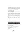
4/ CARACTERISTIQUES
Calibres rapport étendue de mesure
entrée/sortie AC eff. crête maxi DC
400 A 1 mV/A 0,5...400 A 0,5...600 A 0,5...600 A
4.1/ CONDITIONS DE RÉFERENCE
-Température : 18...28°C
-Taux d’humidité : 20...75% HR
-Tension de pile : 9 V ± 0,1 V
-Position du conducteur : centré sur les repères de la pince
-Champ magnétique : champ terrestre continu
-Absence de champ magnétique alternatif externe
-Absence de champ électrique
-
Mesure pour un courant continu ou un courant alternatif sinusoïdal ≤ 65
Hz
-Impédance de l’appareil de mesure : ≥ 1 MΩ et ≤ 100 pF

5
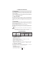
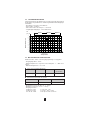
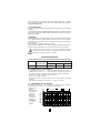
4.2/ CONDITIONS D’UTILISATION
L’appareil doit être utilisé dans les conditions suivantes pour satisfaire à
la sécurité de l’utilisateur et aux performances métrologiques :
-Utilisation en intérieur
-Altitude de fonctionnement : ≤ 2000 m
-Altitude de transport : ≤ 12 000 m
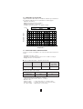
-Conditions d'environnement : voir graphe ci-après
0
10
20
30
40
50
60
70
80
90
-50 -40 -30 -20 -10 0 10 20 30 40 50 60 70 80 90
Stockage Utilisation Réference
Température
Humidité relative
▼
°C
▼
% HR Stoc-
kage
Utilisation Référence
4.3/ CARACTERISTIQUES METROLOGIQUES
Toutes les erreurs sont indiquées en % de Vs (valeur de la tension de
sortie).
-Impédance de sortie : 100 Ω
-Impédance de l'appareil de mesure associé ≥ 1 MΩ et ≤ 100 pF
-Réglage du zéro : ± 10 A environ
■Erreur intrinsèque dans le domaine de référence
Courant primaire 0,5...100 A 100...400 A 400...600 A
(en continu
uniquement)
Précision ≤ 1,5% + 1 mV ≤ 2% ≤ 2,5%
■Erreur de phase (45...65 Hz)
Courant primaire 10...100 A 100...400 A
Déphasage ≤ 2,5° ≤ 2°
- Temps de montée de 10 à 90% Vs : ≤ 100 µs
- Temps de descente de 90 à 10% Vs : ≤ 100 µs
- Bruit en sortie :
de DC à 1 kHz ≤ 1 mV crête-crête (ou 1 A crête-crête)
de DC à 5 kHz ≤ 1,5 mV crête-crête (ou 1,5 A crête-crête)
de 1 Hz à 5 kHz ≤ 500 µV rms (ou 0,5 A rms)

6
Paramètres d’influences
■Influence maxi de la fréquence sur la mesure (à ajouter à l’erreur dans
le domaine de référence) : de 65 à 440 Hz - 2%
de 440 à 1000 Hz - 5%
à 1kHz à 5 kHz - 3 dB
■Tension pile : ≤ 0,5 A/V
■Température : ≤ 300 ppm /°C ou 0,3% /10°C
■Humidité 10...85% HR à température ambiante : ≤ 0,5%
■Position d’un conducteur de ∅ 20 mm : de DC à 440 Hz < 1%
de DC Hz à 1 kHz < 1,5%
de DC à 2 kHz < 3%
de DC à 5 kHz < 10%
■Conducteur adjacent parcouru par un courant alternatif 50 ... 60 Hz,
à 23 mm de la pince : < 10 mA/A
■Influence d’un champ extérieur de 400 A/m (50 Hz) sur câble
centré : < 1,3 A
■Réjection de mode commun : > 65 dB A/V de 50 à 400 Hz
■Rémanence : < 10 mA/A pour un courant DC passant de + 600 A
à - 600 A DC
4.4/ CARACTERISTIQUES MECANIQUES
- Etanchéité : IP 30 suivant IEC 529
- Enserrage : un câble ∅ 30 mm (ou deux câbles ∅ 24 mm)
une barre de section 50 x 10 mm
- Dimensions pince hors tout : 224 x 97 x 44 mm
- Cordon solidaire : 1,5 m
- Masse : 440 g environ
- Hauteur de chute : suivant IEC 68-2-32
- Protection contre les chocs : 100 g suivant IEC 68-2-27
- Vibrations : suivant IEC 68-2-6
- Protection contre les impacts : IK04 0.5 J suivant EN 50102
4.5/ CARACTERISTIQUES ELECTRIQUES
Alimentation : pile 9 V (type 6LR61, 6LF22 ou NEDA 1604)
Autonomie : environ 120 h avec une pile alcaline
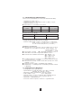
Limite de fonctionnement
En courant continu : 3000 A permanent
En alternatif : 1000 A permanent jusqu’à 1 kHz
Le courant (AC) maximal admissible en surcharge à partir de 1 kHz est
défini selon la formule suivante :
Ip max =
Chocs électriques
Appareil à double isolation ou isolation renforcée suivant IEC 61010-2-032.
Entre le primaire, le secondaire et la partie préhensible située sous la
garde, tension d’épreuve diélectrique : 7850 V DC
Tension maximum de mode commun entre le conducteur sur lequel on
fait la mesure et la terre, ou la sortie et la terre : 600 V pour les installations
de catégorie III et degré de pollution 2
Catégorie d’installation et degré de pollution suivant IEC 664 et 664 A
4.6/ COMPATIBILITÉ ÉLECTROMAGNÉTIQUE
Émission et immunité en milieu industriel selon IEC 61326-1.
1000
F(kHz)

7
5/ MAINTENANCE
Pour la maintenance, utilisez seulement les pièces de re-
change qui ont été spécifiées. Le fabricant ne pourra être
tenu pour responsable de tout accident survenu suite à
une réparation effectuée en dehors de son service après-
vente ou des réparateurs agréés.
5.1/ REMPLACEMENT DE LA PILE
-Déconnecter entièrement la pince du circuit à mesurer et de l’appareil
de mesure sur lequel elle est reliée.
-Dévisser la vis imperdable maintenant le couvercle de la trappe à pile.
-Remplacer la pile 9 V (type 6LF22, 6LR61 ou NEDA 1604).
-Revisser le couvercle de la trappe à pile.
5.2/ NETTOYAGE
Maintenir un parfait état de propreté au niveau de la fermeture des
mâchoires.
Le nettoyage du corps de la pince est à effectuer à l’aide d’un chiffon
humide imbibé d’eau savonneuse.
Le rinçage s’effectue également avec un chiffon humide imbibé d’eau
claire.
Ne jamais faire couler d’eau sur la pince.
5.3/ VERIFICATION METROLOGIQUE
Comme tous les appareils de mesure ou d'essais, une
vérification périodique est nécessaire.
Nous vous conseillons une vérification annuelle de cet appareil. Pour les
vérifications et étalonnages, adressez-vous à nos laboratoires de
métrologie accrédités COFRAC ou aux centres techniques
MANUMESURE.
Renseignements et coordonnées sur demande :
Tél. : 02 31 64 51 55 - Fax : 02 31 64 51 72
5.4/ RÉPARATION
Pour les réparations sous garantie et hors garantie, contactez votre
agence commerciale Chauvin Arnoux la plus proche ou votre centre
technique régional Manumesure qui établira un dossier de retour et vous
communiquera la procédure à suivre.
Coordonnées disponibles sur notre site : http://www.chauvin-arnoux.com
ou par téléphone aux numéros suivants : 02 31 64 51 55 (centre technique
Manumesure) , 01 44 85 44 85 (Chauvin Arnoux).
Pour les réparations hors de France métropolitaine, sous garantie et
hors garantie, retournez l'appareil à votre agence Chauvin Arnoux locale
ou à votre distributeur.

8
English
Thank you for purchasing a Chauvin Arnoux AC/DC current clamp.
To get the best service from this instrument:
■read this user’s manual carefully
■respect the safety precautions detailed
SAFETY PRECAUTIONS
■Only use the PAC 10 clamp indoors.
■Do not expose the clamp to running water.
■Do not use the PAC 10 clamp on uninsulated conductors at a voltage
of more than 600 V in relation to the earth.
■For measurements on DC current, check zero output and adjust if
necessary (see “ Operating procedure ”).
■During measurement, ensure that the conductor is in line with the
markings on the jaws and that the clamp closes correctly.
■Your clamp is supplied with a set of adhesive labels. Choose the
language and stick it to the back of the case.
WARRANTY
Our guarantee is applicable for twelve months after the date on
which the equipment is made available (extract from our General
Conditions of Sale, available on request).
TO ORDER
Ref.
Clamp PAC 10 ..................................................................................... P01120070
Supplied with a 9 V battery, a set of labels in 5 languages to stick to the
instrument, and a User Manual.
WARNING, risk of DANGER ! The operator must refer to these
instructions whenever this danger symbol appears.
Application or withdrawal authorized on conductors containing
dangerous voltages. Type A current sensor as per IEC 61010-2-032.
Equipment protected throughout by double or reinforced
insulation.
The CE marking indicates conformity with European directives,
in particular LVD and EMC.
The rubbish bin with a line through it indicates that, in the
European Union, the product must undergo selective disposal
in compliance with Directive WEEE 2002/96/EC. This equipment
must not be treated as household waste.

9
SUMMARY
Page
1Presentation ...................................................................................................... 9
2Description ........................................................................................................ 9
3Operating procedure ................................................................................... 10
3.1 Switching on ................................................................................ 10
3.2 DC zero adjustment ................................................................. 10
3.3 Measurement .............................................................................. 10
4Specifications .................................................................................................. 10
4.1 Reference conditions ............................................................... 10
4.2 Operating conditions ................................................................ 10
4.3 Metrological specifications .................................................... 11
4.4 Mechanical specifications ..................................................... 12
4.5 Electrical specifications ......................................................... 12
- Operating limits ....................................................................... 12
- Electric shocks ........................................................................ 12
4.6 Electromagnetic compatibility ............................................. 12
5Maintenance ...................................................................................................... 13
5.1 Replacing the battery .............................................................. 13
5.2 Cleaning ........................................................................................ 13
5.3 Calibration .................................................................................... 13
5.4 Repair ............................................................................................. 13
6Appendix ............................................................................................................. 31
1/ PRESENTATION
The PAC 10 current clamp measures DC or AC currents, without opening
the circuit they are flowing in. The current clamp is used as an accessory
for multimeters, recorders, etc.
This clamp measures DC currents up to 600 A and AC currents up to 400
A rms (600 A peak). It outputs the form and amplitude of the current
measured as a voltage image of the primary current.
The PAC 10 has one range, 400 A (sensitivity 1 mV/A), a zero adjust
rotative button,and one light indicator for power supply.
2/ DESCRIPTION
See descriptive diagram at the end of the User Manual :
➀Location of the conductor during measurement
➁Jaws
➂Protective non-slip guard
➃Green light indicating correct power supply
➄3-position on/off sliding switch
➅Hand-held parts
➆Fitted lead 1.5 m
➇Zero DC rotative button
➈Safety plugs ∅ 4 mm

10
3/ OPERATING PROCEDURE
3.1/ SWITCHING ON
Set the sliding switch ➄ to the position 400 A range (sensitivity 1 mV/A).
Correct operation is indicated by a green light ➃ indicating that the battery
is in good condition.
If this green indicator does not come on when the clamp is switched on,
or goes out during the operation of the clamp, it is necessary to replace the
battery (see MAINTENANCE chapter).
3.2/ ZERO ADJUSTMENT
Ensure that the jaws ➁ of the clamp are correctly closed and that they do
not enclose any conductor. Connect the clamp to your measurement
instrument set up according to the appropriate voltage range then turn the
rotative button ➇ until zero DC is displayed on the measurement instru-
ment
3.3/ MEASUREMENT
After having switched on the clamp, connected it to the measurement
instrument on the appropriate range, and set the zero DC procedure (see
the two paragraphs above), clamp the conductor to be measured ➀
between the jaws of the clamp.
The value is displayed on the measurement instrument.
Depending on the sensitivity selected on the clamp and the range of your
measurement instrument, apply the conversion ratio to get the value of
the current.
On DC current measurement, ensure that the arrow located on
the
external edge of the jaws ➁ corresponds to the direction of the
current flowing in the conductor. (source ⇒ receiver)
4/ SPECIFICATIONS
Ranges input/output measurement extent
ratio AC rms peak max DC
400 A 1 mV/A 0.5...400 A 0.5...600 A 0.5...600 A
4.1/ RÉFERENCE CONDITIONS
-Temperature: 18...28°C
-Humidity rate: 20...75% RH
-Battery voltage: 9 V ± 0.1 V
-Position of conductor: centred on the markings of the clamp
-Magnetic field: Earth’s DC field
-Absence of external AC magnetic field
-Absence of electric field
-Measurement for a DC current or an AC sinusoidal current ≤ 65 Hz
-Impedance of the measurement instrument : ≥ 1 MΩ and ≤ 100 pF
4.2/ OPERATING CONDITIONS
The instrument must be used in the following conditions to satisfy the
safety of the user and the metrological performance:
-Use indoors
-Working altitude:≤ 2000 m
-Transportation altitude:≤ 12 000 m
-Environmental conditions: see graph below

11
température en °C
0
10
20
30
40
50
60
70
80
90
-50 -40 -30 -20 -10 0 10 20 30 40 50 60 70 80 90
Stockage Utilisation Réference
Relative humidity
Temperature
▼
°C
▼
% RH Storage Use Reference
-Rise time from 10 to 90% Vs: ≤ 100 µs
-Fall time from 90 to 10% Vs: ≤ 100 µs
-Output noise:
from DC...1 kHz ≤ 1 mV peak-peak (or 1 A peak-peak)
from DC...5 kHz ≤ 1.5 mV peak-peak (or 1.5 A peak-peak)
from 1 kHz...5kHz ≤ 500 µV rms (or 0.5 A rms)
Distortion parameters
■Maximum distortion of the frequency on the measurement (to be
added to the error in the reference range):
from 65 to 440 Hz -2%
from 440 to 1000 Hz -5%
from 1 to 5 kHz -3 dB
■Battery voltage:≤ 0.5 A/V
■Temperature:≤ 300 ppm /°C or 0.3% /10°C
■Humidity 10...85% RH at ambient temperature: ≤ 0.5%
■Position of a conductor of ∅ 20 mm:
from DC to 440 Hz < 1%
from 440 Hz to 1 kHz < 1,5%
from 1kHz to 2 kHz < 3%
from 2 kHz to 5 kHz < 10%
4.3/ METROLOGICAL SPECIFICATIONS
All the errors are indicated as a % of Vs (value of the output voltage).
- Output impedance:100 Ω
- Impedance of the associated measurement ≥ 1 MΩ et ≤ 100 pF
- Zero adjustment: ± 10 A
■Intrinsic error in the reference range
Primary current 0.5...100 A 100...400 A 400...600 A
(on DC only)
Accuracy ≤ 1.5% + 1 mV ≤ 2% ≤ 2.5%
Primary current 10...100 A 100...400 A
Phase shift ≤ 2,5° ≤ 2°
■Phase error (45...65 Hz)

12
■Adjacent conductor carrying an AC current 50...60 Hz, at 23 mm from
the clamp: < 10 mA/A
■Distortion of an external field of 400 A/m (50 Hz) on centred cable:
< 1.3 A
■Common mode rejection:> 65 dB A/V from 50 to 400 Hz
■Residual magnetism:< 10 mA/A for a DC current from +600 A to
-600 A DC
4.4/ MECHANICAL SPECIFICATIONS
- Watertightness: IP 30 in accordance with IEC 529
- Clamping diameter: 1 cable ∅ 30 mm (or 2 cables ∅ 24 mm)
a busbar of cross section 50 x 10 mm
- Outside dimensions of clamp: 224 x 97 x 44 mm
- Fitted lead:1.5 m
- Weight:440 g approx
- Drop height:to IEC 68-2-32
- Protection from shocks:100 g in accordance with IEC 68-2-27
- Vibrations:in accordance with IEC 68-2-6
- Protection from shocks:IK04 0.5 J in accordance with EN 50102
4.5/ ELECTRICAL SPECIFICATIONS
Power supply: 9 V battery (type 6LR61, 6LF22 or NEDA 1604)
Battery life: approx 120 h with an alkaline battery
Operating limits
On DC current: 3000 A permanent
On AC: 1000 A permanent up to 1 kHz
The maximum permitted current (AC) on over load from 1 kHz is defined
in accordance with the following formula:
Ip max =
Electric shocks
Instrument with dual insulation or strengthened insulation in accordance
with IEC 61010-2-032.
Between the primary, the secondary and the hand-held part located below
the guard, dielectric test voltage: 7850 V DC
Maximum common mode voltage between the conductor on which the
measurement is made and the earth, or the output and the earth: 600 V
for installations of category III and degree of pollution 2
Installation category and degree of pollution in accordance with IEC 664
and 664A
4.6/ ÉLECTROMAGNÉTIC COMPATIBILITY
Emissions and immunity in an industrial setting compliant with
IEC 61326-1.
1000
F (kHz)

13
5/ MAINTENANCE
For maintenance, use only specified spare parts. The manu-
facturer will not be held responsible for any accident occurring
following a repair done other than by its After Sales Service
or approved repairers.
5.1/ REPLACING THE BATTERY
-Completely disconnect the clamp from the circuit to be measured and
the measurement instrument it is connected to.
-Unscrew the tool release screw holding the cover of the battery
compartment.
-Replace the 9 V battery (type 6LF22, 6LR61 or NEDA 1604).
-Replace the cover of the battery compartment.
5.2/ CLEANING
Keep the jaw faces and mechanism perfectly clean.
The body of the clamp should be cleaned with a cloth moistened with soapy
water.
Rinse with a cloth moistened with clean water.
Never expose the clamp to running water.
5.3/ METROLOGICAL CHECK
Like all measuring or testing devices, the instrument must
be checked regularly.
This instrument should be checked at least once a year. For checking
and calibration, contact one of our accredited metrology laboratories
(information and contact details available on request), at our Chauvin
Arnoux subsidiary or the branch in your country.
5.4/ REPAIRS
For all repairs before or after expiry of warranty, please return the device
to your distributor.

14
Deutsch
Wir bedanken uns bei Ihnen für den Kauf des Zangenstromwandler
und das damit entgegengebrachte Vertrauen. Um die besten Ergebnisse
mit Ihrem Meßgerät zu erzielen, bitten wir Sie :
■die vorliegende Bedienungsanleitung aufmerksam zu lesen
■die darin enthaltenen Sicherheitshinweise zu beachten
BESTELLANGABEN
ZANGENSTROMWANDLER PAC 10 ............................................... P01120070
Lieferung mit 9V-Batterie, einem Satz Aufklebe-Etiketten in 5 Sprachen
für das Gerät und Bedienungsanleitung
GARANTIE
Unsere Garantie erstreckt sich auf eine Dauer von zwölf Monaten
ab dem Zeitpunkt der Bereitstellung des Geräts (Auszug aus unseren
allg. Verkaufsbedingungen. Erhältlich auf Anfrage).
SICHERHEITSHINWEISE
■
VVerwenden Sie den Zangenstromwandler PAC 10 nur in Innenräumen!
■Den Stromwandler nicht mit Wasser bespritzen oder in Wasser
eintauchen.
■Verwenden Sie den Zangenstromwandler PAC 10 niemals an nicht
isolierten Leitern, die ein Potential von mehr als 600 V gegenüber Erde
aufweisen.
■Vergewissern Sie sich vor Gleichstrommessungen, daß der
Zangenausgang auf Null liegt. Nehmen Sie gegebenenfalls einen
Nullabgleich der Zange vor (siehe “Bedienungshinweise”).
■Achten Sie bei Messungen darauf, daß die Lage des Leiters mit den
Markierungen auf den Zangenbacken übereinstimmt und daß die
Backen richtig geschlossen sind.
■Der Zangenstromwandler wird mit einem Satz Aufklebe - Etiketten
geliefert. Etikett in entsprechender Sprache auf das Gerät aufkleben
ACHTUNG, GEFAHR ! Sobald dieses Gefahrenzeichen
irgendwo erscheint, ist der Benutzer verpflichtet, die Anleitung
zu Rate zu ziehen.
Anbringung oder Abnahme zulässig an Leitungen unter
Gefährdungsspannung. Stromsonde Typ A gemäß IEC 61010 2 032.
Das Gerät ist durch eine doppelte oder verstärkte Isolierung
geschützt.
Die CE-Kennzeichnung bestätigt die Übereinstimmung mit den
europäischen Richtlinien, insbesondere der Niederspannungs-
Richtlinie und der EMV-Richtlinie.
Der durchgestrichene Mülleimer bedeutet, dass das Produkt
in der europäischen Union gemäß der WEEE-Richtlinie
2002/96/EG einer getrennten Elektroschrott-Verwertung
zugeführt werden muss. Das Produkt darf nicht als
Haushaltsmüll entsorgt werden.

15
INHALTSÜBERSICHT
Seite
1Gerätevorstellung .......................................................................................... 15
2Gerätebeschreibung .................................................................................... 15
3Bedienungshinweise ................................................................................... 16
3.1 Einschalten .................................................................................. 16
3.2 Nullabgleich für DC-Strommessungen ........................... 16
3.3 Strommessungen ...................................................................... 16
4Technische Daten .......................................................................................... 16
4.1 Bezugsbedingungen ................................................................ 16
4.2 Betriebsbedingungen .............................................................. 17
4.3 Meßtechnische Eigenschaften ........................................... 17
4.4 Mechanische Eigenschaften ................................................ 18
4.5 Elektrische Eigenschaften .................................................... 18
- Grenzwerte ............................................................................... 18
- Spannungsfestigkeit ............................................................. 18
4.6 Elektromagnetische Verträglichkeit .............................................. 19
5Wartung ............................................................................................................... 19
5.1 Batteriewechsel ......................................................................... 19
5.2 Reinigen ........................................................................................ 19
5.3 Mebgerät -Überprüfung .......................................................... 19
5.4 Reparaturen ................................................................................. 19
6 Anhang ............................................................................................................... 31
1/ GERÄTEVORSTELLUNG
Der Zangenstromwandler PAC 10 dient zur Messung von Gleich- oder
Wechselströmen in Leitern während des Betriebs und ohne diese zu
unterbrechen. Die Anzeige des Meßwerts erfolgt über ein angeschlossenes
Meßgerät : Multimeter, Meßwertschreiber, usw...
Der Meßumfang der PAC 10-Zange reicht bis 600 A bei Gleichströmen
und bis 400 A bei Wechselströmen. Die Zange liefert am Ausgang eine
Spannung, die in Form und Amplitude genau dem im Primärkreis
gemessenen Strom entspricht.
Der Zangenstromwandler besitzt einen Meßbereiche für 400 A
(Empfindlichkeit 1 mV/A), einenRändelknopf für den DC-Nullabgleich und
eine Kontrolleuchte für die ausreichende Batterie-Stromversorgung.
2/ GERÄTEBESCHREIBUNG
Siehe Abbildung am Ende der Bedienungsanleitung
➀Ausschnitt für Leiter
➁Zangenbacken
➂Griffschutz
➃grüne Batterie-kontrolleuchte
➄EIN/AUS-Schiebeschalter
➅Griff mit Zangenöffnungstaste
➆Vergossenes Anschlußkabel, 1,5 m lang
➇Rändelknopf für DC-Nullabgleich
➈Sicherheitsstecker Ø 4 mm

16
3/ BEDIENUNGSHINWEISE
3.1/ EINSCHALTEN
Stellen Sie den Schiebeschalter ➄ auf Meßbereich 400 A (Empfindlichkeit:
1mV/A).
Die grüne LED ➃ leuchtet bei eingeschaltetem Gerät und korrekter
Batterie Stromversorgung.
Wenn die LED ➃ beim Einschalten nicht aufleuchtet oder nach einigen
Minuten Betrieb erlöscht, muß die Batterie gewechselt werden (siehe
Abschnitt WARTUNG).
3.2/ NULLABGLEICH FÜR DC-STROMMESSUNGEN
Achten Sie darauf, daß die Backen ➁ der Zange richtig geschlossen sind
und kein Leiter umschlossen wird. Schließen Sie den Zangenstromwandler
an das Meßgerät an und wählen Sie einen geeigneten Meßgereich. Nun
drehen Sie den Rändelknopf ➇ bis Sie auf Ihrem Meßgerät genau 0 V DC
ablesen.
3.3/ STROMMESSUNGEN
Nach Einschalten des Zangenstromwandlers, Anschluß an das Meßgerät
und richtigem Nullabgleich (siehe Punkte 3.1 und 3.2 oben) umschließen
Sie den Leiter mit dem zu messenden Strom im Ausschnitt ➀ mit den
Zangenbacken ➁.
Der gemessene Spannungswert erscheint nun auf dem angeschlossenen
Meßgerät.
Je nach Übersetzungsverhältnis der Zange und Meßbereich des Gerätes
muß dieser Wert in die entsprechende Stromstärke umgerechnet werden.
Achten Sie bei Gleichstrommessungen darauf, daß der Strom in
Richung des Pfeils auf den Zangenbacken ➁ durch die Zange
fließt (Stromquelle ⇒ Verbraucher).
4.1/ BEZUGSBEDINGUNGEN
-Temperatur : 18...28°C
-Rel. Feuchte : 20...75% r.F.
-Batteriespannung : 9 V ± 0,1 V
-
Lage des Leiters: zentriert zwischen Markierungen auf den
Zangenbacken
-Magnetfeld : konstantes Erdmagnetfeld
-keine externen wechselnden Magnetfelder
-keine elektrischen Felder
-
Messung von Gleichströmen oder von sinusförmigen Wechselströmen ≤ 65 Hz
-
Eingangsimpedanz des angeschlossenen Meßgeräts : ≥ 1 MΩ und ≤
100 pF
4/ TECHNISCHE DATEN
Bereich Übersetzungs/ Meßumfang
verhältnis AC eff.
A max. Spitze
A DC
400 A 1 mV/A 0,5...400 A 0,5...600 A 0,5...600 A

17
4.2/ BETRIEBSBEDINGUNGEN
Um die angegebenen Spezifikationen zu erreichen und um die Sicherheit
des Bedieners zu gewährleisten, sind die folgenden Betriebsbedingungen
einzuhalten :
-Benutzung in geschlossenen Räumen
-Meereshöhe : ≤ 2000 m
-Max. Meereshöhe für Transport : ≤ 12 000 m
-Umgebungsbedingungen : siehe Grafik unten
température en °C
0
10
20
30
40
50
60
70
80
90
-50 -40 -30 -20 -10 0 10 20 30 40 50 60 70 80 90
Stockage Utilisation Réference
Rel. Feuchte in %
Temperatur
▼
r.F.
(%)
▼
°C
Bezugsbereich
Lagerbereich Betriebsbereich
4.3/ MESSTECHNISCHE EIGENSCHAFTEN
Sämtliche Fehler sind in % der Ausgangsspannung Vs angegeben.
-Ausgangsimpedanz : 100 Ω
-
Eingangsimpedanz des angeschlossenen Meßgeräts : ≥ 1 MΩ und ≤
100 pF
-Nulleinstellungsbereich : ca. ± 10 A
■Fehler unter Bezugsbedingungen
Primärstrom 0,5...100 A 100...400 A 400...600 A
(nur bei DC)
Abweichung ≤ 1,5% + 1 mV ≤ 2% ≤ 2,5%
■Phasenfehler im Bereich 45...65 Hz
Primärstrom 10...100 A 100...400 A
Phasenfehler ≤ 2,5° ≤ 2°
-Anstiegszeit von 10% bis 90% Vs : ≤ 100 µs
-Abfallzeit von 90% bis 10% Vs : ≤ 100 µs
-Ausgangsrauschen :
von DC bis 1 kHz ≤ 1 mV bzw. 1 Ass
von DC bis 5 kHz ≤ 1,5 mVss bzw. 1,5 Ass
von1 Hz bis 5 kHz ≤ 500 µV rms bzw. 0,5 A rms

18
Einflußgrößen auf den Meßfehler
■Einfluß der Frequenz auf den Meßfehler (addiert sich zum Meßfehler
unter Bezugsbedingungen) :
-2% zwischen 65 Hz und 440 Hz
-5% zwischen 440 Hz und 1 kHz
-3 dB zwischen 1 und 5 kHz.
■Batteriespannung : ≤ 0,5A /V
■Temperatur : ≤ 300 ppm /°C oder 0,3% der Anzeige/10°C
■Rel. Feuchte 10...85% bei Raumtemperatur : ≤ 0,5%
■Lage eines Leiters von 20 mm Ø :
(DC bis 440 Hz) < 1%
(DC bis 1 kHz) < 1,5%
(DC bis 2 kHz) < 3%
(DC bis 5 kHz) < 10%
■Benachbarter Leiter, der in 23 mm Abstand zur Zange von einem AC-
Strom mit 50 Hz durchflossen wird : < 10 mA/A
■Einfluß eines externen Feldes mit 400 A/m, 50 Hz, auf zentrierten
Leiter : < 1,3 A
■Gleichtaktunterdrückung : > 65 dB A/V von 50 bis 400 Hz
■Remanenz : < 10 mA/A für einen DC-Strom der von +600 A auf
-600 A wechselt
4.4/ MECHANISCHE EIGENSCHAFTEN
-Schutzklasse : IP 30 gem. IEC 529
-Umschließung :
1 Kabel Ø 30 mm (bzw. 2 Kabel Ø 24 mm)
1 Stromschiene 50 x 10 mm
-Außenabmessungen der Zange : 224 x 97 x 44 mm
-Vergossenes AnschlußKabel : 1,5 m lang
-Gewicht : ca. 440 g
-Max. Fallhöhe : gem. IEC 68-2-32
-Stoßfestigkeit : 100 g gem. IEC 68-2-27
-Schwingungsfestigkeit : gem. IEC 68 - 2 - 6
-Schlagfestigkeit : IK04 0.5 J gem EN 50102
4.5/ ELEKTRISCHE EIGENSCHAFTEN
Stromversorgung : 9 V-Batterie (Typ 6LR61, 6LF22, oder NEDA 1604)
Betriebsdauer : ca 120 Std. mit Alkali-Batterie
Grenzwerte
Für Gleichstrom : 3000 A dauernd
Für Wechselstrom : 1000 A dauernd, bis 1kHz
Der maximal zulässige AC-Überlaststrom bei Frequenzen ab 1kHz ergibt
Sich aus der folgenden Formel:
Ip max =
Spannungsfestigkeit
Gerät ist doppelt isoliert bzw. schutzisoliert nach IEC 61010-2-032.
Durchschlagfestigkeitsprüfung zwischen Primärkreis, Sekundärkreis
und Griff unterhalb des Griffschutzes : 7850 V DC.
Max. Gleichtaktspannung zwischen dem zu messenden Leiter und
Erde, bzw. zwischen Zangenausgang und Erde : 600 V bei Anlagen
der Klasse III und Verschmutzungsgrad 2 (Anlagenklasse und
Verschmutzungsgrad gem. Norm IEC 664 und 664 A)
1000
F(kHz)

19
4.6/ ELEKTROMAGNETISCHE VERTRÄGLICHKEIT
Störaussendung und Störimmunität im industriellen Umfeld gemäß
IEC 61326-1
5/ WARTUNG
Verwenden Sie für Reparaturen ausschlieβlich die
angegebenen Ersatzteile. Der Hersteller haftet keinesfalls
für Unfälle oder Schäden, die nach Reparaturen auβerhalb
seines Kundendienstnetzes oder durch nicht von ihm zugelassene
Reparaturbetriebe entstanden sind.
5.1/ BATTERIEWECHSEL
-Den Zangenstromwandler ausschalten, vom zu messenden Stromkreis
und vom angeschlossenen Meßgerät abklemmen.
-Die unverlierbare Schraube am Batteriefach lösen und Deckel
abnehmen.
-9V-Batterie ersetzen (Typ 6LF22, 6LR61 oder NEDA 1604).
-Deckel wieder auf das Batteriefach aufsetzen und festschrauben.
5.2/ REINIGUNG
Die Schließflächen der Zangenbacken müssen stets einwandfrei sauber
sein.
Der Zangenstromwandler läßt sich mit einem feuchten Tuch und etwas
Seifenwasser einfach reinigen.
Anschließend die Zange mit einem feuchten Tuch und klarem Wasser
abwischen.
Die Zange niemals mit Wasser bespritzen oder in Wasser eintauchen.
5.3/ MEBGERÄT-ÜBERPRÜFUNG
Wie auch bei anderen Mess- oder Prüfgeräten ist eine
regelmäßige Geräteüberprüfung erforderlich.
Es wird mindestens eine einmal jährlich durchgeführte Überprüfung dieses
Gerätes empfohlen. Für Überprüfung und Kalibrierung wenden Sie sich
bitte an unsere zugelassenen Messlabors (Auskunft und Adressen auf
Anfrage), bzw. an die Chauvin Arnoux Niederlassung oder den Händler
in Ihrem Land.
5.4/ REPARATUREN
Senden Sie das Gerät für Reparaturen innerhalb und außerhalb der
Garantiezeit an Ihren Händler zurück.

20
Italiano
Avete acquistato una pinza amperometrica e vi ringraziamo della vostra
fiducia. Per ottenere le migliori prestazioni dal vostro strumento:
■leggete attentamente queste istruzioni
■rispettate le precauzioni d’uso citate
PRECAUZIONI D’USO
■Non utilizzare la pinza PAC 10 negli ambienti esterni
■Non esporre la pinza a getti d’acqua.
■Non usare la pinza PAC 10 per conduttori non isolati con potenziale
superiore a 600 V rispetto alla terra.
■Per le misurazioni con corrente continua, controllare che l’uscita sia
zero e regolarlo se necessario (vedi “Procedura d’uso”).
■Nelle operazioni di misura verificare che il conduttore sia perfettamente
allineato con i riferimenti delle ganasce e che la chiusura della pinza
sia corretta.
■La pinza è fornita con un set di etichette auto-collanti. Scefliere
l'etichetta di lingua appropriata e incollaria sulla parte posteriore
della scatola.
GARANZIA
La nostra garanzia si esercita, salvo disposizione specifica, durante
dodici mesi dopo la data di messa a disposizione del materiale
(estratto dalle nostre Condizioni Generalli di Vendita, disponibile a
richiesta).
PER ORDINARE
Cod.
PINZA PAC 10 ...................................................................................... P01120070
Fornita in valigetta con una pila 9 V, una serie di etichette in cinque lingue
da incollare sull’apparecchio e le istruzioni per l’uso.
ATTENZIONE, rischio di PERICOLO ! L'operatore deve
consultare il presente manuale d'uso ogni volta che vedrà questo
simbolo di pericolo;
Applicazione o rimozione non autorizzata sui conduttori sotto
tensione pericolosa. Sensore di corrente tipo B secondo
EN 61010-2-032.
Strumento protetto da isolamento doppio o rinforzato.
La marcatura CE indica la conformità alle direttive europee,
relativamente alla DBT e CEM.
La pattumiera sbarrata significa che nell'Unione Europea, il
prodotto è oggetto di smaltimento differenziato conformemente
alla direttiva DEEE 2002/96/CE (concernente gli apparecchi
elettrici e elettronici). Questo materiale non va trattato come
rifiuto domestico.
La pagina si sta caricando...
La pagina si sta caricando...
La pagina si sta caricando...
La pagina si sta caricando...
La pagina si sta caricando...
La pagina si sta caricando...
La pagina si sta caricando...
La pagina si sta caricando...
La pagina si sta caricando...
La pagina si sta caricando...
La pagina si sta caricando...
La pagina si sta caricando...
-
 1
1
-
 2
2
-
 3
3
-
 4
4
-
 5
5
-
 6
6
-
 7
7
-
 8
8
-
 9
9
-
 10
10
-
 11
11
-
 12
12
-
 13
13
-
 14
14
-
 15
15
-
 16
16
-
 17
17
-
 18
18
-
 19
19
-
 20
20
-
 21
21
-
 22
22
-
 23
23
-
 24
24
-
 25
25
-
 26
26
-
 27
27
-
 28
28
-
 29
29
-
 30
30
-
 31
31
-
 32
32


CHAUVIN ARNOUX CAPAC10 Manuale utente
- Categoria
- Misurazione, test
- Tipo
- Manuale utente
- Questo manuale è adatto anche per
in altre lingue
- français: CHAUVIN ARNOUX CAPAC10 Manuel utilisateur
- español: CHAUVIN ARNOUX CAPAC10 Manual de usuario
- Deutsch: CHAUVIN ARNOUX CAPAC10 Benutzerhandbuch