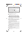
Chauvin-Arnoux CA5005 Manuale del proprietario
- Tipo
- Manuale del proprietario

1
■■
■■
■MULTIMETRE
■■
■■
■MULTIMETER
■■
■■
■MULTIMETER
■■
■■
■MULTIMETRO
■■
■■
■MULTIMETRO
FRANCAIS Notice de fonctionnement
ENGLISH User's manual
DEUTSCH Bedienungsanleitung
ITALIANO Libretto d'Istruzioni
ESPANOL Manual de Empleo
C.A 5005

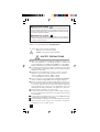
Signification du symbole
ATTENTION ! Consulter la notice de fonctionnement avant d'utili-
ser l'appareil. Dans la présente notice de fonctionnement, les
instructions précédées de ce symbole, si elles ne sont pas bien
respectées ou réalisées, peuvent occasionner un accident corpo-
rel ou endommager l'appareil et les installations.
Signification du symbole
Cet appareil est protégé par une isolation double ou une isolation
renforcée. Il ne nécessite pas de raccordement à la borne de terre
de protection pour assurer la sécurité électrique.
Vous venez d’acquérir un multimètre C.A 5005 et nous vous
remercions de votre confiance.
Pour obtenir le meilleur service de votre appareil:
- lisez attentivement cette notice de fonctionnement,
- respectez les précautions d’emploi.
PRÉCAUTIONS D'EMPLOI
■Ne jamais utiliser sur des réseaux de tension supérieure
à 600 V par rapport à la terre. Ce multimètre, de catégorie de
surtension III, répond aux exigences de fiabilité et de disponibilité
sévères correspondant aux installations fixes industrielles et do-
mestiques (cf. IEC 664-1).
■Utilisation en intérieur dans des environnements de degré de
pollution au plus égal à 2 (cf. IEC 664-1), de température
de -10 à + 55°C et d’humidité relative inférieure à 90%.
■Respecter la valeur et le type des fusibles sous risque de détério-
ration de l'appareil et d'annulation de la garantie.
- Fusible 1 A HPC (6,3 x 32 mm - 500 V - 10 kA)
- Fusible 10 A HPC (6,3 x 32 mm - 500 V - 10 kA)
■Utilisez des accessoires conformes aux normes de sécurité
(IEC 1010-2-031) de tension minimale 600 V et de catégorie de
surtension III.
■Avant toute mesure, s'assurer du positionnement correct des
cordons et du commutateur. Lorsque l'ordre de grandeur d'une
mesure n'est pas connu, placer le commutateur sur le calibre le
plus élevé puis baisser progressivement, si nécessaire, jusqu'au
calibre approprié : la lecture doit s'effectuer, de préférence, dans
les 2/3 supérieurs de l'échelle.
■Ne jamais mesurer de résistances sur un circuit sous tension.
■Lors de mesures d'intensités continues (sans pince ampèremétrique),
interrompre l'alimentation du circuit avant de brancher ou de débran-
cher votre multimètre.
■Pour les mesures d'intensités alternatives utiliser obligatoirement la
minipince MN89 livrée avec le multimètre.
■Pour ouvrir la trappe à pile, il faut obligatoirement déconnecter les
cordons.
■Ne jamais raccorder au circuit à mesurer si la trappe à pile n'est pas
correctement refermée.
2

ENGLISH ............................................................................................... 10
DEUTSCH .............................................................................................. 18
ITALIANO .............................................................................................. 26
ESPANOL .............................................................................................. 34
Page
1-Présentation ........................................................3
2 - Description ..........................................................4
3 - Tensions continues et alternatives (V et ~) ...5
4-Décibels (dB) .......................................................5
5 - Intensités (A et ~) ............................................6
6-Résistances (ΩΩ
ΩΩ
Ω) ...................................................7
7 - Test sonore de continuité [ ] .......................7
8 - Caractéristiques générales ................................7
9 - Accessoires et rechanges (Pour commander) .8
10 - Garantie ................................................................ 8
11 - Maintenance ........................................................9
12 - Annexe .............................................................. 42
SOMMAIRE
...
...
3
1 - PRÉSENTATION
Le multimètre C.A 5005 est destiné aux besoins quotidiens des
professionnels de l'électricité. Il dispose des fonctions suivantes :
- Voltmètre : mesure des tensions (V
...
et ~)
-Ampèremètre continu : mesure des intensités continues en direct
(A
...
)
- Ampèremètre alternatif : mesure des intensités alternatives avec
pince ampèremétrique (A~ )
- Ohmmètre : mesure des résistances (
Ω)
- Test sonore de continuité [ ]
Il permet aussi la mesure de niveaux en décibels (dB), sur les calibres
voltmètre alternatif.
Le cadran est équipé d'un voyant de contrôle des fusibles "Fus" et
d'un voyant "Voltest" pour vérifier l'absence de tension en ohmmètre.
NB : Toujours utiliser des accessoires adaptés à la tension et à la catégorie
de surtension du circuit à mesurer (selon EN 61010).

4
2 - DESCRIPTION
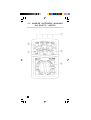
(Voir dessin en § 12 - ANNEXE)
➀➀
➀➀
➀ BORNES
Bornes de sécurité Ø 4 mm
■COM : commun, borne recevant le cordon noir
■
VΩ Ω
Ω Ω
Ω : borne recevant le cordon rouge pour les tensions,
résistances et intensités alternatives avec minipince MN89
■10 A
...
: borne recevant le cordon rouge pour les calibres 10 A
...
■
mA
...
: borne recevant le cordon rouge pour les calibres mA
...
➁➁
➁➁
➁ AFFICHEUR ANALOGIQUE
Le cadran comprend 6 échelles :
■2 échelles noires, avec miroir antiparallaxe,
pour les V
...
et ~ (0.100 et 0.30) et pour les A
...
(0.100)
■1 échelle verte pour les Ω (0.10k)
■2 échelles rouges pour les A ~ avec minipince MN89 (0.3 et 0.10)
■1 échelle rouge pour les dB (0.22)
➂➂
➂➂
➂VOYANT "FUS"
Néon de contrôle des fusibles 1 A et 10 A en mesure d'intensité.
Si le voyant "Fus" est allumé, changer le(s) fusible(s) défectueux.
NB : Ce voyant nécessite la présence d'une tension
≥
80 V pour
s'allumer.
➃➃
➃➃
➃VOYANT "VOLTEST"
Témoin de présence de tension en ohmmètre.
Si le voyant "Voltest" s'allume : présence d'une tension U > 15 V .
Débrancher les cordons et couper la tension avant de procéder à
la mesure de la résistance.
➄➄
➄➄
➄COMMUTATEUR
Commutateur 24 positions pour sélectionner les fonctions et
calibres.

5
(1) R spécifique :
6,32 kΩ/V
(2) En % de
la fin d'échelle
(3) De 20 Hz à ...
(4) Pendant
15 secondes
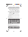
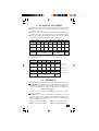
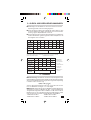
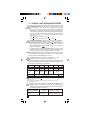
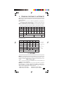
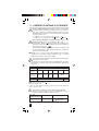
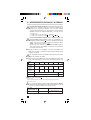
3 - TENSIONS CONTINUES ET ALTERNATIVES
■Raccorder les cordons au multimètre et se brancher en parallèle
sur le circuit à contrôler.
■Lorsque l'ordre de grandeur n'est pas connu, placer le commutateur
sur le calibre le plus élevé puis baisser progressivement jusqu'au
calibre approprié.
■Pour obtenir la tension en V, multiplier la valeur lue sur l'échelle
appropriée par le cœfficient de lecture indiqué dans le tableau.
V
...
100 mV
(1) 1 V 3 V 10 V 30 V 100 V 300 V 1000 V
Echelle 100 100 30 100 30 100 30 100
Cœfficient
de lecture x1(2) x0,01 x0,1 x0,1 x1 x1 x10 x10
Résistance
interne (3)
2 kΩ20 kΩ63,2 kΩ200 kΩ632 kΩ2 MΩ6,32 MΩ6,32 MΩ
Précision
(
4) 2,5 % 1,5 %
Surcharge
admissible 440 V 1000 V(5)
1500 V
(5
(1) Commun au calibre 50
µ
A (2) Lecture directe en mV
(3) R spécifique : 20 k
Ω
/V, sauf calibre 1000 V- R = 6,32 k
Ω
/V
(4) En % de la fin d'échelle (5) Pendant 15 secondes
V
~
10 V 30 V 100 V 300 V 1000 V
Echelle 100 30 100 30 100
Cœfficient
de lecture x0,1 x1 x1 x10 x10
Résistance
interne (1) 63,2 kΩ200 kΩ632 kΩ2 MΩ6,32 MΩ
Précision(2) 3 % 2,5 %
Bande
passante (3) 100 kHz 50 kHz 25 kHz 1 kHz
Surcharge
admissible 1000 V(4) 1500 V(4)
4 - DÉCIBELS
■ Rappel. La mesure d'une tension alternative peut être exprimée en
décibel (symbole dB). Le décibel est le rapport de deux grandeurs ou
niveaux. Le niveau N, en dB d'une tension U a pour expression
mathématique :
()
NdB) UU(log=20 10 0
U0 est la tension de référence de 0,775 V ~ pour une puissance
P0 de 1 mW sur une charge de 600 Ω.
■ Utilisation. Le niveau zéro de l'échelle rouge en dB correspond à
U0=0,775 V pour le calibre 10 V ~. La lecture est directe en dB pour
le calibre 10 V ~ de 0 à +22 dB. Pour les autres calibres, il est
possible de lire en dB (valeur approchée) en ajoutant respectivement:
+10 dB sur le calibre 30 V ~ +20 dB sur le calibre 100 V ~
+30 dB sur le calibre 300 V ~ +40 dB sur le calibre 1000 V ~

6
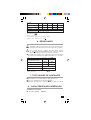
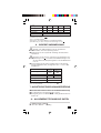
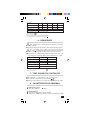
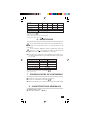
5 - INTENSITÉS CONTINUES ET ALTERNATIVES
Pour les intensités continues : toujours interrompre le circuit
à contrôler avant de connecter le multimètre sur le circuit. Si le
voyant "Fus" est allumé, changer le(s) fusible(s) défectueux
(Rappel : tension minimum de 80 V). Raccorder les cordons au
multimètre et se brancher en série dans le circuit avec :
- le cordon rouge dans la borne "mA
...
", jusqu'à 1 A
...
- le cordon rouge dans la borne "10 A
...
", de 1 A
...
à 10 A
...
Pour les intensités alternatives : utiliser obligatoirement la
minipince MN 89 livrée d'origine avec le multimètre. Elle délivre
100 mV
...
pour 1 A~. Mesure possible jusqu'à 240 A~ maxi.
Raccorder la fiche noire de la minipince à la borne "COM" et la
fiche rouge à la borne " ".
Enserrer qu'un seul conducteur avec la minipince MN 89.
Pour les autres caractéristiques de la MN 89, se reporter à sa
notice de fonctionnement.
■Lorsque l'ordre de grandeur n'est pas connu, placer le commutateur
sur le calibre le plus élevé puis baisser progressivement jusqu'au
calibre approprié.
En intensité continue, interrompre l'alimentation du circuit avant
de changer de calibre.
■Pour obtenir l'intensité en mA ou A, multiplier la valeur lue sur
l'échelle apppropriée par le cœfficient de lecture indiqué dans le
tableau.
A
...
50 µA(1) 1 mA 10 mA 100 mA 1 A 10 A
Echelle 100
Cœfficient x 0,5 (2) x 0,01 x 0,1 x 1 x 0,01 x 0,01
de lecture
Tension aux 100 mV 150 mV 180 mV 200 mV 800 mV
bornes (3)
Précision(4) 2,5% 5%
Protection Fusible 1 A HPC Fus. 10 A
HPC
Limitation 10 min. de marche, 5 min. d'arrêt jusqu'à +40°C maxi.
(1) Commun au calibre 100 mV
...
(2) Lecture en µA
(3) Sans les cordons. Résistance de la paire de cordons fournis : environ 70 m
Ω.
(4) En % de la fin d'échelle.
Au delà de 200 A~ (calibre nominal de la pince MN 89) limiter le
temps d'utilisation. Ne pas utiliser la minipince sur un réseau de
tension supérieure à 600 V par rapport à la terre
.
A~ avec I ≤ 200 A~ 200 A~ < I ≤ 240 A~
minipince MN 89
Fonctionnement Permanent
(1)
10 min de marche
10 min d'arrêt
(1) Avec une fréquence F
≤
1 kHz et un facteur de crête de FC < 3

7
A~ avec 3 A 10 A 30 A 100 A 300 A
(1)
minipince MN 89
Echelle
(2)
3103103
Cœff. de lecture x 1 x 1 x 10 x 10 x 100
Précision
(3)
10% 5% 2,5%
(4)
Protection Assurée avec la minipince MN 89
(5)
(1) Calibre limité à 240 A~ maxi par la minipince MN 89
(2) Repérée par " "
(3) En % de la fin d'échelle
(4) Jusqu'à 200 A~ calibre nominal dela minipince MN 89
(5) Mesurer 240 A~ équivaut à mesurer 24 V
...
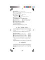
6 - RÉSISTANCES
Ne jamais contrôler une résistance sur un circuit sous tension.
■Se brancher aux bornes du circuit ou du composant à contrôler.
Si le voyant "Voltest" s'allume, présence d'une tension
U > 15 V . Débrancher immédiatement les cordons et couper la
tension avant de procéder à la mesure de résistance.
■Pour obtenir la résistance en Ω, multiplier la valeur lue sur l'échelle
Ω (verte) par le cœfficient du calibre sélectionné : x 1 ou x 100.
Ωx 1(1) x 100
Etendue de mesure 5 Ω à500 Ω à
10 kΩ1 MΩ
Résistance interne 140 Ω14 kΩ
Courant fin d'échelle 10 mA 100 µA
Précision(2) 10%
Surcharge admissible 440 V
(1) Commun à la fonction test sonore de continuité
(2) En % à mi-échelle
7 - TEST SONORE DE CONTINUITÉ
■Raccordement et caractéristiques : idem Résistances
■Placer le commutateur sur la fonction x 1
■Emission d'un bip sonore continu pour une résistance R < 50 Ω
8 - CARACTÉRISTIQUES GÉNÉRALES
8-1 Dimensions et masse
■56 x 105 x 160 mm ■500 g

8
8-2 Alimentation
■Une pile 9 V (type 6F22 ou 6LF22 alcaline)
■
Autonomie : 10 000 mesures de 10 secondes avec pile alcaline LR6
8-3 Conditions climatiques
■
Température :
utilisation : -10°C à +55°C / stockage : -40°C à +70°C
■Humidité relative :
utilisation : ≤ 90 % HR / stockage : ≤ 95 % HR
■Altitude : utilisation < 2000 m
8-4 Conformité aux normes internationales
8-4-1 Sécurité électrique (NF EN 61010-1)
■Double isolation : ■Catégorie d'installation : III
■Degré de pollution : 2 ■Tension assignée : 600 V
8-4-2 Compatibilité électromagnétique
Emission et immunité (NF EN 61326-A1 Ed. 98)
8-4-3 Protection mécanique
■Degré d'étancheité (NF EN 60529, Ed 92) : indice de protection IP 53
9 - POUR COMMANDER
Utiliser les désignations et références ci-dessous.
C.A 5005 ..................................................................... P01.1965.23E
Livré avec une minipince MN 89 et sa notice de fonctionnement,
un jeu de 2 cordons à pointe de touche, une pile 9 V
et cette notice de fonctionnement
Accessoires et rechanges
■Sacoche de transport (240 x 230 x 70 mm) ......... P01.2980.33
■Etui de transport (220 x 180 x 75 mm) ................... P01.2980.36
■Jeu de 2 cordons
à pointe de touche (NF EN 61010)......................... P01.2980.84
■Jeu de 10 fusibles 1 A HPC (6,3 x 32 mm ) ........... P01.2970.39
■Jeu de 10 fusibles 10 A HPC (6,3 x 32 mm )........ P01.2970.38
Différents accessoires de mesure élargissent le champ d'applications
ou confèrent de nouvelles fonctions à votre multimètre.
Documentation sur demande.
NB : Toujours utiliser des accessoires adaptés à la tension et à la
catégorie de surtension du circuit à mesurer (selon NF EN 61010).
10 - GARANTIE
Notre garantie s’exerce, sauf stipulation expresse, pendant trois ans
après la date de mise à disposition du matériel (extrait de nos
Conditions Générales de Vente, communiquées sur demande).

9
11 - MAINTENANCE
Pour la maintenance, utilisez seulement les pièces de
rechange qui ont été spécifiées. Le fabricant ne pourra être
tenu pour responsable de tout accident survenu suite à une
réparation effectuée en dehors de son service après-vente
ou des réparateurs agréés.
11-1 Remplacement de la pile et des fusibles
Pour votre sécurité, il faut obligatoirement déconnecter les
cordons du multimètre pour ouvrir la trappe à pile.
■Pour ouvrir la trappe, tourner la vis 1/4 de tour, dans le sens inverse
des aiguilles d'une montre, à l'aide d'une pièce ou d'un tournevis.
■Remplacer la pile usagée par une pile 9 V (type 6F22 ou 6LF22).
■Remplacer les fusibles défectueux en respectant leur valeur et
leur type :
- Fusible 1 A HPC (6,3 x 32 mm - 500 V - 10 kA)
- Fusible 10 A HPC (6,3 x 32 mm - 500 V - 10 kA)
■Remonter la trappe avant d'utiliser le multimètre.
11-2 Stockage
Si le multimètre n'est pas mis en service pendant une durée dépassant
60 jours, enlever la pile et stocker la séparément.
11-3 Nettoyage
■Le multimètre doit être déconnecté de toute source électrique.
■Pour nettoyer le boîtier, utiliser un chiffon légèrement imbibé
d'eau savonneuse. Essuyer avec un chiffon humide. Ensuite,
sécher rapidement avec un chiffon ou de l'air pulsé.
11-4 Vérification métrologique
Comme tous les appareils de mesure ou d’essais, une
vérification périodique est nécessaire.
Pour les vérifications et étalonnages de vos appareils, adressez vous
à nos laboratoires de métrologie accrédités par le COFRAC ou aux
agences MANUMESURE.
Renseignements et coordonnées sur demande :
Tél. : 02 31 64 51 43 Fax : 02 31 64 51 09
11-5 Réparation sous garantie et hors garantie
Adressez vos appareils à l'une des agences régionales
MANUMESURE, agréées CHAUVIN ARNOUX
Renseignements et coordonnées sur demande :
Tél. : 02 31 64 51 43 Fax : 02 31 64 51 09
11-6 Réparation hors de France métropolitaine
Pour toute intervention sous garantie ou hors garantie, retournez
l’appareil à votre distributeur.

Meaning of the symbol
Thank you for purchasing a C.A 5005 Multimeter.
To get the best service from this instrument:
- read this user’s manual carefully,
- respect the safety precautions detailed.
SAFETY PRECAUTIONS
■Never use on networks at a voltage above 600 V in relation to the
earth. This multimeter of overvoltage category III, satisfies the
severe requirements of reliability and availability corresponding to
industrial and domestic permanent installations (c.f. IEC 664-1).
■Use indoors in environments of degree of pollution at most equal
to 2 (c.f. IEC 664-1), of temperature from -10 to +55°C and of relative
humidity less than 90%.
■Respect the value and the type of fuses or there is a risk of
damage to the instrument and cancellation of the warranty.
- Fuse 1 A HBC (6.3 x 32 mm - 500 V - 10 kA)
- Fuse 10 A HBC (6.3 x 32 mm -500 V -10 kA)
■Use accessories in conformity with safety standards (NF EN 61010-
2-031) of minimum voltage 600 V and overvoltage category III.
■Before any measurement, check the leads and the switch are in
the correct position. When the order of magnitude of a measurement
is not known, place the selector switch on the highest range then
lower progressively, if necessary, to the appropriate range: the
reading must be made, preferably, in the upper 2/3 of the scale.
■Never measure resistances on a live circuit.
■For DC current measurements (without current clamp), switch off
the power supply of the circuit before connecting or disconnecting
your multimeter.
■■
■■
■For AC current measurements the use of the MN89 miniclamp
supplied with the multimeter is mandatory.
■■
■■
■To open the battery compartment, the leads must be disconnected.
■■
■■
■Never connect to the circuit to be measured if the battery
compartment is not correctly closed.
Warning ! Please refer to the User’s Manual before using the instrument.
In this User’s Manual, the instructions preceded by the above symbol, should
they not be carried out as shown, can result in a physical accident or damage
the instrument and the installations.
Meaning of the symbol
This device is protected by a double insulation or by a reinforced
insulation. No linking is required from the protection earth terminal
to ensure electrical safety.
10

11
Page
1 - Presentation ....................................................... 11
2 - Description ......................................................... 12
3 - DC and AC voltages (V DC and AC) ................ 13
4 - Decibels (dB) ..................................................... 13
5 - Currents (A DC and AC) ................................... 14
6 - Resistances (Ω) ................................................ 15
7 - Continuity sound test [ ] .............................. 15
8 - General specifications ....................................... 15
9 - Accessories and spares (To order) ................. 16
10 - Warranty ............................................................ 16
11 - Maintenance ...................................................... 17
12 - Appendix ............................................................ 42
CONTENTS
1 - PRESENTATION
The C.A 5005 multimeter is designed for the daily needs of
professionals in electricity. It has the following functions:
- Voltmeter: voltage measurements (V DC and AC)
- DC ammeter: measurement of DC currents directly (A DC)
- AC ammeter: measurement of AC currents with current clamp
(A AC )
- Ohmmeter: resistance measurements (ΩΩ
ΩΩ
Ω)
- Continuity sound test [ ]
It also allows the measurement of decibel levels (dB), on the AC
voltmeter ranges.
The dial has a fuse test light (Fus.) and “Voltest” light to check the
absence of voltage on ohmmeter.
NB: Always use accessories suited
to
the voltage and the overvoltage
category of the circuit
to
measure (to NF EN 61010).

12
5 SWITCH
Switch with 24 positions to select the functions and ranges.
(See drawing in § 12 - APPENDIX)
2 ANALOGUE DISPLAY
The dial comprises 6 scales:
■2 black scales, with antiparallax mirror,
for V DC and AC (0.100 and 0.30) and for A DC (0.100)
■1 green scale for Ω (0.10k)
■2 red scales for A AC with miniclamp MN 89 (0.3 and 0.10)
■1 red scale for dB (0.22)
1 TERMINALS
∅ 4 mm safety terminals
■COM: common, terminal that receives the black lead
■VΩ Ω
Ω Ω
Ω : terminal that receives the red lead for voltages,
resistances and AC voltages with miniclamp MN 89
■■
■■
■10 A DC: terminal that receives the red lead for the 10 A DC ranges
■■
■■
■mA DC: terminal that receives the red lead for the mA DC ranges
2 - DESCRIPTION
3 “FUS” LIGHT
Neon for testing the 1 A and 10 A fuses on current measurement.
If the «Fus.» light is lit, change the faulty fuse(s).
NB: This light requires the presence of a voltage
≥
80 V to come on.
4 “VOLTEST” LIGHT
Voltage presence light on ohmmeter.
If the «Voltest» light comes on: presence of a voltage
U > 15 V AC/DC. Unplug the leads and cut off the voltage
before making the resistance measurement.

13
4 - DECIBELS
■■
■■
■ Reminder. The measurement of an AC voltage can be expressed
in decibels (symbol dB). The decibel is the ratio of two quantities or
levels. Level N, in dB, of a voltage U has the mathematical expression:
Uo is the reference voltage of 0.775 V AC for a power Po of 1 mW
on a load of 600 Ω.
■■
■■
■ Use. Zero level of the red scale in dB corresponds to Uo = 0.775
for the 10 V AC range. The reading is direct in dB for the 10 V AC range
from 0 to +22 dB. For the other ranges, it is possible to read in dB (near
value) by adding respectively:
+10dB on the 30 V AC range +20dB on the 100 V AC range
+30dB on the 300 V AC range +40dB on the 1000 V AC range
3 -
DC AND AC VOLTAGES
■Connect the leads to the multimeter and connect in parallel to the
circuit to be tested.
■When the order of magnitude is not known, place the switch on the
highest range then progressively lower to the appropriate range.
■To get the voltage in V, multiply the value read on the appropriate
scale by the reading cœfficient shown in the table.
(1) Common to the 50 µA range (2) Direct reading in mV
(3) Specific R: 20 kΩ/V, except range 1000 V-R = 6.32 kΩ/V
(4) In % of the end of scale (5) For 15 seconds
(1) Specific R:
6.32 kΩ/V
(2) In % of
the end of scale
(3) From 20 Hz to ...
(4) For 15 seconds
()
NdB) UU(log=20 10 0
V
AC
10 V 30 V 100 V 300 V 1000 V
Scale 100 30 100 30 100
Reading
cœfficient x0,1 x1 x1 x10 x10
Internal
resistance (1) 63,2 kΩ200 kΩ632 kΩ2 MΩ6,32 MΩ
Accuracy(2) 3 % 2,5 %
Bandwidth
(3) 100 kHz 50 kHz 25 kHz 1 kHz
Permitted
overload 1000 V(4) 1500 V(4)
V DC
100 mV
(1) 1 V 3 V 10 V 30 V 100 V 300 V 1000 V
Scale 100 100 30 100 30 100 30 100
Reading
cœfficient x1(2) x0,01 x0,1 x0,1 x1 x1 x10 x10
Internal
resistance (3)
2 kΩ20 kΩ63,2 kΩ200 kΩ632 kΩ2 MΩ6,32 MΩ6,32 MΩ
Accuracy
(
4) 2,5 % 1,5 %
Permitted
overload 440 V 1000 V(5)
1500 V
(5)

14
■When the order of magnitude is not known, place the switch on the
highest range then progressively lower to the appropriate range.
On DC current, switch off the power supply to the circuit ill
before changing range.
■To get the current in mA or A, multiply the value read on the
appropriate scale by the reading cœfficient shown in the table.
A
...
50 µA(1) 1 mA 10 mA 100 mA 1 A 10 A
Scale 100
Reading x 0.5 (2) x 0.01 x 0.1 x 1 x 0.01 x 0.01
cœfficient
Voltage at 100 mV 150 mV 180 mV 200 mV 800 mV
terminals (3)
Accuracy(4) 2.5% 5%
Protection Fuse 1 A HPC Fuse 10 A
HBC
5 -
DC AND AC CURRENTS
For DC currents: Always switch off the circuit to test before
connecting the multimeter to the circuit. If the «Fus.» light
comes on, change the faulty fuse(s) (Reminder: minimum
voltage of 80 V). Connect the leads to the multimeter and
connect in series to the circuit with:
-the red lead in the «mA DC» terminal, up to 1 A DC
-the red lead in the «10 A DC» terminal, from 1 A DC to 10 A DC
For AC currents: mandatory use of the MN89 miniclamp
originally supplied with the multimeter. It outputs 100 mV DC for
1 A AC. Measurement possible up to 240 A AC max. Connect
the black plug of the miniclamp to the «COM» terminal and the
connect the red plug to the " " terminal.
Clamp on only one conductor with the MN 89. For the other
specifications of the MN 89, refer to its user manual.
Limitation 10 min On, 5 min Off up to +40°C max
(1) Commonlolhe 100 mVDC range
(2) Reading in µA.
(3) Without the leads Resistance of thepair of leads supplied: approx. 70 m
(4) ln % of the end of scale
Above 200 A AC (nominal range of the MN 89 miniclamp) limit
the time of use. Do not use the miniclamp on a network with a
voltage greater than 600 V in relation to the earth.
A AC with I ≤ 200 A~ 200 A~ < I ≤ 240 A~
miniclamp MN 89
Operating Permanent
(1)
10 min On
10 min Off
(1) With a frequency F
≤
1 kHz and a crest factor FC < 3

15
A~ with 3 A 10 A 30 A 100 A 300 A (1)
miniclamp MN 89
Scale(2) 3103103
Reading cœfficient x 1 x 1 x 10 x 10 x 100
Accuracy(3) 10% 5% 2.5%(4)
Protection ensured by the miniclamp MN89 (5)
(1) Range limitedto240AAC max by the miniclamp MN 89
(2) Marked with " "
(3) In %ofthaend of scale
(4) Up to 200 A AC nominal range of the MN 89 miniclamp
(5) Measuring240AACisequivalenttomeasuring24 VDC
■To get the resistance in Ω, multiply the reading on the Ω scale
(green) by the cœfficient of the selected range: x 1 or x 100.
Ωx 1(1) x 100
Measurement 5 Ω to 500 Ω to
extend 10 kΩ1 MΩ
Internal resistance 140 Ω14 kΩ
End of scale current 10 mA 100 µA
Accuracy(2) 10%
Permitted overload 440 V
(1) Common to the continuily sound test function
(2) In % at mid-scale
7 - CONTINUITY SOUND TEST
■Connection and specifications: idem Resistances
■Place the selector switch on the x 1 function
■Continuous audible beep emitted for a resistance R < 50 Ω
6 - RESISTANCES
Never test a resistance on a live circuit.
If the “Voltest” light comes on, presence of a voltage U > 15 V
AC/DC. Unplug the leads immediately and cut off the voltage
before making the resistance measurement.
■Connect to the terminals of the circuit or the component to test.
8 - GENERAL SPECIFICATIONS
8-1 Dimensions and weight
■56 x 105 x 160 mm ■500 g

16
Use the designations and references below.
C.A 5005 .................................................................... P01.1965.23E
Supplied with a pair of leads with prods,
1 battery 9 V and this User’s manual.
Accessoires et rechanges
■Shoulder bag (240 x 230 x 70 mm) ....................... P01.2980.33
■Carrying holster (220 x 180 x 75 mm) .................. P01.2980.36
■Pair of leads with test prods (NF EN 61010) ........ P01.2980.84
■Set of 10 fuses 1 A HBC (6.3 x 32 mm) ................ P01.2970.39
■Set of 10 fuses 10 A HBC (6.3 x 32 mm) .............. P01.2970.38
Different measurement accessories widen the field of application or
confer new functions on your multimeter.
Documentation on request.
NB: Always use accessories suited to the voltage and the overvoltage
category of the circuit to measure (to NF EN 61010).
Our guarantee is applicable for three years after the date on which the
equipment is made available (extract from our General Conditions of
Sale, available on request).
10 - WARRANTY
8-2 Power supply
■One battery 9 V (type 6F22 or 6LF22 alkaline)
■Battery life:
- 10,000 measurements of 10 seconds with alkaline battery LR6
8-3 Environmental conditions
■Temperature: use: -10°C to +55°C / storage: -40°C to +70°C
■Relative humidity:
use: ≤ 90% RH / storage: ≤ 95% RH
■Altitude: use < 2000 m
8-4 Conformity with international standards
8-4-1 Electrical safety (NF EN 61010-1, ed. 95)
■Double insulation : ■Installation category: III
■Degree of pollution: 2 ■Rated voltage: 600 V
8-4-2 Electromagnetic compatibility
Emission and Immunity (NF EN 61326-A1, ed. 98)
8-4-3 Mechanical protection
■Degree of watertightness (NF EN 60529, ed 92): protection index IP 53
9 - TO ORDER

17
11-2 Storage
If the multimeter is not put into service for a time exceeding 60 days,
remove the batteries and store them separately.
11-3 Cleaning
■The multimeter must be disconnected from any electrical source.
■To clean the case, use a cloth slightly moistened with soapy water.
Rinse with a damp cloth. Then, dry rapidly with a cloth or in a hot
air stream.
11-4 Metrological check
It is essential that all measuring instruments are regularly
calibrated.
For checking and calibration of your instrument, please contact our
accredited laboratories (list on request) or the Chauvin Arnoux
subsidiary or Agent in your country.
11-5 Repair
Repairs under or out of guarantee: please return the product to your
distributor.
11 - MAINTENANCE
For maintenance, use only specified spare parts. The
manufacturer will not be held responsible for any accident
occurring following a repair done other than by its After
Sales Service or approved repairers.
11-1 Replacing the battery and the fuses
For your safety the leads must be disconnected from the
multimeter before the battery cover is opened.
■To open the cover, turn the screw 1/4 turn, anti-clockwise, using
a coin or a screwdriver.
■Replace the dead battery by one 9 V battery (type 6F22 or 6LF22).
■Replace the faulty fuses respecting their value and their type:
- Fuse 1 A HBC (6.3 x 32 mm - 500 V - 10 kA)
- Fuse 10 A HBC (6.3 x 32 mm - 500 V - 10 kA)
■Refit the cover before using the multimeter.

Bedeutung des Zeichens
Sie haben ein Multimeter C.A 5005 gekauft und wir bedanken uns
für das entgegengebrachte Vertrauen.
Um mit Ihrem Gerät die besten Ergebnisse zu erzielen:
- lesen Sie bitte aufmerksam die vorliegende
Bedienungsanleitung
- beachten Sie bitte die Sicherheitshinweise.
SICHERHEITSHINWEISE
■Das Multimeter niemals an Stromkreisen mit einer Spannung von
mehr als 600 V gegenüber Erde benutzen. Das Multimeter besitzt
die Überspannungsklasse III und erfüllt damit die strengen
Zuverlässigkeits- und Verfügbarkeitsanforderungen für fest
eingebaute Industrie- und Haushalts-Elektroinstallationen (vgl.
IEC-Norm 644-1).
■Das Multimeter nur in Innenräumen in Umgebungen mit einer
Fremdschichtklasse von höchstens 2 (vgl. IEC-Norm 664-1), bei
Temperaturen zwischen -10° und +55°C und bei einer relativen
Luftfeuchte von weniger als 90% benutzen.
■Ausschließlich Sicherungen mit der angegebenen Nennstromstärke
verwenden, da das Gerät sonst Schaden nehmen kann und die
Garantie erlischt:
- 1 A Hochleistungssicherung (6,3 x 32 mm - 500 V - 10 kA)
- 10 A Hochleistungssicherung (6,3 x 32 mm - 500 V - 10 kA)
■Ausschließlich Meßzubehör verwenden, das die Sicherheitsnorm
EN 61010-2-031 erfüllt, mit einer Mindestspannung von 600 V und
für Überspannungskategorie III.
■Vor jeder Messung auf den richtigen Anschluß der Meßschnüre
und die richtige Stellung des Drehschalters achten. Wenn die
Größenordnung einer Meßgröße nicht bekannt ist, den
Drehschalter auf den höchsten Meßbereich stellen und stufenweise
herunterschalten, bis die geeignete Empfindlichkeit erreicht ist: der
abgelesene Wert sollte vorzugsweise in den oberen 2/3 der
Meßskala liegen.
■Niemals eine Widerstandsmessung an einem unter Spannung
stehenden Stromkreis vornehmen.
■Für Wechselstrommessungen ausschließlich den Mini-Zangen-
stromwandler MN89 benutzen, der dem Multimeter beiliegt.
■Vor Öffnen des Batteriefachs müssen sämtliche Meßleitungen
abgezogen werden.
■Das Multimeter niemals an einen Meßkreis anschließen solange
das Batteriefach nicht einwandfrei verschlossen ist.
ACHTUNG ! Beachten Sie vor Benutzung des Gerätes die Hinweise in der
Bedienungsanleitung. Falls die in der vorliegenden Bedienungsanleitung
nach diesem Zeichen erscheinenden Anweisungen nicht beachtet bzw. nicht
ausgeführt werden, können Verletzungen verursacht bzw. das Meßgerät und
die Anlage beschädigt werden.
Bedeutung des Zeichens
Das Gerät ist schutzisoliert bzw. durch eine verstärkte Isolierung geschützt.
Ein Anschluß an einen Erdleiter ist zur Gewährleistung der elektrischen
Sicherheit nicht erforderlich.
18

Seite
1-Gerätevorstellung .............................................. 19
2 - Gerätebeschreibung ......................................... 20
3 - Gleich- und Wechselspannungen (V und ~) .. 21
4 - Dezibel (dB) ....................................................... 21
5 - Gleich- und Wechselströme (A und ~) ......... 22
6 - Widerstandsmessung (Ω) ................................. 23
7 - Akustische Durchgangsprüfung [ ] ............. 23
8 - Allgemeine technische Daten ............................ 23
9 - Bestellangaben, Zubehör, Ersatzteile ............... 24
10 - Garantiebedingungen ........................................ 24
11 - Wartung, Reparatur ........................................... 25
12 - Anhang ............................................................... 42
INHALTSVERZEICHNIS
1 - GERÄTEVORSTELLUNG
Das Multimeter C.A 5005 wurde besonders für den anspruchsvollen
täglichen Einsatz bei Profis der Elektrotechnik entwickelt. Es
besitzt die folgenden Meßfunktionen:
-Messung von Gleich- und Wechselspannungen (V
...
und -)
-direkte Messung von Gleichströmen (A
...
)
-Messung von Wechselströmen mit Zangenstromwandler
(A~ )
-Messung von Widerständen (Ω)
-Akustische Durchgangsprüfung [ ]
In den Wechselspannungsbereichen ist auch die Messung von
Spannungspegeln in Dezibel (dB) möglich.
Das Gerät ist mit Kontrolleuchten für den Zustand der Sicherungen
(Fus) und für die Spannungsfreiheit vor Widerstandsmessungen
(Voltest) ausgerüstet.
Hinweis: Verwenden Sie ausschließlich Zubehör, dessen zulässige
Spannung und Überspannungskategorie mit dem zu messenden
Stromkreis übereinstimmt (vgl. NF EN 61010).
...
...
19

20
5 FUNKTIONSSCHALTER
Drehschalter mit 24 Stellungen zur Auswahl der Meßfunktion und
des Meßbereichs.
(siehe Abb. in Abschn. 12. Anhang)
2 ANALOGANZEIGE
Die Anzeige ist in 6 Skalen unterteilt:
■2 schwarze Skalen mit Spiegel für parallaxenfreie Ablesung in den
V
...
und V~ Bereichen (0 bis 100)
■1 grüne Skala für die Ω-Messung (0 bis 10 kΩ)
■2 rote Skalen für die A~ -Bereiche mit der Minizange MN89
(0 bis 30 und 0 bis10)
■1 rote Skala für die dB-Messung (0 bis 22)
1 ANSCHLUSSBUCHSEN
Ø 4 mm Sicherheitsbuchsen
■COM : COMMON bzw. MASSE-Buchse für schwarze Meßleitung
■
VΩΩ
ΩΩ
Ω :
Buchse für rote Meßleitung bei Spannungs- und
Widerstandsmessungen mit der Minizange MN89
■10 A
...
: Buchse für rote Meßleitung in den Meßbereichen 10 A
...
■
mA
...
:
Buchse für rote Meßleitung in dem mA-Meßbereichen
2 - GERÄTEBESCHREIBUNG
3 KONTROLLEUCHTE "FUS"
Neon-Kontrolleuchte für den Zustand der 1 A und 10 A- Sicherungen
bei Strommessungen
Bei Aufleuchten der FUS-Lampe ist die Sicherung defekt
und muß ausgewechselt werden.
Hinweis: Die Lampe leuchtet nur, wenn eine Spannung von
≥≥
≥≥
≥
80 V
anliegt.
4 KONTROLLEUCHTE "VOLTEST"
Die Leuchte zeigt an, daß bei Widerstandsmessungen eine
Fremdspannung anliegt.
Bei Aufleuchten der Voltest-Lampe liegt eine Spannung
U > 15 V
an. Entfernen Sie die Meßleitungen und schalten
Sie die Spannung vor Messung des Widerstands ab.
La pagina si sta caricando...
La pagina si sta caricando...
La pagina si sta caricando...
La pagina si sta caricando...
La pagina si sta caricando...
La pagina si sta caricando...
La pagina si sta caricando...
La pagina si sta caricando...
La pagina si sta caricando...
La pagina si sta caricando...
La pagina si sta caricando...
La pagina si sta caricando...
La pagina si sta caricando...
La pagina si sta caricando...
La pagina si sta caricando...
La pagina si sta caricando...
La pagina si sta caricando...
La pagina si sta caricando...
La pagina si sta caricando...
La pagina si sta caricando...
La pagina si sta caricando...
La pagina si sta caricando...
La pagina si sta caricando...
La pagina si sta caricando...
-
 1
1
-
 2
2
-
 3
3
-
 4
4
-
 5
5
-
 6
6
-
 7
7
-
 8
8
-
 9
9
-
 10
10
-
 11
11
-
 12
12
-
 13
13
-
 14
14
-
 15
15
-
 16
16
-
 17
17
-
 18
18
-
 19
19
-
 20
20
-
 21
21
-
 22
22
-
 23
23
-
 24
24
-
 25
25
-
 26
26
-
 27
27
-
 28
28
-
 29
29
-
 30
30
-
 31
31
-
 32
32
-
 33
33
-
 34
34
-
 35
35
-
 36
36
-
 37
37
-
 38
38
-
 39
39
-
 40
40
-
 41
41
-
 42
42
-
 43
43
-
 44
44


Chauvin-Arnoux CA5005 Manuale del proprietario
- Tipo
- Manuale del proprietario
in altre lingue
Documenti correlati
-
CHAUVIN ARNOUX C.A 5001 Manuale utente
-
 Chauvin-Arnoux CA5001 Manuale del proprietario
-
 Chauvin-Arnoux CA5230G Manuale del proprietario
-
 Chauvin-Arnoux CA5011 Manuale del proprietario
-
CHAUVIN ARNOUX C.A 5260G Manuale utente
-
 Chauvin-Arnoux CA5205G Manuale del proprietario
-
-
Metrix CA23-H Manuale del proprietario
-
 Chauvin-Arnoux CA6513 Manuale del proprietario
-
 Chauvin-Arnoux CAC112 Manuale utente


