CAME Troubleshooting XIP Guida d'installazione
- Tipo
- Guida d'installazione

GUIDA RICERCA GUASTI
TROUBLESHOOTING GUIDE
12 - 2018

2
VSE/301
B OUT
B IN
A
M2
M1
DVC/01
+
BOUT
-
MITHO
M1
M2
AL
B
MM
Ð
+
SW4
OPHERA/B
SW1
BUS
LOCAL
SW2
B
YKP/301+YV(YVC)+YP3
-
+
BUS
LOCAL
SW9
-
-
-
M2
VAS/100.30
A
1
2
1
2
M1
M1
B
-
+
AL
M1
M1
SW3
Ð
+18V
230V
PRI
SEC
+ 18V –
230V
230V 50Hz 18V 10VA
VAS/100MH
Presentazione
Introduction
La guida riporta una serie di informazioni e una check-list per supportare l’installazione e la ricerca guasti del sistema XIP Came. Per un corretto utilizzo, si racco-
manda di eseguire i test secondo le indicazioni riportate.
This guide includes information and a checklist to aid in installation and troubleshooting for XIP Came systems. For proper use, please carry out the tests according
to the instructions provided here.
Individuazione del sistema videocitofonico
Identification of video-entry system
Per un corretto uso della check-list è necessario riconoscere con
esattezza il tipo di configurazione che si sta analizzando.
Riportiamo alcune informazioni caratterizzanti i diversi sistemi.
In un impianto di videocitofonia si devono gestire tre tipi di
segnali: il segnale video, il segnale audio e i segnali di controllo/
gestione del sistema. Per far questo, il sistema XIP utilizza tre
tecniche diverse: la tecnologia proprietaria X1 per la montante,
il CAN-bus per la gestione dei dati verso i posti esterni XIP e la
distribuzione Ethernet con protocollo IP per il collegamento dei
vari gateway di impianto.
La tecnologia X1 gestisce i tre segnali (audio + video + dati) su
un unico doppino, controllando tutti i derivati e i relativi acces-
sori di montante della gamma X1 (monitor, cornette, selettori
intercomunicanti). Questa tecnologia è utilizzata sia dalle targhe
X1 (DVC/01,DC/01, LVC/01...) che dall’alimentatore di impianto
X1 (VA/01).
For correct use of the checklist, you need to know exactly what
type of configuration you are dealing with.
Here is some information that characterizes the various systems.
A video entry control system should be able to manage three
types of signals:
a video signal, an audio signal and the system control signals.
In order to do this, the XIP system uses three different tech-
niques: X1 proprietary technology for the riser, the CAN-bus for
data management of XIP entry panel and the ethernet distribu-
tion with IP protocol for the connections of the gateways inside
the plant.
The X1 technology manages the three signals (audio + video
+ data) on a single twisted pair, controlling all extensions and
related accessories of the X1 range (monitors, receivers, intercom
selectors). This technology is used both by the X1 entry panels
(DVC/01,DC/01, LVC/01...) and by the X1 (VA/01) power supplier.
LITHOS
+
BOUT
-
B
-
+
BUS
LOCAL
SW9
-
-
SW3 SW8
M2
+
Ð
M2
M1
B
-
+
BUS
LOCAL
SW9
SW3 SW8
M1
B
-
+
-
+
BUS
LOCAL
SW9
SW3 SW8
SLAVE
SLAVE
MASTER
M1
M1
VAS/101
A
YVL301
YVCL301
YVL301
YVCL301
YVL301
YVCL301
-
+
-
+
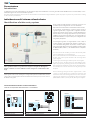
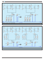
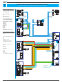
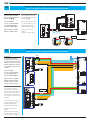
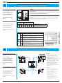
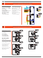
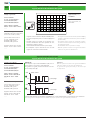
Impianto monoblocco X1 (solo tecnologia X1).
Tutti i segnali in montante sono gestiti su unico doppino. Il collegamento alla targa X1
DVC/01 è effettuato con un cavo VCM/2D contenente il doppino X1 e l’alimentazione alla
targa.
X1 video entry system single-block (X1 Came Technology only).
All the signals on the riser are managed on a single twisted pair. The VCM/2D cable, which is
composed by one twisted pair for the X1 bus and two wires for the power, is used to connect
the DVC/01 entry panel.
B
12
OUT
SW2
SW4
SW3
SW0
XDV/304
34
IN
VSE/301
BOUT
BIN
A
M2
ALCUNE APPARECCHIATURE GESTITE CON TECNOLOGIA X1
SOME OF THE EQUIPMENT MANAGED WITH X1 TECHNOLOGY
Monitor LYNEA BASIC
LYNEA BASIC monitor
Selettore VSE/301, distributore XDV/304
VSE/301 selector, XDV/304 distributor
Targa videocitofonica DVC/01
DVC/01 video entry panel

3
Il bus CAN (Controller Area Network) per la gestione del bus
dati è utilizzato solo con alimentatore VA/08 e gestisce la logica
di funzionamento tra targhe XIP (DVC/08, DC/08, Digitha A/V,
Digitha audio...), blocchi X1 e relativi accessori di gamma XIP
(selettori ciclici, relè).
Gli altri segnali (audio e video) sono gestiti con doppini dedicati.
Un sistema XIP si caratterizza dall’avere almeno un alimentatore
VA/08 collegato all’impianto.
The CAN bus (Controller Area Network) protocol is used only
with the VA/08 power supplier and manages the operating logic
between XIP entry panels (DVC/08, DC/08, Digitha A/V, Digitha
audio), X1 blocks and XIP range accessories (e.g. relay, cyclical
selector).
The other signals (audio and video) are managed with dedicated
twisted pairs.
An XIP system is therefore characterized by having at least one
VA/08 power supplier connected to the system.
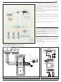
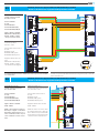
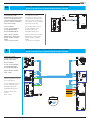
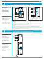
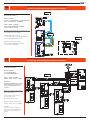
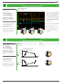
Impianto monoblocco XIP.
Il collegamento alle targhe XIP è effettuata con un cavo VCM/4D
contenente 3 doppini per la gestione dei segnali audio, video e
dati (CAN-bus) più due fili per l’alimentazione alla targa. Il bus
dati è di tipo polarizzato (+D-).
Nell’esempio, un ingresso dell’alimentatore è dedicato alla ge-
stione del selettore ciclico TVCC.
XIP video entry system single-block.
The XIP entry panels are conencted to the system using the
VCM/4D cable which is composed by 3 twisted pairs for the audio,
video, data signals (CAN-bus) and two wires for power. The data
bus is polarized (+D-).
On the drawing sample one power supply input is dedicated to
the CCTV cameras selector.
M4M1
M2
M5
M3
+12V
+D – +V1– +V2 –
A A +D – +V3– +V4 –
A A
M1
CN1
CN4
M2
CN2
A
A
D
V
PROG
DATI 1 2
ON
3
(*)
IN
OUT
MINI USB
SW2
VLS/101
1
2
1
2
ALCUNE APPARECCHIATURE GESTITE VIA CANBUS +D:
SOME OF THE EQUIPMENT MANAGED WITH CANBUS +D:
Posto esterno DVC/08 e alimentatore VA/08
DVC/08 Entry panel and VA/08 power supply
Modulo relè VLS/3
VLS/3 relais module
M4M1
M2
M5
M3
+12V
+D – +V1– +V2 –
A A
+D – +V3– +V4 –
A A
PROG
LR1
LR3
LR2
DATA
PROG
++
DI3 I2 I1 I–
––
NC
NO
C2
NCNO C1
+
–
NC
NO C3
M1
M2 M3
VLS/3
VA/08

4
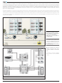
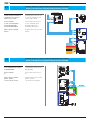
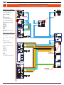
La distribuzione Ethernet è utilizzata come struttura principale per la comunicazione tra tutte le varie sezioni di impianto. Dal lato dorsale, ogni sezione è gestita
da un gateway IP (ETI/XIP) mentre dal lato montante da un VA/08. La piena compatibilità del sistema con il protocollo IP, consente un’estensione pressoché infinita
dell’impianto e permette la trasmissione dati tra i vari siti anche a distanze considerevoli. La struttura LAN permette l’integrazione nel sistema di componenti ag-
giuntivi quali centralini di portineria su PC (XIP/Porter), server per il controllo accessi e i servizi avanzati di portineria (ETI/SER) o derivati IP di terze parti. Si parla in
questo caso di impianti XIP/LAN.
The Ethernet distribution is used as the main back-bone structure for the communication between all the several system’s parts. On the back-bone side the man-
agement is demanded to the IP gateway (ETI/XIP) otherwise on the riser side to the VA/08. The full compatibility of the system with the IP protocol permits an huge
system extention and the data transmittion between different sites located at sizeable distances. The LAN structure allows the additional items integration on the
system like porter switchboards on PC (XIP/Porter), server for the access control and advanced porter services (ETI/SER XIP) or third parties IP receviers. In this case
the system is the XIP/LAN.
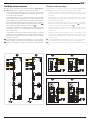
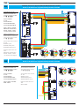
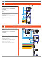
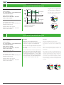
Impianto XIP/LAN. Il collegamento
alla LAN dei vari ETI/XIP e dell’ETI/
SER è effettuata con cavo UTP CAT5.
La connessione tra l’ETI/XIP e il
VA/08 di blocco avviene tramite ca-
vo FLAT dedicato.
XIP/LAN system.
The ETI/XIP and the ETI/SER XIP are
cabled to the LAN using the UTP CAT
5 cable. The ETI/XIP is connected to
the VA/08 power supply through a
dedicated flat cable.
Qui sotto mostriamo uno schema di
impianto contenente alcune appa-
recchiature utilizzate in sistemi XIP/
LAN.
Here below it is shown a diagram
with some devices used on XIP/LAN
systems.
Sezione di impianto XIP/LAN con ETI/SER, ETI/XIP e XIP/Porter
XIP/LAN system section with ETI/SER XIP, ETI/XIP and XIP/Porter

5
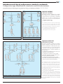
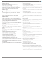
Individuazione del tipo di configurazione: standard o residenziale
Configuration type identification: standard or multi-block structures
Il sistema XIP permette la realizzazione di cinque configurazioni diverse. Le configurazioni si suddividono in due macro famiglie:
The XIP system permits to realize 5 different configurations. The configurations is divided in two families:
Impianti standard
Impianti standard
Gli impianti standard si utilizzano per la villetta
(mono-ingresso) o per la palazzina con più ingres-
si. Questi sistemi sono normalmente caratterizzati
dall’avere solo un canale di comunicazione tra
ingressi e utenti. Si possono avere 2 tipi di impianti:
1. impianto monoblocco X1;
2. impianto monoblocco XIP.
The standard systems are used for the villa (single
entry) or for the block of flats with more entry
panels. These systems normally has just one com-
munication path between entry panels and users.
The possible kind of system’ structure are:
1. X1 single block video entry system
2. XIP single block video entry system
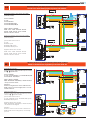
Impianti residenziali
Multi-block systems
Gli impianti residenziali si utilizzano per realizzare
impianti solitamente complessi dove molte unità
abitative, residenziali e/o villette (blocchi), ciascu-
no con propri ingressi e con un proprio sistema,
condividono anche degli ingressi principali co-
muni. Questi sistemi si realizzano utilizzando tre
tipologie diverse:
3. configurazione residenziale con blocchi X1 (solo
un VA/08) denominato XIP blk X1.
4. configurazione residenziale con blocchi XIP
(molti VA/08 ed ETI/XIP più ETI/SER e PCS/Porter)
denominato XIP blk XIP o XIP/LAN.
5. configurazione residenziale con blocchi XIP
(molti VA/08 ed ETI/XIP più ETI/SER e PCS/Porter) e
sottoblocchi X1 denominato XIP blk XIP/X1.
The multi-block systems are used to design com-
plex installation with a high number of units,
residential and/or villa (blocks), where each one of
those has its own entry panels and system; there-
fore all those could share the same main entry pan-
els and/or porters. These systems can be realized in
three different topologies:
1. Multi-block video entry system with X1 blocks
(only one VA/08) called XIP blk X1
2. Multi-block video entry system with XIP blocks
(more than one VA/08, ETI/XIP and in case ETI/SER
XIP and PCS/PORTER) called XIP blk XIP or XIP/LAN
3. Multi-block video entry system with XIP blocks
(more than one VA/08, ETI/XIP and in case ETI/SER
XIP and PCS/PORTER) and X1 sub block called XIP
blk XIP/X1.
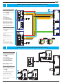
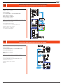
1. impianto monoblocco X1
1. X1 single block video entry system
3. Impianto residenziale con blocchi X1 (XIP blk X1)
3. Multi-block video entry system with X1 blocks (XIP blk X1)
2. impianto monoblocco XIP
2. XIP single block video entry system

6
4. Impianto residenziale con blocchi XIP (XIP blk XIP)
4. Multi-block video entry system with XIP blocks (XIP blk XIP)
5. Impianto residenziale con blocchi XIP e sottoblocchi X1 (XIP blk XIP/X1)
5. Multi-block video entry system with XIP blocks and X1 sub block (XIP blk XIP/X1)

7
Verifiche ed avvertenze
Riportiamo alcune avvertenze e alcune verifiche da effettuare prima della pro-
grammazione per ricercare e prevenire eventuali guasti nel sistema.
• anche se tutte le apparecchiature connesse sono protette contro eventuali
cortocircuiti, si raccomanda di togliere tensione prima di effettuare qual-
siasi operazione sui collegamenti.
• I collegamenti delle linee audio, video, dati e bus X1 devono essere effet-
tuati con doppini twistati possibilmente di tipo UTP5. La twistatura deve
essere eseguita fino in prossimità della morsettiera delle apparecchiature.
• Nel caso di cavi twistati multipli accertarsi che i collegamenti dei singoli con-
duttori twistati non vengano effettuati accoppiando 2 coppie di cavi( )
ma solo utilizzando i due poli del singolo cavo twistato .
• I collegamenti di alimentazione delle apparecchiature (posto esterno, de-
rivato interno,..) devono essere di tipo unipolare e di sezione adeguata al
carico ed alle distanze.
• I segnali delle linee audio, video si riferiscono tutte a massa (-). Si consiglia
di verificare il corretto collegamento a massa e l’opportuna sezione dei cavi
di alimentazione soprattutto in presenza di distanze superiori ai 150m tra
VA/08 ed i posti esterni.
In un impianto Xip (con VA/08) le linee polarizzate (+ e -) sono solo l’alimen-
tazione (+18Vdc), la linea video dei posti esterni Xip e/o la linea dati CAN.
Le linee non polarizzate sono l’audio e tutti i dispositivi collegati alla linea
X1.
Checks and warnings
The following are some warnings and checks to be performed prior to pro-
gramming to identify and prevent any possible defects in the system.
• even if all the units connected are protected from short circuits , it is sug-
gested to disconnect the mains before carrying out any operation on the
connections.
• The connections of the audio, video, data and X1 bus lines must be made
with twisted pairs, if possible UTP5 type. Twisting must be performed near
the terminal block of the units.
• If there are multiple twisted cables, make sure that the single twisted
conductors are not made by coupling two pairs of cables( ) but only by
using the two poles of the single twisted cable .
• The power supply connections of the units (entry panel, receiver,
and so forth) must be unipolar and of a suitable section for load
and distances.
• Signals of the audio, video lines all refer to earth (-). It is advisable to check
for proper earth connection and for suitable power supply cable sections,
especially when dealing with distances greater than 150m between VA/08
and entry panels.
In an Xip (with VA/08) the polarized lines (+ and -) are only the power sup-
ply (+18Vdc), the video line of the Xip entry panels and CAN data line.
The non-polarized lines are the audio, and all devices connected to the X1
line.

8
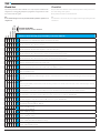
Check-list
La presente procedura è stata realizzata con lo scopo di poter analizzare tutti i
collegamenti e i settaggi degli impianti. Vi preghiamo di seguire tutte le verifi-
che come descritto di seguito.
N.B.:
Si raccomanda di togliere tensione prima di effettuare qualsiasi operazione sui
collegamenti.
Checklist
This procedure was realized in order to make it possible to analyse all connec-
tions and settings of the systems.
Please perform all checks as described below.
N.B.:
It is advisable to disconnect the power supply before doing anything with the
connections.
X1
Xip
Xip blx X1
Xip blx Xip (LAN)
Xip blx Xip (LAN)/X1
Sistemi verificabili
Systems which can be checked
Verifiche da fare con apparecchiature NON alimentate a 230Vca
Checks to be made with equipment NOT powered at 230V AC.
AVerificare che non ci sia l’alimentazione 230Vca collegata a nessun dispositivo.
Check that there is no 230V AC power supply connected to any device.
B1 Linea CAN (morsetti +D–): verificare l’impedenza della linea.
CAN bus (terminals +D–): check line impedance.
B2 Linea CAN (morsetti +D–): Verificare l’impedenza delle 2 linee CAN (+D–)
CAN bus (terminals +D–): Check the impedance of the 2 bus lines (+D–)
B3 Linea CAN (morsetti +D–): verificare l’assenza di corto circuiti verso massa o positivo.
CAN bus (terminals +D–): check for absence of short circuits towards earth or positive.
B4 Linea CAN (morsetti +D–): verificare l’assenza di corto circuiti verso massa o positivo.
CAN line (terminals +D–): check for absence of short circuits towards earth or positive.
C1 Linea Video: verificare l’impedenza della linea verso massa.
Video line: check impedance of the line towards earth.
C2 Linea Video: verificare l’impedenza della linea verso massa degli XDV/303 – VA/08.
Video line: check impedance of the line towards earth of the XDV/303 – VA/08.
C3 Linea Video: controllo ETI/XIP.
Video Line: ETI/XIP control.
D1
Linea audio: misura possibile inserendo una resistenza di valore conosciuto a fine linea e misurando il valore all’inizio della linea.
Audio line: measurement possible inserting a resistance of a known value at the end of a line and measuring its value at the beginning
of the line.
D2
Linea audio (con ETI/XIP): misura possibile inserendo una resistenza di valore conosciuto a fine linea e misurando il valore all’inizio della
linea.
Audio line (with ETI/XIP): measurement possible inserting a resistance of a known value at the end of a line and measuring its value at
the start of the line.
EVerificare l’impedenza della linea X1 (morsetti BB) collegata al VA/08 e alla targha X1 dal derivato più distante.
Check impedance of the X1 line (terminals BB) connected to the VA/08 and to the X1 from the most distant extension.
F1 Verificare l’impedenza della linea X1 (morsetti BB) collegata al selettore intercom VSE/301: NON POSSIBILE.
Check impedance of the X2 line (terminals BB) connected to intercom selector VSE/301: NOT POSSIBLE.
F2 Verificare l’impedenza della linea X1 (morsetti BB) in impianto semplice X1: NON POSSIBILE.
Check the impedance of the X1 line (terminals BB) in X1 basic system: NOT POSSIBLE.
G1 Controllo settaggi e cablaggi DC/08 – DVC/08.
Check settings and wiring DC/08 – DVC/08.
G2 Controllo settaggi monitor.
Control of monitor settings.
G3 Controllo settaggi XDV/303.
Control of XDV/303 settings.
G4 Controllo settaggi XDV/304.
Control of XDV/304 settings.
G5 Controllo settaggi XDV/304A, XDV/304, XDV/300A.
Control of XDV/304A, XDV/304, XDV/300A settings.
HControllo cablaggi tra VA/08, ETI/Xip.
Control of VA/08, ETI/Xip settings.

9
X1
Xip
Xip blx X1
Xip blx Xip (LAN)
Xip blx Xip (LAN)/X1
Sistemi verificabili
Systems which can be checked
Verifiche da fare con apparecchiature NON alimentate a 230Vca
Checks to be made with equipment NOT powered at 230V AC.
L1 Alimentare tutti i dispositivi.
Provide power to all devices.
L2 Verifica alimentazione dispositivi.
Check power supply the devices.
M1 Linea CAN: verificare tensione della linea rispetto a massa.
CAN line: check line voltage with respect to earth.
M2 Linea CAN: verificare tensione della linea rispetto a massa.
CAN line: check line voltage with respect to earth.
N1 Verifica alimentazione dispositivi X1 collegati ad alimentazione locale.
Check power supply to X1 devices connected to local power supplier.
N2 Verifica alimentazione dispositivi X1 collegati ai blocchi X1.
Check power supply of X1 devices connected to X1 blocks.
N3 Verifica alimentazione e collegamento della massa tra tutte le targhe X1.
Check power supply and connection of earth between all X1 entry plates X1.
N4 Verifica alimentazione VSE/301.
Check VSE/301 power supply.
N5 Verifica alimentazione linea X1 (morsetti BB) collegata al VA/08.
Check power supply of X1 line (terminals BB) connected to the VA/08.
N6 Verifica alimentazione linea X1 (morsetti BB) collegata alla targa X1.
Check power supply to X1 line (terminals BB) connected to entry panel X1.
N7 Verifica alimentazione linea X1 (morsetti BB) collegata al VSE/301.
Check power supply to X1 line (terminals BB) connected to the VSE/301.
Segnali verificabili nel sistema
Signals which can be checked in the system
O1 Segnale X1: dettaglio segnale ASK.
Signal X1: ASK signal detail.
O2 Segnale teorico CAN bus.
CAN bus theoretical signal.
O3 Segnale misurato su CAN bus da oscilloscopio.
CAN bus signal from oscilloscope.
O4 Segnale teorico linea video.
Video line theoretical signal.
O5 Segnale teorico linea audio.
Audio line theoretical signal.
O6 Verifica integrità driver CAN bus.
CAN bus driver integrity check.

10
AVerifiche da fare con apparecchiature NON alimentate a 230Vca
Checks to be made with equipment NOT powered at 230V AC.
Verificare che non ci sia l’ali-
mentazione 230Vca collegata a
nessun dispositivo.
Sistemi verificabili:
X1
XIP
Sistema XIP blk X1
Sistema XIP blk XIP (LAN)
Sistema XIP blk XIP(LAN)/X1
Apparecchiature verificabili:
AS/200(*)
VAS/100
VAS/101(*)
VAS/102(*)
VA/08
VA/01
XAS/301(*)
* non presenti nello schema
Check that there is no 230V AC
power supply connected to any
device.
Systems which can be checked:
X1
XIP
XIP blk X1 System
XIP blk XIP (LAN) System
XIP blk XIP(LAN)/X1 System
Equipment which can be che-
cked:
AS/200(*)
VAS/100
VAS/101(*)
VAS/102(*)
VA/08
VA/01
XAS/301(*)
* not included in the diagram
SYSTEM OFF
SYSTEM OFF
SYSTEM OFF
SYSTEM OFF

11
B1 Verifiche da fare con apparecchiature NON alimentate a 230Vca
Checks to be made with equipment NOT powered at 230V AC.
Linea CAN (morsetti +D–):
verificare l’impedenza della
linea da 82 a 110 .
Sistemi verificabili:
X1 – XIP
Sistema XIP blk X1
Sistema XIP blk XIP (LAN)
Sistema XIP blk XIP(LAN)/X1
Apparecchiature verificabili:
DDVC/08 VR – DDC/08 VR(*)
DVC/08 – DC/08(*) – VA/08
* non presenti nello schema
CAN bus (terminals +D–):
check line impedance
from 82 to 110 .
Systems which can be checked:
X1 – XIP
XIP blk X1 System
XIP blk XIP (LAN) System
XIP blk XIP(LAN)/X1 System
Equipment which can be che-
cked:
DDVC/08 VR – DDC/08 VR(*)
DVC/08 – DC/08(*) – VA/08
* not included in the diagram
B2 Verifiche da fare con apparecchiature NON alimentate a 230Vca
Checks to be made with equipment NOT powered at 230V AC.
Linea CAN (morsetti +D–):
verificare l’impedenza delle due
linee, da 82 a 110 .
Sistemi verificabili:
X1 – XIP
Sistema XIP blk X1
Sistema XIP blk XIP (LAN)
Sistema XIP blk XIP(LAN)/X1
Apparecchiature verificabili:
VA/08 – RIR/08
NOTA. I valori indicati si riferiscono
all’esempio di figura con distanza
alimentatore-targa di 250 m. Per si-
stemi con differente numero di posti
esterni contattare il servizio tecnico
Came.
CAN bus(terminals +D–):
check the impedance of the two bus
lines, from 82 to 110 .
Systems which can be checked:
X1 – XIP
XIP blk X1 System
XIP blk XIP (LAN) System
XIP blk XIP(LAN)/X1 System
Equipment which can be checked:
VA/08 – RIR/08
NOTE. The values refer to the exam-
ple of figure with power to plate dis-
tance of 250 m. For systems with dif-
ferent number of entry panels please
contact the Came technical service.
D
82÷110 Ω
Nota. I valori indicati si riferiscono all’esempio di figura con distanza alimenta-
tore-targa di 250 m. Per sistemi con differente numero di posti eterni contatta-
re il servizio Came
NOTE. The values refer to the example of figure with power to plate distance
of 250 m. For systems with different number of entry panels please contact the
Came technical service.
D
82÷110 Ω

12
B3 Verifiche da fare con apparecchiature NON alimentate a 230Vca
Checks to be made with equipment NOT powered at 230V AC.
Linea CAN (morsetti +D–):
Verificare l’assenza di corto
circuiti verso massa o positivo
(Test - 2 - 3 - 4).
Sistemi verificabili:
X1 – XIP
Sistema XIP blk X1
Sistema XIP blk XIP (LAN)
Sistema XIP blk XIP(LAN)/X1
Apparecchiature verificabili:
DDVC/08 VR – DDC/08 VR(*)
DVC/08 – DC/08(*) – VA/08
*non presenti nello schema
CAN bus (terminals +D–):
Check for absence of short cir-
cuits towards earth or positive
(Test - 2 - 3 - 4).
Systems which can be checked:
X1 – XIP
XIP blk X1 System
XIP blk XIP (LAN) System
XIP blk XIP(LAN)/X1 System
Equipment which can be che-
cked:
DDVC/08 VR – DDC/08 VR(*)
DVC/08 – DC/08(*) – VA/08
* not included in the diagram
B4 Verifiche da fare con apparecchiature NON alimentate a 230Vca
Checks to be made with equipment NOT powered at 230V AC.
Linea CAN (morsetti +D–):
Verificare l’assenza di corto
circuiti verso massa o positivo
(Test - 2 - 3 - 4).
Sistemi verificabili:
X1 – XIP
Sistema XIP blk X1
Sistema XIP blk XIP (LAN)
Sistema XIP blk XIP(LAN)/X1
Apparecchiature verificabili:
VA/08 – RIR/08
CAN bus (terminals +D–):
Check for absence of short cir-
cuits towards earth or positive
(Test - 2 - 3 - 4).
Systems which can be checked:
X1 – XIP
XIP blk X1 System
XIP blk XIP (LAN) System
XIP blk XIP(LAN)/X1 System
Equipment which can be che-
cked:
VA/08 – RIR/08
3
3
2
2
4
4

13
ETI-XIP
ETI-XIP
ETI-XIP
ETI-XIP
C1 Verifiche da fare con apparecchiature NON alimentate a 230Vca
Checks to be made with equipment NOT powered at 230V AC.
C2 Verifiche da fare con apparecchiature NON alimentate a 230Vca
Checks to be made with equipment NOT powered at 230V AC.
Linea Video:
Verificare l’impedenza della
linea verso massa, da 56 a 81
Ohm (Test - 2).
Sistemi verificabili:
X1 – XIP
Sistema XIP blk X1
Sistema XIP blk XIP (LAN)
Sistema XIP blk XIP(LAN)/X1
Apparecchiature verificabili:
DDVC/08 VR – DDC/08 VR(*)
DVC/08 – DC/08(*) – VA/08
* non presenti nello schema
Video Line:
Check the impedance of the line
towards earth, from 56 to 81
(Test - 2).
Systems which can be checked:
X1 – XIP
XIP blk X1 System
XIP blk XIP (LAN) System
XIP blk XIP(LAN)/X1 System
Equipment which can be che-
cked:
DDVC/08 VR – DDC/08 VR(*)
DVC/08 – DC/08(*) – VA/08
* not included in the diagram
Linea Video (con XDV/303):
Verificare l’impedenza della linea
verso massa, da 56 a 81 Ohm
(Test - 2).
Sistemi verificabili:
X1 – XIP – Sistema XIP blk X1
Sistema XIP blk XIP (LAN)
Sistema XIP blk XIP(LAN)/X1
Apparecchiature verificabili:
XDV/303 – VA/08
Video Line (with XDV/303):
Check the impedance of the line
towards earth, from 56 to 81
(Test - 2).
Systems which can be checked:
X1 – XIP – XIP blk X1 System
XIP blk XIP (LAN) System
XIP blk XIP(LAN)/X1 System
Equipment which can be checked:
XDV/303 – VA/08
ETI-XIP
ETI-XIP
56÷81 Ω 56÷81 Ω
2
56÷81 Ω 56÷81 Ω
2

14
C3 Verifiche da fare con apparecchiature NON alimentate a 230Vca
Checks to be made with equipment NOT powered at 230V AC.
D1 Verifiche da fare con apparecchiature NON alimentate a 230Vca
Checks to be made with equipment NOT powered at 230V AC.
Linea Video (con ETI/Xip):
Verificare l’impedenza della
linea verso massa, da 28 a 37
Ohm (Test - 2).
Sistemi verificabili:
X1 – XIP – Sistema XIP blk X1
Sistema XIP blk XIP (LAN)
Sistema XIP blk XIP(LAN)/X1
Apparecchiature verificabili:
XDV/303 – ETI/XIP – VA/08
Video Line (with ETI/Xip):
Check the impedance of the
line towards earth, from 28 to
37 (Test - 2).
Systems which can be checked:
X1 – XIP – XIP blk X1 System
XIP blk XIP (LAN) System
XIP blk XIP(LAN)/X1 System
Equipment which can be
checked:
XDV/303 – ETI/XIP – VA/08
ETI-XIP
ETI-XIP
28÷37 Ω 28÷37 Ω
2
Linea audio:
nessuna misura possibile.
Eventualmente inserire una re-
sistenza di valore conosciuto (R)
a fine linea e misurarne il valore
all’inizio della linea per verifica-
re la continuità. Il valore sarà R
o R+40.
Sistemi verificabili:
X1 – XIP – Sistema XIP blk X1
Sistema XIP blk XIP (LAN)
Sistema XIP blk XIP(LAN)/X1
Apparecchiature verificabili:
DDVC/08 VR – DDC/08 VR(*)
DVC/08 – DC/08(*) – VA/08
* non presenti nello schema
Audio line:
no measurement possible.
You may try inserting a resist-
ance of a known value (R) at the
end of a line and measure its
value at the start of the line to
check continuity. Figure will be R
or R+40 .
Systems which can be checked:
X1 – XIP – XIP blk X1 System
XIP blk XIP (LAN) System
XIP blk XIP(LAN)/X1 System
Equipment which can be
checked:
DDVC/08 VR – DDC/08 VR(*)
DVC/08 – DC/08(*) – VA/08
* not included in the diagram
R÷R+40 Ω
RΩ
NO TEST!

15
D2 Verifiche da fare con apparecchiature NON alimentate a 230Vca
Checks to be made with equipment NOT powered at 230V AC.
E Verifiche da fare con apparecchiature NON alimentate a 230Vca
Checks to be made with equipment NOT powered at 230V AC.
Linea audio (con ETI/Xip):
nessuna misura possibile.
Eventualmente inserire una resistenza
di valore conosciuto (R) a fine linea
e misurarne il valore all’inizio della
linea per verificare la continuità. Il
valore sarà R o R+40.
Sistemi verificabili:
X1 – XIP – Sistema XIP blk X1
Sistema XIP blk XIP (LAN)
Sistema XIP blk XIP(LAN)/X1
Apparecchiature verificabili:
DDVC/08 VR(*) – DDC/08 VR(*)
DVC/08 – DC/08(*) – VA/08(*)
ETI/XIP
* non presenti nello schema
Audio line (with ETI/Xip):
no measurement possible.
You may try inserting a resistance
of a known value (R) at the end of
a line and measure its value at the
start of the line to check continuity.
Figure will be R or R+40 .
Systems which can be checked:
X1 – XIP – XIP blk X1 System
XIP blk XIP (LAN) System
XIP blk XIP(LAN)/X1 System
Equipment which can be checked:
DDVC/08 VR(*) – DDC/08 VR(*)
DVC/08 – DC/08(*) – VA/08(*)
ETI/XIP
* not included in the diagram
ETI-XIP
ETI-XIP
Linea X1 (morsetti BB):
verificare l’impedenza della
linea da 1100 a 1500 .
Sistemi verificabili:
X1 – XIP – Sistema XIP blk X1
Sistema XIP blk XIP (LAN)
Sistema XIP blk XIP(LAN)/X1
Apparecchiature verificabili:
VA/01 – VA/08
X1 line (terminals BB):
Check the impedance of the line
from 1100 to 1500 .
Systems which can be checked:
X1 – XIP – XIP blk X1 System
XIP blk XIP (LAN) System
XIP blk XIP(LAN)/X1 System
Equipment which can be
checked:
VA/01 – VA/08
RΩ
R÷R+40 Ω
B
1100÷1500 Ω

16
F1 Verifiche da fare con apparecchiature NON alimentate a 230Vca
Checks to be made with equipment NOT powered at 230V AC.
F2 Verifiche da fare con apparecchiature NON alimentate a 230Vca
Checks to be made with equipment NOT powered at 230V AC.
Linea X1 (morsetti BB):
verificare l’impedenza della linea
collegata al selettore intercom
VSE/301 (1100 ÷1500 ).
Sistemi verificabili:
X1 – XIP – Sistema XIP blk X1
Sistema XIP blk XIP (LAN)
Sistema XIP blk XIP(LAN)/X1
Apparecchiature verificabili:
VSE/301
Verificare l’impedenza della linea X1
(morsetti BB) in impianto semplice
X1: NON POSSIBILE.
Sistemi verificabili:
X1
Apparecchiature verificabili:
DVC/01 – DC/01(*)
*non presenti nello schema
X2 line (terminals BB):
check impedance of the line con-
nected to the VSE/301 intercom
selector (1100 ÷1500 ).
Systems which can be checked:
X1 – XIP – XIP blk X1 System
XIP blk XIP (LAN) System
XIP blk XIP(LAN)/X1 System
Equipment which can be checked:
VSE/301
Check the impedance of the X2 line
(terminals BB) in X2 basic system:
NOT POSSIBLE.
Systems which can be checked:
X1
Equipment which can be checked:
DVC/01 – DC/01(*)
* not included in the diagram
NO TEST!
1100÷1500 Ω

17
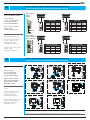
G1 Verifiche da fare con apparecchiature NON alimentate a 230Vca
Checks to be made with equipment NOT powered at 230V AC.
G2 Verifiche da fare con apparecchiature NON alimentate a 230Vca
Checks to be made with equipment NOT powered at 230V AC.
Controllo settaggi e cablaggi Targhe
XIP tipo THANGRAM e DIGITHA.
Sistemi verificabili:
X1 – XIP – Sistema XIP blk X1
Sistema XIP blk XIP (LAN)
Sistema XIP blk XIP(LAN)/X1
Apparecchiature verificabili:
DVC/08 – DC/08
DDVC/08 VR – DDC/08 VR
Check of Xip entry panel
THANGRAM and DIGITAL type.
Systems which can be checked:
X1 – XIP – XIP blk X1 System
XIP blk XIP (LAN) System
XIP blk XIP(LAN)/X1 System
Equipment which can be checked:
DVC/08 – DC/08
DDVC/08 VR – DDC/08 VR
Controllo settaggi e cablaggi deri-
vati.
Sistemi verificabili:
XIP – Sistema XIP blk X1
Sistema XIP blk XIP (LAN)
Sistema XIP blk XIP(LAN)/X1
Apparecchiature verificabili:
NOVA – LINEA – LINEA BASIC
OPHERA – MITHO – OPALE
OPALEWIDE – PERLA
Control of extension settings and
wiring.
Systems which can be checked:
X1 – XIP – XIP blk X1 System
XIP blk XIP (LAN) System
XIP blk XIP(LAN)/X1 System
Equipment which can be checked:
NOVA – LINEA – LINEA BASIC
OPHERA – MITHO – OPALE
OPALEWIDE – PERLA
1
ON
24
3
CN4
MINI USB
SW2
DDVC/08 VR
SW2
L1<200 m
(Default)
L1>200 m
L1<500 m L1>500 m
1OFF OFF ON
2OFF OFF ON
3OFF ON ON
4OFF OFF OFF
DVC/08 - DVC/08 ME
SW2
L1<200 m
(Default)
L1>200 m
L1<500 m L1>500 m
1OFF OFF ON
2OFF OFF ON
3OFF ON ON
DDC/08 VR
SW2
L2<200 m
(Default)
L2>200 m
L2<500 m L2>500 m
1OFF OFF ON
2OFF OFF ON
3OFF OFF OFF
4OFF OFF OFF
DC/08 - DC/08 ME
SW2
L2<200 m
(Default)
L2>200 m
L2<500 m L2>500 m
1OFF OFF ON
2OFF OFF ON
3OFF OFF OFF
Selettore SW2 su
DDC/08
DDVC/08
Selettore SW2 su
DVC/08 - DVC/08 ME
DC/08 - DC/08 ME
VA/08
VA/08
L1
VA/08
VA/08
L2
M4M1
M2M5 M3
+12V
+D – +V1– +V2–
A A +D – +V3– +V4–
A A
M1
CN1
CN4
M2
CN2
A
A
D
V
PROG
DATI
1 2
ON
3
(*)
IN
OUT
MINI USB
VLS/101
L
N
SW2
VA/08
VA/08
L1
VA/08 VA/08
VA/08
VA/08
L2
VA/08 VA/08
OPL
CL.RES.
B
M1
AL
BusLocal
M/S/K
OPLW
CL.RES.
B
M1
AL
OPL
CL.RES.
B
M1
AL
BusLocal
M/S/K
OPLW
CL.RES.
B
M1
AL
OPL
CL.RES.
B
M1
AL
BusLocal
M/S/K
OPLW
CL.RES.
B
M1
AL
B
M1
AL
M/S CL.RES
OPLW
PERLA
CL.RES.
B
M1
AL
OPL
CL.RES.
B
M1
AL
BusLocal
M/S/K
B
M1
AL
M/S CL.RES
OPLW
PERLA
CL.RES.
B
M1
AL
OPL
CL.RES.
B
M1
AL
BusLocal
M/S/K
B
M1
AL
M/S CL.RES
OPLW
PERLA
CL.RES.
B
M1
AL
OPL
CL.RES.
B
M1
AL
BusLocal
M/S/K
Verificare il collegamento dei cablaggi evidenziati e la posizione dei ponticelli secondo lo schema in uso.
Check the connection of the highlighted wiring and the position of the jumpers according to the diagram in use.

18
G3 Verifiche da fare con apparecchiature NON alimentate a 230Vca
Checks to be made with equipment NOT powered at 230V AC.
G4 Verifiche da fare con apparecchiature NON alimentate a 230Vca
Checks to be made with equipment NOT powered at 230V AC.
Controllo settaggi XDV/303.
Sistemi verificabili:
X1 – XIP – Sistema XIP blk X1
Sistema XIP blk XIP (LAN)
Sistema XIP blk XIP(LAN)/X1
Apparecchiature verificabili:
XDV/303
Control of XDV/303 setting.
Systems which can be checked:
X1 – XIP – XIP blk X1 System
XIP blk XIP (LAN) System
XIP blk XIP(LAN)/X1 System
Equipment which can be checked:
XDV/303
Controllo settaggi distributori video
XDV/304.
Sistemi verificabili:
X1 – XIP – Sistema XIP blk X1
Sistema XIP blk XIP (LAN)
Sistema XIP blk XIP(LAN)/X1
Apparecchiature verificabili:
XDV/304
Control of XDV/304 video distributor
settings.
Systems which can be checked:
X1 – XIP – XIP blk X1 System
XIP blk XIP (LAN) System
XIP blk XIP(LAN)/X1 System
Equipment which can be checked:
XDV/304
ETI-XIP
ETI-XIP
Attenzione:
L’impostazione dei ponticelli è sempre necessaria! Riferirsi alla tabella riportata nelle
relative istruzioni.
Verificare che le uscite non utilizzate (V1-V2-V3-V4-V4R) siano sempre chiuse con due
resistenze da 56 a massa (vedi V4R nello schema).
Attention:
Setting of the jumpers is always necessary! Refer to the table included in the relative
instructions.
Check that unused outputs (V1-V2-V3-V4-V4R) are always closed with two 56 Ohm
resistances at earth ( see V4R in the diagram).
Attenzione:
• Se una uscita del distributore
non viene utilizzata oppure viene
utilizzata per un citofono chiudere il
relativo ponticello.
• L’uscita 1 non ha il ponticello di
chiusura. Se non utilizzata collegare
una resistenza (100-Ohm) in serie ad
un condensatore (470-pF).
• Chiudere l’uscita se si collega solo
una cornetta senza il monitor.
• Chiudere SW0 se la linea montante
non prosegue.
Attention:
• If an output of the distributor is not
used or it is used for an audio receiver,
close the relative jumper.
• Output 1 does not have a closure
jumper. If not used, connect a
resistance (100-Ohm) in series to a
capacitor (470-pF).
• Close the output if only one receiver is
connected without a monitor.
• Close SW0 if the busbar connection
line does not continue.
JUMPERS
JUMPERS
INGRESSI/USCITE VIDEO
VIDEO INPUT/OUTPUT
SW3 SW4 SW5 V1 V2 V3 V4 V4R DESCRIZIONE / DESCRIPTION
OFF ON OFF IN IN IN OUT (*) Selettore con 3 ingressi e 1 uscita.
Selector with 3 inputs and 1 output.
(*) Uscita V4 commutata da utilizzare per collegare più XDV/303 in parallelo.
(*) Switched V4 output to use when connecting a number of XDV/303 units in parallel.
Compensazione segnale video – Video signal compensation
SW1
OFF < 50 m (condizione predefinita).
< 50 m (factory setting).
100m Compensa la linea da 50 a 150 m.
Compensates line in range 50 to 150 m.
200m Compensa la linea da 150 a 250 m.
Compensates line in range 150 to 250 m.
SW2
OFF
Condizione predefinita; da utilizzare per applicazioni particolari.
Factory setting; use for special applications.
SW6
OFF < 50 m (condizione predefinita).
< 50 m (factory setting).
ON Compensa la linea in uscita V4R fino a 150 m.
Compensates V4R OUT line up to 150 m.

19
G5 Verifiche da fare con apparecchiature NON alimentate a 230Vca
Checks to be made with equipment NOT powered at 230V AC.
H Verifiche da fare con apparecchiature NON alimentate a 230Vca
Checks to be made with equipment NOT powered at 230V AC.
Controllo settaggi:
XDV/304A, XDV/300A.
Sistemi verificabili:
X1 – XIP – Sistema XIP blk X1
Sistema XIP blk XIP (LAN)
Sistema XIP blk XIP(LAN)/X1
Apparecchiature verificabili:
XDV/300A – XDV/304 – XDV/304A
Control of setting:
XDV/304A, XDV/300A.
Systems which can be checked:
X1 – XIP – XIP blk X1 System
XIP blk XIP (LAN) System
XIP blk XIP(LAN)/X1 System
Equipment which can be checked:
XDV/300A – XDV/304 – XDV/304A
Controllo cablaggi tra
VA/08 e ETI/XIP.
Sistemi verificabili:
X1 – XIP – Sistema XIP blk X1
Sistema XIP blk XIP (LAN)
Sistema XIP blk XIP(LAN)/X1
Apparecchiature verificabili:
VA/08 – ETI/Xip
Control of wiring between VA/08
and ETI/XIP.
Systems which can be checked:
X1 – XIP – XIP blk X1 System
XIP blk XIP (LAN) System
XIP blk XIP(LAN)/X1 System
Equipment which can be checked:
VA/08 – ETI/Xip
Attenzione!
XDV/300A: impostare a 20dB se collegato su una uscita (1, 2, 3, 4) di un XDV/304. Impostare a 6dB se collegato lungo la
dorsale.
XDV/304A: chiudere le uscite (B1,B2,B3,B4) con il ponticello relativo se non utilizzate o se collegato ad un citofono.
Chiudere B OUT tramite SW5 se la linea montante non prosegue.
Attention!
XDV/300A: set at 20dB if connected to an output (1, 2, 3, 4) of a XDV/304. Set at 6dB if connected along the ridge.
XDV/304A: close the outputs (B1,B2,B3,B4) with the relative jumper if not used or if connected to a receiver. Close B OUT
by means of SW5 if the busbar connection line does not continue.
Se le linee video (2, 3, 4, OUT) non vengono collegate, chiude-
re il DIPSWITCH corrispondente.
If the video lines (2, 3, 4, OUT) aren’t connected close the
pertinent DIPSWITCH.
Se le linee video (B2, B3, B4, OUT) non vengono collegate,
chiudere il DIP-SWITCH corrispondente.
If the video lines (B2, B3, B4, OUT) aren’t connected close the
pertinent DIP-SWITCH.
XDV/300A
OUT
IN
x 16
60 x 44
2WS
1WS
6 dB
20 dB
XDV/304
OUT
4
3
SW4
2
1
IN
SW3
SWO
SW2
x 16
60 x 44
B4
M2
B3
XDV/304A
B2
B1
SW3
B OUT
B IN
SW2
SW5
SW1
SW4
6 DIN
M1
M3
XDV/300A
OUT
IN
x 16
60 x 44
2WS
1WS
6 dB
20 dB
XDV/304
OUT
4
3
SW4
2
1
IN
SW3
SWO
SW2
x 16
60 x 44
B4
M2
B3
XDV/304A
B2
B1
SW3
B OUT
B IN
SW2
SW5
SW1
SW4
6 DIN
M1
M3
ETI-XIP

20
L1 Verifiche da fare con apparecchiature alimentate a 230Vca
Checks to be made with equipment powered at 230V AC.
Verificare che ci sia l’alimenta-
zione 230Vca collegata ai dispo-
sitivi che lo richiedono.
Sistemi verificabili:
X1
XIP
Sistema XIP blk X1
Sistema XIP blk XIP (LAN)
Sistema XIP blk XIP(LAN)/X1
Apparecchiature verificabili:
AS/200(*)
VAS/100
VAS/101(*)
VAS/102(*)
VA/08
VA/01
XAS/301(*)
* non presenti nello schema
Make sure there is 230V AC
power connected to the devices
that require it.
Systems which can be checked:
X1
XIP
XIP blk X1 System
XIP blk XIP (LAN) System
XIP blk XIP(LAN)/X1 System
Equipment which can be che-
cked:
AS/200(*)
VAS/100
VAS/101(*)
VAS/102(*)
VA/08
VA/01
XAS/301(*)
* not included in the diagram
SYSTEM ON
SYSTEM ON
SYSTEM ON
SYSTEM ON
La pagina si sta caricando...
La pagina si sta caricando...
La pagina si sta caricando...
La pagina si sta caricando...
La pagina si sta caricando...
La pagina si sta caricando...
La pagina si sta caricando...
La pagina si sta caricando...
La pagina si sta caricando...
La pagina si sta caricando...
-
 1
1
-
 2
2
-
 3
3
-
 4
4
-
 5
5
-
 6
6
-
 7
7
-
 8
8
-
 9
9
-
 10
10
-
 11
11
-
 12
12
-
 13
13
-
 14
14
-
 15
15
-
 16
16
-
 17
17
-
 18
18
-
 19
19
-
 20
20
-
 21
21
-
 22
22
-
 23
23
-
 24
24
-
 25
25
-
 26
26
-
 27
27
-
 28
28
-
 29
29
-
 30
30


CAME Troubleshooting XIP Guida d'installazione
- Tipo
- Guida d'installazione
in altre lingue
Documenti correlati
-
CAME ETI/XIP APP Guida d'installazione
-
-
-
-
-
-
CAME PEC IP Guida d'installazione
-
-