Pall "Novasip" Filter Assemblies Step-by-Step Guide
- Tipo
- Step-by-Step Guide

Assembly and Installation Procedures for
"
Novasip
"
Filter Assemblies for model numbers C****P1
USD1642a
Mode d'emploi et installation du filtre
"
Novasip
"
Référence du filtre C****P1
Montage- und Installationsanleitung für "Novasip"
Filtereinheiten für Artikelnummern C****P1
Procedimientos de montaje e instalación para
conjuntos filtrantes
"Novasip" modelos C****P1
Procedure di installazione e di impiego dei filtri
"Novasip" codice C****P1
Montering och installationsrutiner för
"Novasip"
Filter För modellnummer
C****P1
Japanese
Text Required

Assembly and Installation Procedures for
"
Novasip
"
Filter Assemblies for model numbers C****P1
3
The following procedures are required to install ‘Pall’ ‘Novasip’ disposable filter
assemblies and should be thoroughly read as they contain valuable information gained
by extensive experience. It is very important that all instructions are carefully followed
and where appropriate be incorporated into the operator’s standard operating
procedures. If some of the procedures do not suit your needs, please consult Pall or your
local distributor before finalising your system.
1. SPECIFICATIONS
Materials of construction
Filter shell: Polyetherimide
Other materials will depend on the type of Novasip filter selected. Refer to Pall
Publications USD1647 and USD1648 for further information.
For use in gases and liquids
Maximum working pressureat 40°C
in compatible fluids: 6.5 barg
Maximum differential pressure: Refer to appropriate Pall data sheet
Inlet/outlet: 1-inch/11/2-inch ‘Triclover’ compatible
Vent/drain;
Vent valve: ‘Stäubli’ connection to suit a RBE 03.1906 female
Stäubli socket
Drain valve: Hosebarb connection to suit flexible pipe with ID
between 5 and 7 mm
WARNING: NOVASIP FILTER ASSEMBLIES SHOULD NOT BE USED WITH FLUIDS
INCOMPATIBLE WITH THE MATERIALS OF CONSTRUCTION, INCLUDING
CLEANING AGENTS. INCOMPATIBLE MATERIALS ARE THOSE WHICH
CHEMICALLY ATTACK, SOFTEN, STRESS CRACK OR ADVERSELY AFFECT THE
MATERIALS OF CONSTRUCTION IN ANY WAY. USERS SHOULD CHECK THE
COMPATIBILITY OF PROCESS FLUIDS BEFORE USE.
It is the user’s responsibility to check actual operating conditions to ensure that the filter
assembly is compatible with the application and within local safety codes.

4
2. RECEIPT OF EQUIPMENT
(a) Store the filter assemblies in clean, dry conditions, out of direct sunlight,
and wherever practical in the packaging as delivered.
(b) DO NOT remove from its protective packaging until just before installation.
(c) Ensure that the type of the filter assembly selected is suitable for the
application. In addition to the part number each filter assembly is identified by an
unique identification batch/serial number.
IMPORTANT: NOVASIP FILTER ASSEMBLIES SHOULD BE INSPECTED FOR SIGNS
OF DAMAGE BEFORE USE. IF USED OVER EXTENDED TIME PERIODS, IT IS
RECOMMENDED THAT INSPECTION IS PERFORMED AT LEAST EVERY WEEK. IF
DAMAGE OR ANY OTHER POTENTIAL MALFUNCTION IS OBSERVED, THE FILTER
ASSEMBLY SHOULD BE REPLACED.
3. INSTALLATION AND OPERATION
3.1 Installation
Before installation it is essential to verify that the filter type selected is suitable for the gas
or liquid to be filtered and to follow the appropriate instructions listed below.
Important: In liquid and pressurised gas applications the filter assembly must be
installed with the process flow as indicated by the flow direction arrow on the
assembly.
(a) Install the filter assembly in line using appropriate connections.
(b) The filter assembly should be positioned in an attitude that allows effective venting
and draining of the filter to be carried out before and during operation.
(c) The filter assembly should be installed in an appropriate orientation allowing integrity
testing as required.
(d) Whereapositive pressureexists downstream of the filter, a sensitive check valve may
be needed to prevent back pressure damage due to reverse flow.
(e) Whereapulsating flow is present, the filter should be protected by a surge tank
upstream.
(f) Where a rapidly closing downstream valve is present, the possibility of pressure
pulsing and subsequent filter damage exists. The filter should be protected by a
surge tank between valve and filter.
(g) Side and end loads should be avoided during installation and use.
(h) Allowance should be made for expansion during sterilisation.

(i) Overtightening of the inlet and outlet Triclover clamps may result in damage of the
inlet and outlet Triclover connectors at steaming temperatures. It is recommended
that the clamps are fully tightened by hand, and then loosened by one turn. It is also
recommended that users verify that this provides a leak proof seal.
WARNING: NOVASIP FILTER ASSEMBLIES HAVE BEEN EXTENSIVELY VALIDATED
FOR USE IN PRESSURISED GAS SYSTEMS AND FOR STEAM STERILISATION IN
PLACE. USERS SHOULD TAKE THE APPROPRIATE PRECAUTIONS ASSOCIATED
WITH SUCH PRESSURISED AND HIGH TEMPERATURE SYSTEMS TO PROTECT
OPERATORS SUCH AS SAFETY GLASSES AND GLOVES. IN ADDITION PALL
RECOMMEND THE USE OF A PROTECTIVE SHIELD TO PROTECT OPERATORS
FROM LIVE STEAM IN THE EVENT OF A LEAK OR BREAKAGE.
3.2 Operation
On installation and prior to steaming verify the integrity of the assembly.
In liquid applications the filter assembly must be vented by opening the vent valve when
the filter is initially brought on stream. The vent valve should then be closed when liquid
issues from it.
4. INTEGRITY TESTING
Filter integrity should be verified beforeand after filtration by means of an appropriate
integrity test procedure. Depending on the filter type and grade, the Pall Forward Flow,
water intrusion and bubble point tests may be suitable.
4.1 Forward Flow Test
The Pall Forward Flow test can be performed on a sterile or non-sterile filter assembly.
The test is suitable for all types of Pall sterilising grade and other fine particulate grade
filters.
In summary the test requires establishment of a pre-determined test pressureusing
compressed air or nitrogen in the filter assembly, on the upstream side of the pre-wetted
filter membrane. Under the influence of this constant pressure, there is a flow of test gas
through the membrane resulting from diffusive and open pore flow. Pall has correlated
measurement of the volume of gas flow with the results of bacterial retention tests. The
validated integrity test enables filter performance capability to be determined in a
pharmaceutical process without the risk of contaminating the test system. Pall filter
validation guides carry moredetail for specific filter types.
The ‘Palltronic’ ‘Flowstar’ or ‘TruFlow’ test instruments carry out the Forward Flow test by
measurement of diffusive flow at constant pressure from the upstream side of the filter,
thereby eliminating the risk of contaminating the downstream (sterile) side of the filter.
The Palltronic instrument is connected to the filter assembly after wetting the filter with
an appropriate test liquid. After entering the necessary information and test parameters
the instrument will carry out the ForwardFlow test and report the result. During the test
temperature should not vary by more than ±1°C.
5

6
Appropriate wetting liquids for the Forward Flow test with Pall filters are as follows:
Filter Medium Type
Ultipor N66
N66 Posidyne
Fluorodyne II
Ultipor VFDV50
Emflon PFR
Wetting Liquids
Water, 60/40 (V/V) IPA*/water
Water, 60/40 (V/V) IPA*/water
Water, 60/40 (V/V) IPA*/water
30/70 (V/V) IPA*/water
60/40 (V/V) IPA*/water, 25/75 t-butyl alcohol water
*Isopropyl alchohol (IPA)
During process operation it is frequently more convenient to be able to test a filter whilst
wet with the actual process fluid. This is nearly always possible; Pall Scientific and
Laboratory Services should be contacted for further information.
4.2 Water Intrusion Test
The Pall Water Intrusion test can be performed on a sterile or non-sterile filter assembly.
The test is suitable for Pall ‘Emflon’ PFR hydrophobic sterilising grade gas filters.
If the upstream side of a dry hydrophobic filter assembly is filled with water and
pressurised, the hydrophobic nature of the porous membrane will prevent the bulk flow of
liquid through the filter until the intrusion pressure is reached. At pressures below the
intrusion pressureasmall but measurable flow of water through the membrane occurs.
The presence of larger pores in the filter will be detected by an increased flow resulting
from to bulk water flow through these pores. This principle forms the basis of the water
intrusion test. Pall has correlated measurement of water flow with the results of bacterial
retention tests, permitting the test to be used to determine filter performance capability.
Pall Scientific and Technical Reports carry more detailed information about this test.
The upstream side of the filter assembly is filled with distilled or deionised water at 20°C
± 2°C and of surface tension not less than 0.071 N/m. Under the influence of a pre-
determined applied pressure, there is a fall in water level in the filter assembly due to
factors such as pleat compression and passage of trapped air through the membrane.
After allowing an appropriate period for stabilisation, water flow is measured while
maintaining constant upstream pressure.
The Palltronic Flowstar or TruFlow test instruments carry out the water intrusion test by
measurement of flow from the upstream side of the filter, thereby eliminating the risk of
contaminating the downstream (sterile) side of the filter. The Palltronic instrument is
connected to the filter assembly after filling the filter assembly with water. After entering
the necessary information and test parameters the instrument will carry out the water
intrusion test and report the result. On completion of the test the filter assembly is
drained of water and, in many applications, the filter is now ready for use. A drying
procedurecan be used in those applications wherethe filter must be dry beforeuse.

4.3 Bubble Point Test
Abubble point type test can be performed on a sterile or non-sterile filter assembly. The
test can be applied to all types of Pall sterilising grade and other fine particulate grade
filters.
Aprogressively increasing pressure is applied using compressed air or nitrogen in the
filter assembly, on the upstream side of the pre-wetted filter membrane. A flow of gas
occurs through the membrane resulting from expulsion of the wetting liquid from the
largest filter pores.
The Palltronic Flowstar or TruFlow test instruments carry out a bubble point test from the
upstream side of the filter, thereby eliminating the risk of contaminating the downstream
(sterile) side of the filter. The Palltronic instrument is connected to the filter assembly after
wetting the filter with an appropriate test liquid. After entering the necessary information
and test parameters the instrument will carry out a bubble point test and report the
result.
Appropriate wetting liquids for a bubble point test with Pall filters are as follows:
7
During process operation it is frequently moreconvenient to be able to test a filter whilst
wet with the actual process fluid. This is nearly always possible; Pall Scientific and
Laboratory Services should be contacted for further information.
5. STERILISATION
THESE DISPOSABLE NOVASIP FILTER ASSEMBLIES MAY BE STEAM STERILISED IN
PLACE OR BY AUTOCLAVE
WARNING: DO NOT AUTOCLAVE FILTER ASSEMBLY IN THE BAG.
5.1 Novasip filter assemblies are supplied non-sterilised.
5.2 The Novasip filter assembly should only be steam sterilised or autoclaved as follows:
(a) Up to 142°C
(b) DO NOT steam sterilise at higher temperatures.
(c) For specific steam sterilisation limits please contact Pall.
(d) Quench cooling is not recommended
Filter Medium Type
Ultipor N66
N66 Posidyne
Fluorodyne II
Ultipor VF DV50
Emflon PFR
Wetting Liquids
Water,60/40 (V/V) IPA*/water
Water, 60/40 (V/V) IPA*/water
Water, 60/40 (V/V) IPA*/water
30/70 (V/V) IPA*/water
60/40 (V/V) IPA*/water, 25/75 t-butyl alcohol water

8
5.3 Detailed information on sterilisation of Pall filters is provided in Pall Publication
USD805j and a typical procedure for steam in place sterilisation of a dry filter is given
below. Further information can be obtained by contacting Pall.
5.4 For gas filter assemblies a numbered plastic ring is supplied, for fitting if required, this
can be used to record the number of steam sterilisation cycles carried out.
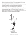
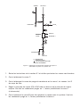
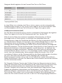
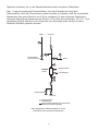
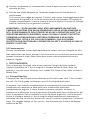
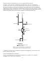
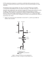
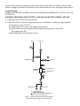
Typical Procedure for Steam in Place Sterilisation of a Dry Filter Assembly
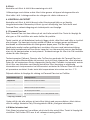
A recommended filter installation is presented in Figure 1. Pressure gauges which can be
read with accuracy over the range of 0-3 bar must be installed to monitor steam pressure
and differential pressure across the filter assembly during the sterilisation cycle. To
ensure effective sterilisation, steam pressure (measured at position T) in the assembly
should be held at a minimum of 121°C (1.1 bar g saturated steam) for the minimum time
validated by the user as necessary to achieve system sterilisation.
P
1
P
2
T
C
DRAIN D E
NOVASIP
FILTER
AIR/N
P
3
F
A
B
P
4
DRAIN I
2
VENT G
DRAIN J
PROCESS
PROCESS
STEAM
P=PRESSURE GAUGE
T=THERMOCOUPLE
THISPIPEWORK SHOULDBE
KEPT TOAMINIMUM
Figure 1. Recommended filter installation for steam in place
sterilisation of a dry filter assembly

9
1. Follow installations instructions in section 3.1 and ensure all valves are closed.
2. Fully open valve C.
3. Fully open condensate drain trap or valve I, housing drain valve J and housing vent
valve G.
4. Preset steam pressure (P4) to 300 mbar above the steam pressure required at the
filter assembly. After condensate has been expelled from I partially close valve I (if
necessary).
5. Slowly open steam valve B to admit steam to system. After condensate has been
expelled from J, partially close valve J.
6. Partially close vent valve G when steam flow is evident, ENSURING THAT
PRESSURE AT P2 REMAINS WITHIN 300 MBAR OF PRESSURE AT P1. Partially
open drain valve D to drain condensate.
7. Permit steam to flow through the system until steam pressure is stabilised, and
adjust the regulated steam supply until the validated temperature is achieved at
position T.Monitor temperature at T for the necessary sterilisation time.
ENSURE THAT PRESSURE AT P2 REMAINS WITHIN 300 MBAR OF PRESSURE AT
P1. IT IS RECOMMENDED THAT STEAM STERILISATION IS FOLLOWED BY AIR
BALLASTING AS DETAILED IN THE FOLLOWING SECTION.
8. Preset pressure (P3) of regulated air or N2 at 200 mbar above steam pressure (P4).
9. When sterilisation time is complete close drain valves D, J and I and vent valve G.
Close steam valve B and immediately introduce preregulated air or N2
through valve F.
10. To assist cooling steam may be flushed from the assembly by carefully opening vent
valve G and drain valve J. Close valves G and J after flushing.
11. Allow assembly to cool to ambient or to process fluid temperature.
12. Close air or nitrogen valve F.
13. Relieve the gas pressurein the filter assembly via vent valve G. Filter assembly is
now ready for use.
6. FILTER ASSEMBLYREPLACEMENT
Afilter assembly should be replaced when the maximum allowable differential pressure of
the filter has been reached, (refer to appropriate Pall data sheet), the flow rate has
become unacceptable, the steam life of the filter has been exceeded or damage is
evident, whichever occurs first. Discardfilter assembly in accordance with local Health
and Safety Procedures. No attempt should be made to clean disposable filter
assemblies.
7. SCIENTIFIC AND LABORATORY SERVICES
Pall operate a technical service to assist in the application of all filter products. This
service is available to you without charge and we welcome your questions so that we
can help. In addition, a full network of technical representatives areavailable throughout
the world.

10
Mode d'emploi et installation du filtre Novasip
Référence du filtre C****P1
Suivre les procédures suivantes pour l’installation des bôitiers filtres Pall Novasip. Les
lire attentivement car elles contiennent des informations très importantes résultant de
notre expérience. Il est essentiel de suivre ces instructions et de les inclure lorsque
nécessaire dans vos procédures opératoires standard Au cas où ces procédures ne
répondraient pas à vos besoins, consultez Pall ou le distributeur avant de finaliser votre
installation.
1. SPECIFICATIONS
Matériaux de construction;
Boitier: polyetherimide
Les autres composants dépendent du type de Novasip utilisé. Consulter les
documentations Pall USD 1647 et USD1648 pour plus d’informations.
Utilisation sur les gaz ou les liquides:
Pression maximum admissible à
40°C dans les fluides compatibles : 6,5 bar eff.
Pression différentielle
maximum admissible : consulter la documentation appropriée
Entrée/Sortie : Compatible avec raccord Triclover 1’’/ 11/2’’
Event / purge
Vanne d’évent : Connexion Staubli compatible avec raccord
Staubli femelle RBE 03.1906
Vanne de purge : raccord pour tuyau souple de diamètre interne
compris entre 5 et 7 mm
ATTENTION : LES FILTRES NOVASIP NE DOIVENT PAS ETRE UTILISES AVEC DES
FLUIDES INCOMPATIBLES AVEC LES MATERIAUX DE CONSTRUCTION, Y
COMPRIS LES AGENTS DE NETTOYAGE. LES PRODUITS INCOMPATIBLE SONT
CEUX QUI ATTAQUENT CHIMIQUEMENT, RAMOLLISSENT, PROVOQUENT UN
STRESS OU AFFECTENT LES MATERIAUX DE CONSTRUCTION DE QUELQUE
MANIERE QUE CE SOIT. LES UTILISATEURS DOIVENT VERIFIER LA
COMPATIBILITE AVANT UTILISATION.
Il est de la responsabilité de l’utilisateur de vérifier que dans les conditions réelles
d’utilisation, le sytème filtrant est compatible à la fois avec l’application et la
règlementation locale en vigueur.

11
2. RECEPTION DE L’EQUIPEMENT
(a) stocker le boitier filtrant dans un endroit propre et sec, à l’abri de la lumière directe du
soleil et si possible dans l’emballage d’origine
(b) NE PAS OTER le plastique de protection jusqu’à l’utilisation du filtre
(c) vérifier que le système filtrant sélectionné est approprié pour l’application. En plus de
la référence, chaque système filtrant est identifié par un numéro de lot et de série
IMPORTANT : IL EST NECESSAIRE DE VERIFIER L’ABSENCE DE TOUT DEFAUT
DES BOITIERS FILTRANTS NOVASIP. SI LE BOITIER EST DESTINE A ETRE UTILISE
SUR DES PERIODES LONGUES, IL EST RECOMMANDE DE L’INSPECTER AU MOINS
UNE FOIS PAR SEMAINE. SI UN DEFAUT OU UN MAUVAIS FONCTIONNEMENT EST
OBSERVE, LE BOITIER FILTRANT DOIT ETRE REMPLACE
3. INSTALLATION ET UTILISATION:
3.1 Installation:
Avant d’effectuer l’installation, il est nécessaire de vérifier que le filtre est bien adapté à
l’application et de se conformer aux instructions qui suivent.
Important : pour les applications avec des liquide et des gaz sous pression, le bôitier
filtrant doit êtreinstalléde telle sorte que le fluide circule conformément au sens
indiqué sur la flèche.
(a) monter le bôitier filtrant sur la ligne en utilisant des connexions appropriées
(b) le bôitier filtrant doit être installé de manière à permettre une purge de l’air et un
drainage à la fois avant et pendant le fonctionnement
(c) le bôitier filtrant doit être installé de façon à permettre la réalisation d’un test d’intégrité
(d) dans le cas où une pression positive peut exister en aval du filtre, il peut être
nécessairede monter un clapet anti retour afin de prévenir tout risque de débit inverse.
(e) si le débit est pulsé, le filtredoit êtreprotégé par un réservoir tampon placé en amont.
(f) quand une vanne à fermeture rapide en aval est présente, un à-coup de pression
peut se produire et endommager le filtre. Le filtre doit être protégé par un réservoir
tampon placé entre la vanne et le filtre.
(g) Eviter de forcer latéralement et aux extrémités du filtre pendant le montage et le
fonctionnement
(h) L’installation doit tenir compte de la dilatation du filtre pendant la stérilisation
(i) Le serrage trop prononcé des clamps Triclover en entrée et sortie peut endommager
les connexions Triclover en entrée et sortie à la températurede stérilisation. Il est
donc recommandé de serrer les clamps manuellement et de les déserrer d’un tour
une fois le serrrage effectué . Il est recommandé aux utilisateurs de vérifier l’absence
de fuites.

12
ATTENTION: Les filtres Novasip ont été validés de façon approfondie pour être
stérilisés en place et utilisés sur des lignes de gaz à haute pression. Les
utilisateurs doivent prendre toutes les précautions d’usage réservées à l’utilisation
de sytèmes fonctionnant à haute pression et à des températures élevées. Ainsi, les
opérateurs doivent porter des lunettes et des gants de protection. Pall
recommande de plus le port d’un masque de protection pour protéger les
opérateurs de la vapeur en cas de fuite ou de bris d’une vanne d‘évent.
3.2. Fonctionnement :
Vérifier l’intégrité du système lors du montage et avant la stérilisation.
Pour les applications liquides, le filtre doit être purgé en ouvrant la vanne d’ évent lors de
l’apport initial de vapeur. La vanne doit Ítre ensuite fermée après l’apparition de liquide.
4. TEST D’INTEGRITE
L’intégrité du filtre doit être vérifiée avant et après filtration au moyen d’une procédure
appropriée. Selon la nature et le grade du filtre utilisé, les tests de point de bulle, de
débit de diffusion et d’intrusion d’eau peuvent être effectués.
4.1.Débit de diffusion :
Le test Pall de débit de diffusion peut être réalisé sur un filtre stérile ou non stérile. Ce
test est utilisable pour tous les filtres sérilisants et particulaires fins de Pall.
En résumé, ce test nécessite la mise en place d’une pression de test pré-établie sur le
filtreprémouillé à l’aide d’une source d’air comprimé ou d’azote située en amont du
filtre. En raison de la présence de cette pression constante, on observe un débit d’air à
travers la membrane résultant de la diffusion et d’un passage àtravers les pores les plus
ouverts. Pall a établi une corrélation entrela mesuredu débit de diffusion et les résultats
de challenge bactérien . Un test d’intégrité validé permet de déterminer les
performances d’un filtre dans un process pharmaceutique. Les guides de validation des
filtres Pall fournissent plus de détails pour chaque catégorie de filtres.
Les appareils de test Palltronic Flowstar ou TruFlow effectuent la mesuredirecte du débit
de diffusion à une pression constante en amont du filtre, éliminant ainsi tout risque de
contamination du côté aval (stérile) du filtre. L’appareil de test Palltronic est connecté au
filtre après son mouillage avec le liquide de test approprié. Une fois les informations
nécessaires et les paramètres de test saisis, l’appareil effectue la mesure du débit de
diffusion puis donne le résultat du test. Durant la phase de test, la variation de
températurene doit pas être supérieure à 1°C.

*Alcool; isopropylique (IPA)
Dans les utilisations industrielles, il est souvent plus pratique d’effectuer le test d’intégrité
avec le fluide utilisé dans le process. Ceci est pratiquement toujours réalisable; les
Services et Laboratoires Scientifiques de Pall doivent Ítre contactés pour des
informations supplémentaires.
4.2. Test d’intrusion d’eau
Le test d’intrusion d’eau Pall peut être effectué sur des filtres stériles ou non. Ce test est
adapté au filtres stérilisants hydrophobes Pall Emflon PFR .
Lorsque l’amont d’un filtre hydrophobe est rempli d’eau et pressurisé, la nature
hydrophobe du milieu filtrant empêche l’écoulement d’eau à des pressions inférieures à
la pression d’intrusion d’eau. A des pressions inférieures à la pression d’intrusion d’eau,
un débit d’eau faible mais mesurable se produit néanmoins. La présence des pores les
plus larges dans le filtre peut être détectée en raison de l’accroissement du débit du à
l’écoulement d’eau à travers ces pores . Le test d’intrusion d’eau repose sur ce principe
de base. Pall a établi la corrélation entre la valeur de débit ainsi mesurée et les résultats
de challenge bactérien. Vous trouverez plus d’informations concernant ce test dans les
publications scientifiques de Pall.
L’amont du filtre est rempli avec de l’eau distillée ou déionisée à 20 + 2°C, dont la
tension de surface est supérieureà0,071 N/m. Sous l’influence de la pression appliquée,
il y a une baisse du niveau d’eau en raison de facteurs tels que la compression des plis
et le passage d’air piégé dans la membrane. Une fois la stabilisation obtenue, le débit
d’eau est mesuré en maintenant la pression amont constante.
Les appareils de test Palltronic Flowstar ou TruFlow effectuent le test d’intrusion d’eau en
mesurant le débit à partir de l’amont du filtre, ceci élimine toute possibilité de
contamination du côté aval (stérile) du filtre. L’appareil Palltronic est connecté au sytème
filtrant après remplissage de celui ci avec de l’eau. Une fois le test effectué, le filtre est
purgé et dans de nombreux cas il est prêt à l’emploi. Une procédurede séchage peut
être mise en place dans les applications où le filtre doit être séché avant utilisation.
4.3.Test de point de bulle :
Le test de point de bulle peut êtreeffectué sur le filtrestérile ou non. Ce test peut être
réalisé avec tous les filtres stérilisants ou particulaires fins de Pall.
13
Milieu filtrant
Ultipor N66
N66 Posidyne
Fluorodyne II
Ultipor VF DV50
Emflon PFR
Liquide de mouillage
eau , IPA*/ eau (60/40) v/v
eau , IPA*/ eau (60/40) v/v
eau , IPA*/ eau (60/40) v/v
IPA*/eau (30/70) v/v
IPA* /eau (60/40) v/v, alcool t-butyl/eau ( 25/75)
Les liquides de mouillage appropriés des filtres Pall sont indiqués dans le tableau qui suit :

Une pression croissante de gaz est appliquée en amont d’un filtre prémouillé en utilisant
soit de l’air comprimé soit de l’azote. Un débit de gaz àtravers la membrane est observé
en raison de l’expulsion de l’eau contenue dans les pores les plus grands de la
membrane.
Les appareils de test Palltronic Flowstar ou TruFlow effectuent la mesure du point de
bulle en amont du filtre, éliminant ainsi tout risque de contamination du côté aval (stérile)
du filtre. Le Palltronic est connecté au filtre après son mouillage avec le liquide de test
approprié. Une fois les informations nécessaires et les paramètres de test rentrés,
l’appareil effectue la mesure du point de bulle puis donne le résultat du test.
Dans les utilisations industrielles il est souvent plus pratique d’effectuer le test d’intégrité
avec le fluide utilisé dans le process. Ceci est pratiquement toujours réalisable; les
Services et Laboratoires Scientifiques de Pall doivent être contactés pour des
informations supplémentaires.
5. STERILISATION :
LES FILTRES NOVASIP JETABLES PEUVENT ETRE STERILISES EN PLACE OU
AUTOCLAVES .
ATTENTION : NE PAS AUTOCLAVER LE FILTRE DANS SON EMBALLAGE.
5.1. Les filtres Novasip sont fournis non stériles
5.2. Les filtres Novasip peuvent seulement Ítrestérilisés àla vapeur ou autoclavés
comme suit:
(a) jusqu’à 142°C
(b) NE PAS stériliser à des températures plus élevées
(c) pour des limites de stérilisation spécifiques contacter Pall
(d) un refroidissement brutal est déconseillé
5.3. Des informations détaillées concernant la stérilisation des filtres Pall sont fournies
dans la publication Pall USD 805j et la procéduretypique de stérilisation d’un filtre
sec est donnée ci-dessous. Contacter Pall pour obtenir des informations
complémentaires.
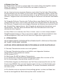
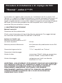
Procéduretypique de stérilisation en place d’un filtre sec
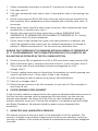
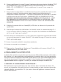
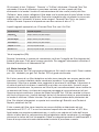
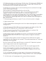
Le montage recommandé du filtre est présenté Figure 1. Des manomètres permettant
une mesure précise entre 0 et 3 bar doivent être installés afin de mesurer la pression de
vapeur et la pression différentielle dans le filtre durant le cycle de stérilisation àla vapeur.
Afin d’obtenir uns stérilisation efficace, la pression de vapeur ( mesurée en position T)
dans le système doit être maintenue à 121°C (1,1 bar de vapeur saturée) pendant la
durée minimum validée par l’utiilsateur qui permet d’obtenir la stérilité du système.
14

15
Figure1:Montage recommandé du boitier filtre pour la
stérilsation en place du système sec
P
1
P
2
T
C
DRAINAGE D E
NOVASIP
FILTRE
AIR/N
P
3
F
A
B
P
4
DRAINAGE I
2
EVENT G
DRAINAGE J
PROCESS
PROCESS
VAPEUR
P= MANOMÈTRE
T=THERMOCOUPLE
CETTE PORTION DOIT ÊTRE
RÉDUITE AU MINIMUM
1. Suivreles instructions de la section 3.1 et vérifier que toutes les vannes sont fermées
2. Ouvrir totalement la vanne C
3. Ouvrir totalement la vanne de purge du condensat ou la vanne I, les vannes J et G
du corps de filtre
4. Régler la pression de vapeur (P4) à 300 mbar au dessus de la pression de vapeur
requise. Une fois les condensats purgés en I , fermer partiellement la vanne I
(si nécessaire)
5. Ouvrir lentement la vanne B pour fairepénétrer la vapeur dans le système. Une fois
les condensats purgé en J, fermer partiellement la vanne J.

6. Fermer partiellement la vanne G quand la présence de vapeur devient évidente,TOUT
EN S’ASSURANT QUE LA PRESSION EN P2 NE DIFFERE PAS DE PLUS DE300
MBAR DE LA PRESSION P1. Ouvrir partiellement la vanne D pour purger les
condensats.
7. Faire circuler la vapeur dans le système jusqu’à ce que la pression de vapeur se soit
stabilisée et ajuster l’alimentation en vapeur régulée jusqu’àobtention de la
température validée en position T . Contrôler la température au niveau de T pendant
la durée nécessaireàla stérilisation. S’ASSURER QUE LA PRESSION EN P2 NE
DESCEND PAS DE PLUS DE 300 MBAR AU-DESSOUS DE CELLE DE P1. IL EST
RECOMMANDE DE FAIRE SUIVRE LA STERILISATION A LA VAPEUR PAR UNE
MISE SOUS PRESSION D’AIR TELLE QUE DECRITE DANS LES PARAGRAPHES
SUIVANTS.
8. Prérégler la pression d’air ou d’azote(P3) à 200 mbar au dessus de la pression de
vapeur (P4).
9. Une fois que le temps de stérilisation s’est écoulé, fermer les vannes de purge D, J
et I et la vanne d’évent G. Couper l’arriver de vapeur B, et introduire immédiatement
de l’air ou de l’azote par la vanne F.
10. Pour faciliter le refroidissement, la vapeur peut être purgée de l’ensemble de filtration
en ouvrant doucement la vanne d’évent G et la vanne de purge J. Fermer les vannes
Get J après cette purge.
11. Laisser l’ensemble refroidir à température ambiante.
12. Fermer la vanne d’air ou d’azote F
13. Dépressuriser l’ensemble de filtration par l’intermédiaire de la vanne d’évent G. Le
sytème filtrant est prît à être utilisé.
6. REMPLACEMENT DU BOITIER FILTRE :
Le boitier filtredoit être remplacé lorsque la pression différentielle maximale admissible a
été atteinte ( cf la documentation correspondante), lorsque le débit n’est plus aceptable,
lorsque la durée maximale de stérilisation a été atteinte, ou le filtreendommagé quelque
soit l’ordredans lequel l’évènement se produit. Jeter le boitier filtreen respectant la
règlementation locale en vigueur. Il ne faut pas essayer de nettoyer le boitier filtre.
7. SERVICES ET LABORATOIRES SCIENTIFIQUES :
Pall possède un service technique pour vous assister dans l’utilisation des filtres. Ce
service est disponible àtitre gracieux dans le monde entier, et nous sommes heureux de
répondre àtoutes vos questions. De plus, notre réseau d’ingénieurs commerciaux est
aussi à votre service.
16

17
Montage- und Installationsanleitung für "Novasip"
Filtereinheiten für Artikelnummern C****P1
PALL “Novasip” Komplettfilter werden gemäß nachfolgend beschriebener
Vorgehensweise montiert und eingebaut. Diese Anleitung sollte vollständig gelesen
werden, da sie wertvolle Informationen enthält, die auf langjähriger Erfahrung basieren.
Die Anweisungen sollten genauestens befolgt und, wenn möglich, in die Standard-
Arbeitsabläufe des Anwenders integriert werden. Sollten irgendwelche Anweisungen
nicht in Ihren Arbeitsablauf passen, wenden Sie sich bitte an PALL oder Ihren Händler vor
Ort, bevor Sie Ihr System vervollständigen.
1. SPEZIFIKATIONEN
Werkstoff:
Filtergehäuse: Polyetherimid
Weitere Materialien abhängig vom Typ des gewünschten Novasip-Filters. Nähere
Einzelheiten entnehmen Sie bitte den PALL-Druckschriften USD1647 und USD1648.
Bei Einsatz in Gasen und Flüssigkeiten
Zulässiger Betriebsüberdruck bei 40°C
in kompatiblen Flüssigkeiten: 6,5 bar
Max. zulässiger Differenzdruck: siehe entsprechendes PALL- Datenblatt
Einlaß-/Auslaß-Anschlüsse: 1”/1 1/2”, passend für “Triclover”
Entlüftungsventil: Schnellverschlußnippel, passend zu
Kupplungen Typ RBE 03.1906 von Stäubli
Entleerungsventil: Schlauchtülle 5-7 mm
VORSICHT: NOVASIP KOMPLETTFILTER SOLLTEN NICHT IN FLÜSSIGKEITEN
EINGESETZT WERDEN, DIE NICHT MIT DEM GEHÄUSEWERKSTOFF KOMPATIBEL
SIND; DIES GILTAUCH FÜR REINIGUNGSMITTEL. INKOMPATIBLE FLÜSSIGKEITEN
SIND SOLCHE, DIE DEN GEHÄUSEWERKSTOFF ANGREIFEN, AUFWEICHEN, ZUM
BERSTEN BRINGEN ODER ANDERWEITIG BEEINTRÄCHTIGEN. DER ANWENDER
SOLLTE SICH VOR EINSATZ DES FILTERS ÜBER DIE KOMPATIBILITÄT DER
PROZESSFLÜSSIGKEIT VERGEWISSERN.
Es unterliegt der Verantwortung des Anwenders, die tatsächlichen Betriebsbedingungen
zu überprüfen und sicherzustellen, daß die Filtereinheit der Anwendung angemessen ist
und den örtlichen Sicherheitsbedingungen entspricht.

18
2. AUFBEWAHRUNG
a) Lagern Sie die Komplettfilter in einem sauberen, trockenen Raum ohne direkte
Sonneneinstrahlung - möglichst in dem Karton, in dem sie geliefert werden.
b) Nehmen Sie den Filter ERST aus seiner Schutzfolie, wenn er eingesetzt werden soll.
c) Stellen Sie sicher, daß der Filter für die Anwendung geeignet ist. Zusätzlich zur
Artikel-Nr. ist jede Filtereinheit durch eine individuelle Chargen- und Einzelnummer
gekennzeichnet.
WICHTIG: NOVASIP FILTEREINHEITEN SOLLTEN VOR DEM EINSATZ AUF
ANZEICHEN VON BESCHÄDIGUNG KONTROLLIERTWERDEN. BEI EINSATZ ÜBER
LÄNGERE ZEITRÄUME SOLLTE DER FILTER MINDESTENS WÖCHENTLICH
ÜBERPRÜFT WERDEN. BEI BESCHÄDIGUNGEN ODER FUNKTIONSSTÖRUNGEN
SOLLTE DER FILTER AUSGETAUSCHT WERDEN.
3. INSTALLTION UND BETRIEB
3.1 Installtion
Vor Einsatz des Filters ist es unerläßlich zu überprüfen, ob der gewählte Filtertyp für das
Gas oder die zu filtrierende Flüssikeit geeignet ist. Die nachfolgenden Anweisungen
sollten genau befolgt werden.
a) Installieren Sie den Filter unter Verwendung der passenden Anschlüsse in Ihr System.
b) Der Filter muß in Fließrichtung installiert werden; orientieren Sie sich an dem
Richtungspfeil auf dem Filtergehäuse.
c) Der Filter sollte so positioniert werden, daß Entlüftung und Entleerung vor und
während des Betriebes möglich ist.
d) Der Filter sollte so installiert werden, daß bei Bedarf ein Integritätstest durchgeführt
werden kann.
e) Wenn hinter dem Filter ein Überdruck vorliegt, kann der Einsatz eines
Rückschlagventils sinnvoll sein, um Schäden durch Rückdruck zu vermeiden.
f) Woextreme Druckschwankungen vorkommen, sollte der Filter durch einen
vorgeschalteten Pufferbehälter geschützt werden.
g) Wenn hinter dem Filter ein Schnellverschlußventil vorhanden ist, besteht die Gefahr,
daß der Filter durch Druckstöße beschädigt wird. Ist dies der Fall, sollte der
Filter durch einen Pufferbehälter zwischen Ventil und Filter geschützt werden.
h) Gewichtsbelastungen seitlich und am Filterende sollten bei Einbau und Betrieb
vermieden werden.
i) Achten Sie darauf, daß der Filter sich während der Sterilisation ausdehnen kann.

k) Zu festes Anziehen der Triclover-Klammern am Ein- und Auslaß kann zu deren
Beschädigung bei hohen Temperaturen führen. Es wird empfohlen, die Klammern nur
von Hand anzuziehen, und sie dann mit einer viertel Drehung zu lösen.
VORSICHT: NOVASIP FILTEREINHEITEN SIND VALIDIERT FÜR DEN EINSATZ IN
DRUCKLUFT-SYSTEMEN UND FÜR IN-SITU DAMPFSTERILISATIONEN. DAHER
SOLLTEN DIE FÜR DIE ARBEIT MIT DRUCK UND HOHEN TEMPERATUREN
ERFORDERLICHEN SICHERHEITSVORKEHRUNGEN ZUM SCHUTZ DES
PERSONALS GETROFFEN WERDEN, D.H. ES SIND SCHUTZBRILLEN UND -
HANDSCHUHE ZU TRAGEN. PALL EMPFIEHLT DARÜBER HINAUS DIE
VERWENDUNG EINES GESICHTSSCHUTZES FÜR DEN FALL, DASS AUFGRUND
EINER LECKAGE ODER BEI ETWAIGEM BERSTEN DAMPF AUSTRITT.
3.2 Betrieb
Bei Installation und vor dem Sterilisieren mit Dampf sollte der Filter auf Unversehrtheit
überprüft werden.
Bei Anwendung in Flüssigkeiten muß der Filter beim erstmaligen Anströmen entlüftet
werden, indem das Entlüftungsventil geöffnet wird. Schließen Sie das Ventil, sobald
Flüssigkeit austritt.
4. INTEGRITÄTSTEST
Die Integrität des Filters sollte vor und nach der Filtration durch einen geeigneten Test
überprüft werden. Je nach Filtertyp und Rückhalterate kann der Pall ForwardFlow-Test,
der Wasserintrusionstest (WIT) oder der Bubble-Point-Test angewandt werden.
4.1 ForwardFlow-Test
Der Pall Forward Flow-Test kann an einer sterilen oder nicht sterilen Filtereinheit
durchgeführt werden. Dieser Test eignet sich für alle Pall Sterilfilter und andereFeinfilter
zur Partikelabscheidung.
Der Test erfordert einen durch Druckluft oder Stickstoff erzeugten, definierten Testdruck
auf der Unreinseite einer benetzten Membran. Aufgrund dieses angelegten Druckes setzt
ein Gasfluß ein, welcher durch die Diffusion der Gasmoleküle durch die Membran
resultiert. Pall hat die Volumenmessung dieses Gasflusses mit den Ergebnissen von
Bakterienrückhaltetests korreliert, um die Überprüfung der Integrität des Filterelements zu
ermöglichen.
Die Testgeräte “Palltronic”, “Flowstar” oder “TruFlow” führen den Forward Flow-Test
durch, indem bei konstantem Druck der diffusive Fluß von der unreinen Seite her
gemessen wird. Die Gefahr einer Kontamination der sterilen Seite wird damit
ausgeschlossen. Das Palltronic Testgerät wirdnach erfolgtem Benetzen der Membran am
obersten Punkt des Komplettfilters angeschlossen. Nach Eingabe der geforderten
Informationen und Testparameter führt das Gerät den Integritätstest vollautomatisch
durch und dokumentiert das Ergebnis. Während der Testphase sollte die Temperatur
nicht mehr als + 1°C schwanken.
19

Geeignete Netzflüssigkeiten für den Forward Flow-Test an Pall-Filtern:
*Isopropylalkohol (IPA)
In vielen Fällen ist es einfacher, den Filter zu testen, wenn er mit der entsprechenden
Prozeßflüssigkeit benetzt ist. Dies ist fast immer möglich; der Wissenschaftliche Labor-
und Beratungsdienst (SLS) von Pall hilft Ihnen bei Fragen hierzu gerne weiter.
4.2 Wasserintrusionstest (WIT)
Der Pall Wasserintrusionstest wird an sterilen, hydrophoben Filtereinheiten durchgeführt.
Dieser Test eignet sich für die Pall Filterelemente des Typs “Emflon PFR”.
Wird die unreine Seite eines trockenen hyrophoben Filterelementes mit Wasser
beschlagen und mit Druck belastet, so verhindert die hydrophobe Natur der
Filtermembran so lange das Durchtreten des Wassers, bis der Intrusionsdruck erreicht
ist. Oberhalb dieses Druckes tritt eine kleine, aber meßbare Menge Wasser in Form von
Wasserdampf durch die Membran. Die Menge dieses durchtretenden Wassers ist
abhängig von der Menge und Größe der Poren. Dieses Prinzip bildet die Grundlage des
Wasserintrusionstests. Pall hat die Messung des Wasserflusses mit den Ergebnissen von
Bakterienrückhaltetests in Korrelation gebracht, so daß dieser Test als Nachweis der
Filterleistung verwendet werden kann. Nachdem die unreine Seite mit detilliertem oder
entmineralisiertem Wasser von 20°C (+ 2°C) beschlagen und der Testdruck angelegt
wurde, kann eine Absenkung des Wasserspiegels beobachtet werden. Dies ist auf
verschiedene Faktoren wie das Zusammendrücken der Membranfaltung oder Austreiben
der Luft in den Poren zurückzuführen. Diese Vorgänge sind innerhalb der
Stabilisierungszeit beendet, und es stellt sich ein unendlicher, stabiler Wasserfluß ein.
Nähere Informationen zu diesem Test können den wissenschaftlich-technischen Schriften
von Pall entnommen werden.
Die Testgeräte Palltronic Flowstar oder TruFlow führen den Wasserintrusionstest durch,
indem bei konstantem Druck der Wasserfluß von der unreinen Seite her gemessen wird.
Die Gefahr einerKontamination der sterilen Seite wird damit ausgeschlossen. Das
Palltronic-Testgerät wird am obersten Punkt des Komplettfilters angeschlossen. Nach
Eingabe der geforderten Informationen und Testparameter führt das Gerät den
Wasserintrusionstest vollautomatisch durch und dokumentiert das Ergebnis. Nach dem
Tests wird der Filter entleert, und ist meist wieder einsetzbar. Bei Anwendungen, bei
denen der Filter absolut trocken sein muß, ist noch ein Trocknungsvorgang erforderlich.
Filtermedium
Ultipor N66
N66 Posidyne
Fluorodyne II
Ultipor VFDV50
Emflon PFR
Netzflüssigkeit
Wasser, 60/40 (V/V) IPA*-Wasser-Gemisch
Wasser, 60/40 (V/V) IPA*-Wasser-Gemisch
Wasser, 60/40 (V/V) IPA*-Wasser-Gemisch
30/70 (V/V) IPA*-Wasser-Gemisch
60/40 (V/V) IPA*-Wasser-Gemisch, 25/75 t-Butylalkohol-Wasser-Gemisch
20

4.3 Bubble-Point-Test
Ein Bubble-Point-Test kann an sterilen oder nicht sterilen Filtern durchgeführt werden.
Dieser Test eignet sich für alle Pall Sterilfilter und andere Feinfilter zur
Partikelabscheidung.
Auf der Unreinseite einer benetzten Membran wird mittels Druckluft oder Stickstoff der
Druckstufenweise so weit erhöht, bis die ersten Poren freigeblasen werden. Da der Fluß
über diese freien Poren um ein Vielfaches höher ist als der Diffusionsfluß, detektiert das
Palltronic Testgerät einen nicht linearen Anstieg des Gasflusses und definiert den Bubble
Point.
Die Testgeräte Palltronic Flowstar oder TruFlow führen einen Bubble-Point-Test von der
unreinen Seite her durch, und schalten das Risiko einer Kontamination der Reinseite aus.
Das Palltronic-Testgerät wird nach erfolgtem Benetzen der Membran am obersten Punkt
des Komplettfilters angeschlossen. Nach Eingabe der geforderten Informationen und
Testparameter führt das Gerät den Bubble-Point-Test vollautomatisch durch und
dokumentiert das Ergebnis.
In vielen Fällen ist es einfacher, den Filter zu testen, wenn er mit der entsprechenden
Prozeßflüssigkeit benetzt ist. Dies ist fast immer möglich; der Wissenschaftliche Labor-
und Beratungsdienst (SLS) von Pall hilft Ihnen bei Fragen hierzu gerne weiter.
5. STERILISATION
DIE NOVASIP EINWEG-FILTEREINHEITEN KÖNNEN IN-SITU ODER IM AUTOKLAVEN
MIT DAMPF STERILISIERT WERDEN.
ACHTUNG: STERILISIEREN SIE DEN FILTER NIEMALS IN DER PLASTIKHÜLLE.
5.1 Novasip Filtereinheiten werden nicht steril geliefert.
5.2 Novasip Filtereinheiten sollten ausschließlich nach folgendem Verfahren
dampfsterilisiert oder autoklaviert werden:
(a) Bis maximal 142°C
(b) Sterilisieren Sie NIE bei höheren Temperaturen.
(c) Zu spezifischen Dampfsterilisationsbedingungen wenden Sie sich bitte an Pall.
(d) Ein beschleunigtes Herunterkühlen empfielt sich nicht.
5.3 Detaillierte Angaben zur Sterilisation von Pall Filtern entnehmen Sie bitte der Pall
Druckschrift USD805. Eine typische Vorgehensweise für die in-situ Sterilisation eines
trockenen Filters ist nachfolgend beschrieben. Für weitere Einzelheiten wenden Sie
sich bitte an Pall.
5.4 Für Gasfilter wird ein numerierter Kunststoffring geliefert, auf dem bei Bedarf die
Anzahl der durchgeführten Sterilisationszyklen notiert werden kann.
21
La pagina si sta caricando...
La pagina si sta caricando...
La pagina si sta caricando...
La pagina si sta caricando...
La pagina si sta caricando...
La pagina si sta caricando...
La pagina si sta caricando...
La pagina si sta caricando...
La pagina si sta caricando...
La pagina si sta caricando...
La pagina si sta caricando...
La pagina si sta caricando...
La pagina si sta caricando...
La pagina si sta caricando...
La pagina si sta caricando...
La pagina si sta caricando...
La pagina si sta caricando...
La pagina si sta caricando...
La pagina si sta caricando...
La pagina si sta caricando...
La pagina si sta caricando...
La pagina si sta caricando...
La pagina si sta caricando...
La pagina si sta caricando...
La pagina si sta caricando...
La pagina si sta caricando...
La pagina si sta caricando...
La pagina si sta caricando...
La pagina si sta caricando...
La pagina si sta caricando...
La pagina si sta caricando...
-
 1
1
-
 2
2
-
 3
3
-
 4
4
-
 5
5
-
 6
6
-
 7
7
-
 8
8
-
 9
9
-
 10
10
-
 11
11
-
 12
12
-
 13
13
-
 14
14
-
 15
15
-
 16
16
-
 17
17
-
 18
18
-
 19
19
-
 20
20
-
 21
21
-
 22
22
-
 23
23
-
 24
24
-
 25
25
-
 26
26
-
 27
27
-
 28
28
-
 29
29
-
 30
30
-
 31
31
-
 32
32
-
 33
33
-
 34
34
-
 35
35
-
 36
36
-
 37
37
-
 38
38
-
 39
39
-
 40
40
-
 41
41
-
 42
42
-
 43
43
-
 44
44
-
 45
45
-
 46
46
-
 47
47
-
 48
48
-
 49
49
-
 50
50
-
 51
51


Pall "Novasip" Filter Assemblies Step-by-Step Guide
- Tipo
- Step-by-Step Guide
in altre lingue
- français: Pall "Novasip" Filter Assemblies
- español: Pall "Novasip" Filter Assemblies
- Deutsch: Pall "Novasip" Filter Assemblies
- svenska: Pall "Novasip" Filter Assemblies
Documenti correlati

Altri documenti
-
SciCan STATIM 5000S Manuale utente
-
AEG VX9-1-SB-E Manuale del proprietario
-
Medtronic Puritan Bennett Re/X700 expiratory bacteria filter Manuale utente
-
 RainSoft HDINSTIUDWS Manuale utente
-
-
ARIETE Moka Aroma 1337/41 Manuale utente
-
Braun 42194 Manuale utente
-
-
Electrolux UltraCaptic EUC96DBM Manuale utente
-
 Kromschroder PFP 700, PFR 704 Istruzioni per l'uso

