66250430 - V2.0 - 15/05/18
- 1 -
4000 Series
Art.4836 - Installation instructions
Art.4836 Speaker unit for audio door entry kits or little systems
A
BB
C
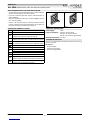
Fig. 1 Front
4836-0
4836-1
4836-2
4836-1D
4836-2D
Made in Italy
Stainless Steel Matte
Aluminium
High Brass
C
C1
P1
P2
S
S1
3
1
2
P3
P4
F
D
E
G
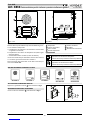
Fig. 2 Back
DESCRIPTION
Speaker unit for audio door entry kits or little systems.
The unit circuitry includes:
a. The transmitting amplier with condenser microphone and
volume control;
b. The receiving amplier and volume control;
c. 2 LEDs to illuminate the name plate (except Art.4836-0 model);
d. The lock release relay to enable the electric lock;
e. The modulated tone generator;
On speaker units Art.4836-0, Art.4836-1 and Art.4836-2 the P3
and P4 terminals will not be available.
LEGEND
A Loudspeaker
B Push buttons
C Card name holders
D Loudspeaker volume
E Microphone volume
F Microphone
G Connection terminals
CONTROLS
Loudspeaker volume
Adjust the loudspeaker volume.
Rotate clockwise to increase or anti-clockwise to decrease
Microphone volume
Adjust the microphone volume.
Rotate clockwise to increase or anti-clockwise to decrease
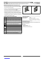
AVAILABLE VERSIONS AND BUTTONS LAYOUT
Art.4836-0
1
Art.4836-1
1
2
Art.4836-2
13
Art.4836-1D
13
4 2
Art.4836-2D
ADHESIVE GASKET PLACEMENT
Apply the Y seal as shown in Fig. 3.
ANTITAMPERING LOCKS FIXING
Fit the anti-tampering locks W as shown in Fig. 4.
Y
G
Fig. 3
W
Fig. 4

66250430 - V2.0 - 15/05/18
- 2 -
4000 Series
Art.4836 - Installation instructions
Art.4836 Speaker unit for audio door entry kits or little systems
HOW TO REMOVE/INSERT THE CARD NAME HOLDER
•To avoid damage to the module front plate, mask the side that
will be in contact with the screwdriver blade;
•Insert the screwdriver (at side) into the card-holder hole as
shown in Fig. 5;
•Move the screwdriver to the left as shown in Fig. 6 to extract
the card name holder;
•Edit the card name then replace it inside the holder and ret:
insert the holder inside its housing from the left or right side
then push the other side until it clips into place. Fig. 5 Fig. 6
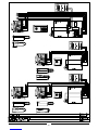
CONNECTION TERMINALS SIGNALS
CPush buttons common
C1 Electronic call tone output (active only on call)
P1 Output call button 1
(available on all versions except Art.4836-0)
P2 Output call button 2
(available only on Art.4836-2 and Art.4836-2D versions)
SNormally open relay contacts (the contact between S and
S1 is closed when the unit receives the “door open” signal
S1
Power supply input 0V
3Speech Ground output
1Speech input
“Door Open” signal
Power supply input 13Vac
2Speech output
P3 Output call button 3
(available only on Art.4836-1D and Art.4836-2D versions)
P4Output call button 4
(available only on Art.4836-2D version)
TECHNICAL SPECIFICATION
Power Supply: 13Vac
Power consumption: Stand-by: approx. 25mA
During a call: approx. 150mA
During a conversation: approx 70mA
Working Temperature: -10 +50 °C
CLEANING OF THE PLATE
Use a clean and soft cloth. Use moderate warm water or non-ag-
gressive cleansers.
Do not use:
• abrasive liquids;
• chlorine-based liquids;
• metal cleaning products.

66250430 - V2.0 - 15/05/18
- 3 -
Serie 4000
Art.4836 - Istruzioni di installazione
Art.4836
Portiere elettrico per kit citofonici o piccole installazioni in genere
A
BB
C
Fig. 1 Fronte
4836-0
4836-1
4836-2
4836-1D
4836-2D
Made in Italy
Stainless Steel Matte
Aluminium
High Brass
C
C1
P1
P2
S
S1
3
1
2
P3
P4
F
D
E
G
Fig. 2 Retro
DESCRIZIONE
Portiere elettrico per kit citofonici o piccole installazioni in genere.
La sua elettronica comprende:
a. L’amplicatore di trasmissione con microfono a condensatore
e regolazione del volume;
b. L’amplicatore di ricezione con altoparlante da 0,5W e regola-
zione del volume;
c. 2 LED d’illuminazione cartellini (escluso Art.4836-0);
d. Il relè d’asservimento per l’attivazione della serratura elettrica;
e. Il circuito di generazione della nota elettronica.
Nelle versioni Art.4836-0, Art.4836-1 e Art.4836-2 non sono pre-
senti i morsetti P3 e P4.
LEGENDA
A Altoparlante
B Pulsanti di chiamata
C Porta cartellini
D Volume altoparlante
E Volume microfono
F Microfono
G Morsetteria di connessione
REGOLAZIONI
Volume altoparlante
Regolazione del volume dell’altopalralte.
Ruotare in senso orario per aumentare o antiorario per diminuire
Volume microfono
Regolazione del volume del microfono.
Ruotare in senso orario per aumentare o antiorario per diminuire
VERSIONI DISPONIBILI E ORDINE PULSANTI
Art.4836-0
1
Art.4836-1
1
2
Art.4836-2
13
Art.4836-1D
13
4 2
Art.4836-2D
APPLICAZIONE GUARNIZIONE ADESIVA
Applicare la guarnizione adesiva Y come mostrato in Fig. 3.
INSERIMENTO FERMI ANTIEFFRAZIONE
Inserire i fermi anti-erazione W come mostrato in Fig. 4.
Y
G
Fig. 3
W
Fig. 4

66250430 - V2.0 - 15/05/18
- 4 -
Serie 4000
Art.4836 - Istruzioni di installazione
Art.4836 Portiere elettrico per kit citofonici o piccole installazioni in genere
RIMOZIONE/INSERIMENTO DEL PORTACARTELLINO
•Per evitare ammaccature della placca frontale, proteggere il
lato che verrà in contatto con la lama del cacciavite utilizzan-
do una striscia di nastro isolante;
•Inserire il cacciavite (lato piatto della lama) nell’apposita fes-
sura del porta cartellino come mostrato in Fig. 5;
• Fare leva con il cacciavite come mostrato in Fig. 6 per rimuovere il
porta-cartellino (fare attenzione a non ammaccare la placca);
•Modicare il cartellino e riporlo all’interno del porta-cartelli-
no quindi riposizionare lo stesso al suo posto inserendolo nel
suo alloggiamento dal lato destro o sinistro e premendo il lato
rimasto libero no all’aggancio (compiendo un movimento
contrario a quello fatto per estrarlo).
Fig. 5 Fig. 6
SEGNALI MORSETTERIA DI CONNESSIONE
CComune pulsanti
C1 Uscita nota elettronica (attiva durante la chiamata)
P1 Uscita pulsante 1
(disponibile in tutte le versioni eccetto la Art.4836-0)
P2 Uscita pulsante 2
(disponibile solo nelle versioni Art.4836-2 e Art.4836-2D)
SContatti relé normalmente aperto (il contatto tra S e S1 si
chiude al ricevimento del comando “apri-porta”)
S1
Ingresso alimentazione 0V
3Uscita massa fonica
1Ingresso fonia
Comando “apri-porta”
Ingresso alimentazione 13Vac
2Uscita fonia
P3 Uscita pulsante 3
(disponibile solo nelle versioni Art.4836-1D e Art.4836-2D)
P4Uscita pulsante 4
(disponibile solo nella versione Art.4836-2D)
SPECIFICHE TECNICHE
Tensione di lavoro: 13Vac
Assorbimenti: Stand-by: circa 25mA
Durante la chiamata: circa 150mA
Durante la conversazione: circa 70mA
Temperatura di lavoro: -10 +50 °C
PULIZIA DELLA PLACCA
Usare un panno morbido e pulito. Usare acqua tiepida o un de-
tergente non aggressivo.
Non usare:
• prodotti abrasivi;
• prodotti contenenti cloro;
• prodotti per la pulizia dei metalli.


MANUFACTURER
FABBRICANTE
FABRICANT
FABRICANTE
FABRIKANT
VIDEX ELECTRONICS S.P.A.
Via del Lavoro, 1
63846 Monte Giberto (FM) Italy
Tel (+39) 0734 631669
Fax (+39) 0734 632475
www.videx.it - inf[email protected]
CUSTOMER SUPPORT
SUPPORTO CLIENTI
SUPPORTS CLIENTS
ATENCIÓN AL CLIENTE
KLANTENDIENST
VIDEX ELECTRONICS S.P.A.
www.videx.it - technical@videx.it
Tel: +39 0734-631669
Fax: +39 0734-632475
UK Customers only:
VIDEX SECURITY LTD
www.videxuk.com
Tech Line: 0191 224 3174
Fax: 0191 224 1559
Main UK oce:
VIDEX SECURITY LTD
1 Osprey Trinity Park
Trinity Way
LONDON E4 8TD
Phone: (+44) 0870 300 1240
Fax: (+44) 020 8523 5825
www.videxuk.com
Northern UK oce:
VIDEX SECURITY LTD
Unit 4-7
Chillingham Industrial Estate
Chapman Street
NEWCASTLE UPON TYNE - NE6 2XX
Tech Line: (+44) 0191 224 3174
Phone: (+44) 0870 300 1240
Fax: (+44) 0191 224 1559
Greece oce:
VIDEX HELLAS Electronics
48 Filolaou Str.
11633 ATHENS
Phone: (+30) 210 7521028
(+30) 210 7521998
Fax: (+30) 210 7560712
www.videx.gr
Danish oce:
VIDEX DANMARK
Hammershusgade 15
DK-2100 COPENHAGEN
Phone: (+45) 39 29 80 00
Fax: (+45) 39 27 77 75
www.videx.dk
Benelux oce:
NESTOR COMPANY NV
E3 laan, 93
B-9800 Deinze
Phone: (+32) 9 380 40 20
Fax: (+32) 9 380 40 25
www.videx.be
Dutch oce:
NESTOR COMPANY BV
Business Center Twente (BCT)
Grotestraat, 64
NL-7622 GM Borne
www.videxintercom.nl
info@videxintercom.nl
El producto lleva la marca CE que demuestra su conformidad y puede ser
distribuido en todos los estados miembros de la unión europea UE.
Este producto cumple con las Directivas Europeas 2014/30/EU (EMC);
2014/35/EU (LVD); 2011/65/EU (RoHS): marca CE 93/68/EEC.
Het product heeft de CE-markering om de conformiteit ervan aan te tonen en
is bestemd voor distributie binnen de lidstaten van de EU zonder beperkin-
gen. Dit product volgt de bepalingen van de Europese Richtlijnen 2014/30/EU
(EMC); 2014/35/EU (LVD); 2011/65/EU (RoHS): CE-markering 93/68/EEG.
Le produit est marqué CE à preuve de sa conformité et peut être distribué
librement à l’intérieur des pays membres de l’union européenne EU.
Ce produit est conforme aux directives européennes 2014/30/EU (EMC) ;
2014/35/EU (LVD) ; 2011/65/EU (RoHS): marquage CE 93/68/EEC.
The product is CE marked demonstrating its conformity and is for distribution
within all member states of the EU with no restrictions. This product follows
the provisions of the European Directives 2014/30/EU (EMC); 2014/35/EU
(LVD); 2011/65/EU (RoHS): CE marking 93/68/EEC.
Il prodotto è marchiato CE a dimostrazione della sua conformità e può essere
distribuito liberamente all’interno dei paesi membri dell’Unione Europea UE.
Questo prodotto è conforme alle direttive Europee: 2014/30/UE (EMC);
2014/35/UE (LVD); 2011/65/UE (RoHS): marcatura CE 93/68/EEC.
-
 1
1
-
 2
2
-
 3
3
-
 4
4
-
 5
5
-
 6
6
-
 7
7
-
 8
8


in altre lingue
- English: Videx 4000 SERIES User manual
- français: Videx 4000 SERIES Manuel utilisateur