Videx 6200 Series Manuale utente
- Categoria
- Impianti citofonici
- Tipo
- Manuale utente
Questo manuale è adatto anche per

66251130 - V2.0 - 31/05/18
- 1 -
6200 Series
Art.6256 - Installation instructions
Art.6256 3.5" colour videophone
27 mm 144 mm
182 mm
Fig. 1
+V
-
1
2
V1
V2
24Vac
0Vac
SW1
SW2
PT3 PT2
PT1
SW1
LB
SB
LD
2A
3A
4A
5A
A
D
B
C
E
GF
Fig. 2
DESCRIPTION
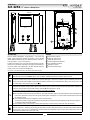
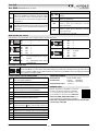
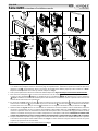
Surface mount videophone incorporating a 3.5” Hi-Res full
colour active matrix LCD monitor specic for “6 wire” videokit
(VK4K, VRVK and VK8K range). It includes 4 buttons: “camera re-
call”, “open door” , “service” and “privacy”.
2 LED’s* indicate the privacy activated and open door. Program-
mable privacy duration and number of rings. Intercommunicat-
ing call and door call. Adjustments: call tone volume switch (3
levels), picture hue, contrast and brightness.
* The operation of some LED’s and the functions described may require additional cabling
LEGEND
A
Connection terminals
B
8 Way dip switch bank
C
2 Way dip switch bank
D
Contrast adjustment trimmer
E
Hue adjustment trimmer
F
Brightness control
G
Call tone volume switch
PUSH BUTTONS
Service push button
Shorts the “SB” terminal to GROUND (open collector 24Vdc 100mA max) while the button remain pressed.
Camera recall button
Pick up the handset then press the button (Press once for door/gate 1, twice for 2 and so on up to a maximum of 4 entranc-
es): the relevant LED switches ON and the monitor switches on showing the video from the door panel. The speech is also
live and the door can be opened by pressing .
Door-open / intercommunicating call button
With the handset lifted and speech lines open to the entrance panel, press this button to open the door. If the terminal “LD”
is properly connected the relevant LED remains switched ON until the door is closed.
Intercommunication only works when the system is in stand-by condition.
Switch 4 of the SW1 dip-switch selects the type of intercommunication:
OFF Intercommunication between two apartments - pick up the handset and press the key button to call the videophone(s)
in the other apartment. A busy tone will signal that the other videophone is in conversation with the door station and
so cannot be called.
ON Intercommunication between videophones in the same apartment
- pick up the handset and press the key button one, two, three or four times to call videophone with extension address 1, 2,
3 or 4 (Set on dip-switch 2&3 of SW1).
Any intercommunicating conversation is always interrupted by an external call (i.e. External calls take priority).
Privacy ON-OFF button
When the system is in stand-by, the pressing of this button activates (LED switched on) or disables (LED switched o) the
“privacy” service. The service is automatically disabled when the programmed privacy time expires. When the service is
enabled the videophone does not receive calls.

66251130 - V2.0 - 31/05/18
- 2 -
6200 Series
Art.6256 - Installation instructions
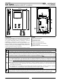
LEDS
Door open LED
Can be used to indicate the status of a door or gate. It re-
quires a switched 12Vdc connection to terminal “LD”.
Privacy ON/OFF LED
When the videophone is in stand-by, this LED signals
the privacy service status
(ON = service enabled, OFF = service disabled).
CONTROLS
SW1
Call tone volume switch
(3 levels).
PT1
Brightness control
(sliding wheel).
PT2
Hue adjustment trimmer
(rotate left to increase or right to decrease).
PT3
Contrast adjustment trimmer*
(rotate left to increase or right to decrease).
*Not available in some LCD versions.
SETTINGS DIPSWITCH
The videophone setup is carried out by the 2 dip-switch banks.
Switches 1 Apartment Address
OFF 1
ON 2
Switches 2,3 Extension Address
OFF OFF 1
ON OFF 2
OFF ON 3
ON ON 4
Switch 4 Intercommunication
OFF Between videophones of the two
apartment
ON Between videophones in the
same apartment
Switches 5,6 Number of rings
OFF OFF 2
ON OFF 4
OFF ON 6
ON ON 8
Switches 7,8 Privacy duration time
OFF OFF 15 minutes
ON OFF 1 hours
OFF ON 4 hours
ON ON 8 hours
2 WAY DIPSWITCH SW2
The two way dip-switch adjusts the impedance of the video signal. The default setting is “ON” for both switches
(75 Ohm): when there are more videophones in parallel connection (without video distributor) both switches
must be “ON” only on the last videophone (looking at the connection order) while for all other videophones
both switches must be set to “OFF”.
CONNECTION TERMINALS SIGNALS
+V
20Vdc Input/Output (As input 16÷20Vdc 0,5A – as out-
put 20Vdc 0,5A max)
Ground reference for +V terminal.
1
Speech line output from handset’s microphone and data
signal (Approx. 12V in stand-by, 5V during a conversation)
2
Speech line input toward the handset’s loudspeaker (Ap-
prox. 12V in stand- by, approx. 3V during a conversation)
V1 Balanced video signal 1 sync.-
V2 Balanced video signal 2 sync.+
24Vac 1A max power input
LB Local call input (5V in standby, 0V to trigger)
SB
Service button (open collector) active low output. The
button goes active when the button is pressed (Open
Collector 24Vdc 100mA max)
LD 12Vdc input for door-open LED
2A
Speech line input toward the loudspeaker of the parallel tele-
phone (Approx. 12V in stand-by, 3V during a conversation)
3A Output switched ground for parallel telephone
4A Output call tone for parallel telephone
5A Input for door-open command from parallel telephone
TECHNICAL SPECIFICATION
Power Supply: Supplied by the BUS line, 20Vdc
Power consumption: Stand-by: 50mA Max
Operating: 200mA Max
Working Temperature: -10 +50 °C
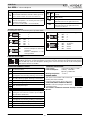
MEMORY BOARD
This device is also available in the version with
memory board (Art.6256/VM).
If you have that version, please refer to the
“6200, 6300, 6400 and 6700 Series Memory
Board” user manual (in English and Italian) for
installation and use.
The manual is available for download: click/tap or scan the
QR code.
Art.6256 3.5" colour videophone

66251130 - V2.0 - 31/05/18
- 3 -
6200 Series
Art.6256 - Installation instructions
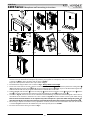
6200 Series Videophone wall mounting instructions
1
2
A
A
Fig. 1
Fig. 2
135cm
Fig. 3
B
C
C
E
B
G
F
D
G
G
D
Fig. 4
A
B
H
Fig. 5
2
1
Fig. 6
Fig. 7
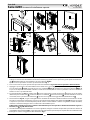
1. In order to install the videophone, it is necessary to remove the cover, which contains all the electronics, from the base: rstly
disconnect the handset from the videophone (by removing its plug from the videophone) then insert a 5.5mm at screw driv-
er into the clip
A
then rotate clockwise until you listen a “CLICK!”.
Repeat the same operation with the other clip as shown in Fig. 1.
2. Pull outwards the top part of the cover as shown in Fig. 2. Don’t pull the cover straight.
3. Put the base of the unit on the wall at approx 135cm from the nished oor (Fig. 3) to mark the points for the xing holes
B
(Fig. 4) remembering that the wires
E
(Fig. 4) must be fed through the hole
F
(Fig. 4). If you use the ush mounting box 503,
embed it into the wall vertically at approx. 140cm from the nished oor and the base.
4. Following Fig. 4, make the holes
B
, insert the wall plugs
C
and x the base with the screws
D
feeding the wires
E
into the
hole
F
. If you have used the box 503, x the base to the wall through the holes
G
using the screws
D
.
5. As shown in Fig. 5A, connect the wires to the removable terminals following the provided installation diagram. Connect the ter-
minal blocks to the electronics contained in the cover as shown in Fig. 5B. Reinsert the handset and test system before closing.
Note: Contrast and hue trimmers can be adjusted only if the videophone is open. Note while testing the system, it is
advisable to hold the cover with your hand closing manually the hook switch of the handset (see Fig. 5B reference
H
).
6. Once testing is complete and all the necessary adjustments are made, disconnect the handset from the cover and close the unit
as shown in Fig. 6: rst hook it on the bottom then push in the top until you hear a “CLICK!”.
7. Reconnect the handset and hang it as shown in Fig. 7.

66251130 - V2.0 - 31/05/18
- 4 -
Serie 6200
Art.6256 - Istruzioni di installazione
Art.6256 videocitofono 3,5" a colori
27 mm 144 mm
182 mm
Fig. 1
+V
-
1
2
V1
V2
24Vac
0Vac
SW1
SW2
PT3 PT2
PT1
SW1
LB
SB
LD
2A
3A
4A
5A
A
D
B
C
E
GF
Fig. 2
DESCRIZIONE
Videocitofono montaggio da supercie con monitor a colori alta
risoluzione LCD TFT da 3,5” specico per Videokit “6 li” (gamme
VK4K, VRVK e VK8K). Sono presenti 4 pulsanti: “auto-accensione”,
“apri-porta”, “servizio” e “privacy”.
2 LED* segnalano la privacy attiva e la porta aperta. Durata pri-
vacy e numero di squilli programmabili. Chiamata intercomu-
nicante e chiamata al piano. Regolazioni: volume suoneria (3
livelli), saturazione, luminosità e contrasto.
* Alcuni LED possono richiedere cablaggi aggiuntivi per funzionare correttamente
LEGENDA
A
Morsettiera di connessione
B
Dip-switch ad 8 vie
C
Dip-switch a 2 vie
D
Trimmer di regolazione del contrasto
E
Trimmer di regolazione saturazione colore
F
Regolazione luminosità
G
Switch volume tono di chiamata (3 livelli)
PULSANTI
Pulsante di servizio
Chiude il morsetto “SB” (open collector 24Vdc 100mA max) verso massa per tutto il tempo che resta premuto.
Pulsante di auto-accensione
Sollevare la cornetta e premere il pulsante (una volta per il posto esterno 1, due volte per il posto esterno 2 e così via no
a 4 ingressi): il relativo LED si accende insieme al monitor che mostra il video proveniente dall’esterno. La fonia verso l’e-
sterno è attiva ed è possibile aprire la porta premendo il pulsante chiave .
Pulsante apri-porta/chiamata intercomunicante
Con la cornetta sollevata a seguito di una risposta o di una auto-accensione, premere questo pulsante per aprire la porta. Il
relativo LED segnala lo stato di apertura della porta se il morsetto “LD“ sulla scheda di connessione è stato opportunamente
collegato. Come pulsante di chiamata intercomunicante è operativo solo quando il sistema è in stand-by.
La modalità intercomunicante dipende dalla posizione dello switch 4 dell’SW1:
OFF Intercomunicazione solo tra appartamenti - sollevare la cornetta e premere il pulsante chiave per chiamare il videocitofono
nell’altro appartamento. Un eventuale tono di occupato segnala che l’altro appartamento è in conversazione con l’esterno.
ON Intercomunicazione solo tra videocitofoni dello stesso appartamento - sollevare la cornetta e premere il pulsante chiave 1,
2, 3 o 4 volte per chiamare il videocitofono con indirizzo d’interno 1, 2, 3 o 4.
Qualsiasi conversazione intercomunicante è sempre interrotta da una chiamata esterna.
Pulsante “privacy” ON-OFF
In stand-by, questo pulsante attiva (LED acceso)/disattiva (LED spento) la funzione “privacy”, in ogni caso la funzione si disattiva
automaticamente allo scadere del tempo programmato. Con il servizio attivo il videocitofono non riceve le chiamate.

66251130 - V2.0 - 31/05/18
- 5 -
Serie 6200
Art.6256 - Istruzioni di installazione
LED
Door open LED
Può essere utilizzato per qualsiasi genere di segna-
lazione (di norma lo stato di apertura/chiusura della
porta). Richiede una connessione adeguata al tipo di
segnalazione.
Privacy ON/OFF LED
Quando il videocitofono è in stand-by segnala lo stato
di attivazione (accesi) /disattivazione (spento) del ser-
vizio privacy.
CONTROLLI E REGOLAZIONI
SW1
Regolazione volume della nota elettronica
(3 livelli).
PT1
Regolazione luminosità
(rotella di regolazione).
PT2
Trimmer di regolazione della saturazione
(ruotare a sinistra per incrementare o a destra
per decrementare).
PT3
Trimmer di regolazione contrasto*
(ruotare a sinistra per incrementare o a destra
per decrementare).
*Non disponibile su alcune versioni di LCD.
IMPOSTAZIONI DIPSWITCH
L’impostazione del videocitofono viene eseguita tramite i 2 banchi dip-switch.
Switch 1 Indirizzo d’appartamento
OFF 1
ON 2
Switch 2,3 Indirizzo interno
OFF OFF 1
ON OFF 2
OFF ON 3
ON ON 4
Switch 4 Intercomunicazione
OFF Tra i videocitofoni dei due appar-
tamenti
ON Tra i videocitofoni dello stesso
appartamento
Switch 5,6 Numero di squilli
OFF OFF 2
ON OFF 4
OFF ON 6
ON ON 8
Switch 7,8 Durata privacy
OFF OFF 15 minuti
ON OFF 1 ora
OFF ON 4 ore
ON ON 8 ore
DIPSWITCH A 2 VIE SW2
Il dip-switch a 2 vie serve per adattare l’impedenza del segnale video. L’impostazione di default è “ON” per entrambi
gli switch (75 Ohm): in presenza di più videocitofoni collegati in parallelo (senza distributore video), gli switch devono
rimanere entrambi ad “ON” solo per l’ultimo (in ordine di connessione) videocitofono, mentre per tutti gli altri devono
essere impostati entrambi ad “OFF”.
SEGNALI MORSETTERIA DI CONNESSIONE
+V
Ingresso/Uscita 20Vdc (come ingresso 16÷20Vdc 0,5A –
come uscita 20Vdc 0,5A max)
Riferimento di massa per il morsetto +V
1
Uscita fonia proveniente dal microfono della cornetta e se-
gnale dati (12V circa in stand-by, 5V circa in conversazione)
2
Ingresso fonia verso l’altoparlante della cornetta (12V
circa in stand-by, 3V circa in conversazione)
V1 Segnale video bilanciato 1 sinc.–
V2 Segnale video bilanciato 2 sinc.+
Ingresso d’alimentazione 24Vac 1A max
LB Ingresso per chiamata locale (5V stand by, 0V in funzione)
SB
Uscita pulsante di servizio di tipo attivo basso abilitata dalla
pressione del pulsante (Open collector 24Vdc 100mA max)
LD Ingresso 12Vdc per LED di segnalazione porta aperta
2A
Ingresso fonia verso l’altoparlante del citofono collegato in
parallelo (12V circa in stand-by e 3V circa in conversazione)
3A
Uscita commutata riferimento di massa citofono in parallelo
4A Uscita tono di chiamata per citofono in parallelo
5A Ingresso comando apri-porta citofono in parallelo
SPECIFICHE TECNICHE
Alimentazione: Fornita dal BUS, 20Vdc
Assorbimento: A riposo: 50mA Max
In funzione: 200mA Max
Temperatura di lavoro: -10 +50 °C
MEMORIA VIDEO
Questo dispositivo è disponibile anche nella
versione con memoria video (Art.6256/VM).
Se si è in possesso di questa versione, si pre-
ga di consultare il manuale utente “Memoria
video Serie 6200, 6300, 6400 e 6700” (in in-
glese e italiano) per l’installazione e l’utilizzo.
Il manuale è disponibile per il download: cliccare, fare tap o
scansionare il codice QR.
Art.6256 videocitofono 3,5" a colori

66251130 - V2.0 - 31/05/18
- 6 -
Serie 6200
Art.6256 - Istruzioni di installazione
Serie 6200 Istruzioni di installazione a parete
1
2
A
A
Fig. 1
Fig. 2
135cm
Fig. 3
B
C
C
E
B
G
F
D
G
G
D
Fig. 4
A
B
H
Fig. 5
2
1
Fig. 6
Fig. 7
1. Per installare il videocitofono è necessario aprirlo separando la base dal coperchio che ospita tutta l’elettronica dello stesso:
scollegare la cornetta dal videocitofono rimuovendo il relativo plug quindi inserire la punta di un giravite piatto da 5.5mm nella
clip
A
dopodiché ruotare in senso orario no a che non si udirà un “CLICK!”.
Ripetere la stessa operazione con l’altra clip come mostrato in Fig. 1.
2. Tirare verso l’esterno la parte superiore del coperchio come mostrato in Fig. 2. Non tirare il coperchio in direzione dritta.
3. Appoggiare a parete la base del videocitofono ad una altezza di circa 135cm (Fig. 3) dal pavimento nito e prendere i riferimenti
per i fori di ssaggio
B
(Fig. 4), tenendo presente che i conduttori
E
(Fig. 4) devono passare attraverso l’apertura
F
(Fig. 4).
Se per l’uscita da parete dei conduttori si utilizza la scatola da incasso 503, murare la stessa in posizione verticale lasciando circa
140cm tra la base e il pavimento nito.
4. Facendo riferimento alla (Fig. 4), realizzare i fori
B
, inserire al loro interno i tasselli ad espansione
C
e ssare la base del videoc-
itofono alla parete tramite le viti
D
avendo cura di passare i conduttori
E
attraverso la fessura
F
. Se è stata utilizzata la scatola da
incasso 503, ssare a parete la base tramite i fori
G
(a passo con le linguette di ssaggio della 503) utilizzando le viti
D
.
5. Come mostrato in Fig. 5A, eseguire il collegamento dei conduttori alle morsettiere mobili secondo lo schema fornito a corredo.
Connettere le morsettiere all’elettronica ancorata al coperchio del videocitofono come mostrato in Fig. 5B. Collegare la cornetta
al coperchio e procedere al test dell’impianto prima di chiudere il videocitofono: i trimmer di regolazione volume microfono,
contrasto e saturazione immagine sono accessibili solo a videocitofono aperto.
N.B. durante il collaudo è necessario sostenere manualmente il peso del coperchio e chiudere manualmente il gancio a
bilancere (rif.
H
Fig. 5B) della cornetta.
6. Una volta testato l’impianto ed eettuate le necessarie regolazioni, scollegare la cornetta dal coperchio e procedere alla chiusura del
videocitofono come mostrato in Fig. 6: agganciarlo prima nella parte inferiore quindi nella parte superiore no allo scatto dell’incastro.
7. Ricollegare la cornetta ed agganciarla come mostrato in Fig. 7.

66251130 - V2.0 - 31/05/18
- 7 -
Série 6200
Art.6256 - Manuel d'installation
Art.6256 interphone vidéo 3,5" en couleurs
27 mm 144 mm
182 mm
Fig. 1
+V
-
1
2
V1
V2
24Vac
0Vac
SW1
SW2
PT3 PT2
PT1
SW1
LB
SB
LD
2A
3A
4A
5A
A
D
B
C
E
GF
Fig. 2
DESCRIPTION
Interphone vidéo montage de surface avec écran en couleurs
haute résolution LCD TFT de 3,5” spécique pour Kit vidéo «6
ls» (gammes VK4K, VRVK et VK8K). Il y a 4 boutons: «allumage
automatique», «ouvre-porte», «service» et «privacy».
2 LED* signalent la privacy activée et la porte ouverte. Durée
privacy et nombre de sonneries programmables. Appel inter-
communicant et appel à l’étage. Réglages: volume sonnerie (3
niveaux), saturation, éclairage et contraste.
* Certaines LED peuvent nécessiter de câblages supplémentaires pour fonctionner correctement
LÉGENDE
A
Bornes de branchement
B
Dip-switch à 8 voies
C
Dip-switch à 2 voies
D
Trimmer de réglage contraste
E
Trimmer de réglage de la saturation
F
Réglage luminosité
G
Réglage volume de la note électronique
BOUTONS
Bouton de service
Ferme la borne «SB» (open collector 24Vdc 100mA max) vers la masse pendant tout la durée qu'il reste appuyé.
Bouton d'allumage automatique
Soulever le combiné et appuyer sur le bouton (une fois pour le poste externe 1, deux fois pour le poste externe 2 et ainsi de
suite jusqu'à 4 entrées) : la LED correspondante s'allume avec l'écran qui ache la vidéo provenant de l'extérieur. L'audio
vers l'externe est activé et il est possible d'ouvrir la porte en appuyant sur le bouton clé .
Bouton ouvre-porte/appel d'intercommunication
Avec le combiné soulevé suite à une réponse ou suite à un allumage automatique, appuyer sur ce bouton pour ouvrir la
porte. La LED correspondante signale l'état d'ouverture de la porte si la borne «LD» a bien été raccordée sur la carte de
connexion. Il est opérationnel comme bouton d'appel d'intercommunication uniquement lorsque le système est en veille.
Le mode d'intercommunication dépend de la position du switch 4 du SW1 :
OFF Intercommunication uniquement entre appartements - soulever le combiné et appuyer sur le bouton clé pour appeler
l'interphone vidéo de l'autre appartement. Un éventuelle tonalité d'occupé signale que l'autre appartement est en
conversation avec l'extérieur.
ON Intercommunication uniquement entre interphones vidéo du même appartement - soulever le combiné et appuyer
sur le bouton clé 1, 2, 3 ou 4 fois pour appeler l'interphone vidéo avec l'adresse interne 1, 2, 3 ou 4.
Toute conversation d'intercommunication est toujours interrompue par un appel extérieur.
Bouton « privacy » ON-OFF
En veille, ce bouton active (LED allumée)/désactive (LED éteinte) la fonction «privacy », dans chaque cas la fonction est désactivée
automatiquement à l'échéance du temps programmé. Avec le service activé, l'interphone vidéo ne reçoit pas les appels.

66251130 - V2.0 - 31/05/18
- 8 -
Série 6200
Art.6256 - Manuel d'installation
LED
Door open LED
Elle peut être utilisée pour tout type de signalisation
(en général l'état d'ouverture/fermeture de la porte).
Elle nécessite d'une connexion adéquate au type de
signalisation.
Privacy ON/OFF LED
Lorsque l'interphone vidéo est en veille, il signale l'état
d'activation (allumé)/désactivation (éteint) du service
privacy.
CONTRÔLES ET RÉGLAGES
SW1
Réglage volume de la note électronique
(3 niveaux).
PT1 Réglage luminosité
PT2
Trimmer de réglage de la saturation
(tourner à gauche pour augmenter ou à droite
pour diminuer)
PT3
Trimmer de réglage contraste*
(tourner à gauche pour augmenter ou à droite
pour diminuer)
* Non disponible dans certaines versions LCD.
CONFIGURATIONS DIPSWITCH
La conguration de l’interphone vidéo est eectuée au moyen de 2 bancs de dip-switch.
Switch 1 Adresse d'appartement
OFF 1
ON 2
Switch 2,3 Adresse interne
OFF OFF 1
ON OFF 2
OFF ON 3
ON ON 4
Switch 4 Intercommunication
OFF Entre les interphones vidéo des
deux appartements
ON Entre les interphones vidéo du
même appartement
Switch 5,6 Nombre de sonneries
OFF OFF 2
ON OFF 4
OFF ON 6
ON ON 8
Switch 7,8 Durée privacy
OFF OFF 15 minutes
ON OFF 1 heure
OFF ON 4 heures
ON ON 8 heures
DIPSWITCH À 2 VOIES SW2
Le dip-switch à 2 voies sert à adapter l’impédance du signal vidéo. La conguration par défaut est «ON» pour
les deux switch (75 Ohm) : en présence de plusieurs interphones vidéo raccordés en parallèle (sans distributeur
vidéo), les switch doivent rester tous les deux sur «ON» uniquement pour le dernier (dans l’ordre de connexion)
interphone vidéo, alors que tous les autres doivent être congurés sur «OFF».
SIGNAUX SUR LES BORNES
+V
Entrée/Sortie 20Vdc (comme entrée 16÷20Vdc 0,5A –
comme sortie 20Vdc 0,5A max)
Référence de masse pour la borne +V
1
Sortie audio provenant du micro du combiné et signal des
données (12V environ en veille, 5V environ en conversation)
2
Entrée audio vers le haut-parleur du combiné (12V en-
viron en veille, 3V environ en conversation)
V1 Signal vidéo équilibré 1 sync.-
V2 Signal vidéo équilibré 2 sync.+
Entrée d'alimentation 24Vac 1A max
LB Entrée pour appel local (5V veille, 0V en fonction)
SB
Sortie bouton de service de type activé faible, habilitée par
la pression du bouton (Open collector 24Vdc 100mA max)
LD Entrée 12Vdc pour LED de signalisation porte ouverte
2A
Entrée audio vers le haut-parleur de l'interphone vidéo raccordé
en parallèle (12V environ en veille, 3V environ en conversation)
3A
Sortie commutée référence de masse interphone en parallèle
4A Sortie tonalité d'appel pour interphone en parallèle
5A Entrée commande ouvre-porte interphone en parallèle
CARACTÉRISTIQUES TECHNIQUES :
Alimentazion : Fournie par le BUS, 20Vdc
Absorption : Au repos : 50mA Max
En fonction : 200mA Max
Température de travail: -10 +50°C
MÉMOIRE VIDÉO
L’ interphone vidéo est disponible aussi en
version avec mémoire vidéo (Art.6256/VM).
Pour cette version consultez la notice d’ins-
tallation «6200, 6300 , 6400 et 6700 Series
Memory Board» (en anglais et italien).
La notice est disponible pour le telecharge-
ment: cliquez/tap ou scannez le code QR.
Art.6256 interphone vidéo 3,5" en couleurs

66251130 - V2.0 - 31/05/18
- 9 -
Série 6200
Art.6256 - Manuel d'installation
Série 6200 Instructions d'installation murale
1
2
A
A
Fig. 1
Fig. 2
135cm
Fig. 3
B
C
C
E
B
G
F
D
G
G
D
Fig. 4
A
B
H
Fig. 5
2
1
Fig. 6
Fig. 7
1. Pour installer l’interphone vidéo il faut l’ouvrir en séparant la base du couvercle qui contient toute son électronique : débranch-
er le combiné de l’interphone vidéo en enlevant le plug correspondant donc, introduisez la pointe d’un tournevis plat de 5,5
mm dans la clip
A
, après tournez-le dans le sens inverse des aiguilles d’une montre jusqu’à que vous ecoutez un CLIC!.
Répétez la même opération avec l’autre clip comme indiqué sur la Fig. 1.
2. Tirez la partie supérieure du couvercle vers l’extérieur comme indiqué sur la Fig. 2. Ne tirez pas le couvercle en direction droite.
3. Poser la base de l’interphone vidéo sur le mur à une hauteur de 135 cm environ (Fig. 3) du plancher ni et prendre les référenc-
es pour les trous de xation
B
(Fig. 4), en considérant que les conducteurs
E
(Fig. 4) doivent passer à travers l’ouverture
F
(Fig. 4). Si le boîtier encastrable 503 est utilisé pour la sortie murale des conducteurs, le murer en position verticale en laissant
environ 140 cm entre la base et le plancher ni.
4. En consultant la (Fig. 4), réaliser les trous
B
, y insérer à l’intérieur les chevilles à expansion
C
et xer la base de l’interphone
vidéo au mur à l’aide des vis
D
en prenant soin de passer les conducteurs
E
à travers la fente
F
. Si le boîtier encastrable 503 a
été utilisé, xer la base sur le mur par les trous
G
(lentement avec les languettes de xation du 503) en utilisant les vis
D
.
5. Comme illustré sur Fig. 5A, eectuer le raccordement des conducteurs aux borniers mobiles selon le schéma fourni. Connecter
les borniers à l’électronique ancrée au couvercle de l’interphone vidéo comme illustré sur la Fig. 5B. Brancher le combiné au
couvercle et procéder au test de l’installation avant de fermer l’interphone vidéo : les trimmers de réglage du volume du micro,
contraste et saturation de l’image sont accessibles uniquement avec l’interphone vidéo ouvert. N.B. durant le contrôle il faut
soutenir manuellement le poids du couvercle et fermer manuellement le crochet à balancier (réf.
H
Fig. 5B) du combiné.
6. Lorsque l’installation est testée et que les réglages nécessaires sont eectués, débrancher le combiné du couvercle et procéder
à la fermeture de l’interphone vidéo comme illustré sur la Fig. 6: l’accrocher d’abord sur la partie inférieure ensuite sur la partie
supérieure jusqu’au déclic de l’encastrement.
7. Rebrancher le combiné et l’accrocher comme illustré sur la Fig. 7.

66251130 - V2.0 - 31/05/18
- 10 -
Push to
Exit
Local Bell
Door
Monitor
NC
V2
BS
PTE
SL
V1
2
-
1
12Vout
+V
C
NO
4321
ON
1
Art.4833-1
Using Electric Lock 12Vdc 0.3A Max
Con serratura elettrica 12Vdc 0.3A Max
NC
V2
BS
PTE
SL
V1
2
-
1
12Vout
+V
C
NO
4
3
21
ON
1
Art.4833-1
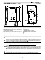
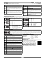
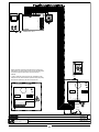
Affinche qualsiasi modifica alle impostazioni dei dip switch del
videocitofono o del posto esterno venga riconosciuta dal sistema,
è necessario togliere l'alimentazione di rete all'impianto e
restituirla.
In order to make the system recognize any modification of the
videophone's and outdoor station's dip-switch setting temporarily
disconnect the system from the mains and reconnect
Videx Electronics S.p.A.
Via del Lavoro 1, 63020 Monte Giberto (AP)
Phone: +39 0734 631669 - Fax +39 0734 631669
www.videx.it - [email protected]
Autore:
Data modifica:
Data creazione:Title:
Notes:
Titolo:
Note:
Cod.File:
Foglio
/11
Marco Rongoni
vk4k62h-002.dw
g
23/10/2015
18/11/2015
12345678 12
ON
Address N.
ON
+V
_
1
2
V1
SB
LD
2A
3A
4A
SW2
SW1
LB
V2
5A
1 Ext.1
Art.6256

66251130 - V2.0 - 31/05/18
- 11 -
Videx Electronics S.p.A.
Via del Lavoro 1, 63020 Monte Giberto (AP)
Phone: +39 0734 631669 - Fax +39 0734 631669
www.videx.it - [email protected]
Autore:
Data modifica:
Data creazione:Title:
Notes:
Titolo:
Note:
Cod.File:
Foglio
/11
Marco Rongoni
vk8k62h-002.dw
g
17/11/2015
17/11/2015
Local Bell
Push to
Exit
Door
Monitor
Art.8833-1
Using Electric Lock 12Vdc 0.3A Max
Con serratura elettrica 12Vdc 0.3A Max
Art.8833-1
In caso di modifica alle impostazioni dei dip switch del
videocitofono o del posto esterno, togliere temporaneamente
l'alimentazione di rete.
In order to make the system recognize any modification of the
videophone's and outdoor station's dip-switch setting, temporarily
disconnect the system from the mains and reconnect
12345678 12
ON
Address N.
ON
+V
_
1
2
V1
SB
LD
2A
3A
4A
SW2
SW1
LB
V2
5A
1 Ext. 1
Art.6256

66251130 - V2.0 - 31/05/18
- 12 -
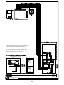
Using Electric Lock 12Vdc 0.3A Max
Con serratura elettrica 12Vdc 0.3A Max
43
21
ON
J1
VR4KAMK-1
Art.140
J2
Videx Electronics S.p.A.
Via del Lavoro 1, 63846 Monte Giberto (FM)
Phone: +39 0734 631669 - Fax +39 0734 631669
www.videx.it - [email protected]
Autore:
Data modifica:
Data creazione:Title:
Notes:
Titolo:
Note:
Cod.File:
Foglio
/11
Marco Rongoni
vrvk62h-001.dw
g
22/10/2015
01/12/2015
Push to
Exit
Affinche qualsiasi modifica alle impostazioni dei dip switch del
videocitofono o del posto esterno venga riconosciuta dal sistema,
è necessario togliere l'alimentazione di rete all'impianto e
restituirla.
In order to make the system recognize any modification of the
videophone's and outdoor station's dip-switch setting temporarily
disconnect the system from the mains and reconnect
432
1
ON
J1
VR4KAMK-1
Art.140
J2
Local Bell
Coax
NC
SL
ON
Art.VR4KCM
12345678 12
ON
Address N.
ON
+V
_
1
2
V1
SB
LD
2A
3A
4A
SW2
SW1
LB
V2
5A
1 Ext. 1
Art.6256
1

66251130 - V2.0 - 31/05/18
- 13 -
Videx Electronics S.p.A.
Via del Lavoro 1, 63020 Monte Giberto (AP)
Phone: +39 0734 631669 - Fax +39 0734 631669
www.videx.it - [email protected]
Autore:
Data modifica:
Data creazione:Title:
Notes:
Titolo:
Note:
Cod.File:
Foglio
/11
Marco Rongoni
vk4k62h-012.dw
g
17/11/2015
18/11/2015
1
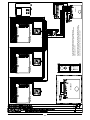
Art.4833-1
Using Electric Lock 12Vdc 0.3A Max
Con serratura elettrica 12Vdc 0.3A Max
1
Art.4833-1D
Push
to
Exit
1
Affinche qualsiasi modifica alle impostazioni dei dip switch del
videocitofono o del posto esterno venga riconosciuta dal sistema,
è necessario togliere l'alimentazione di rete all'impianto e
restituirla.
In order to make the system recognize any modification of the
videophone's and outdoor station's dip-switch setting temporarily
disconnect the system from the mains and reconnect
Local Bell
Local Bell
1 Ext. 2
Art.6256
1 Ext. 1
Art.6256

66251130 - V2.0 - 31/05/18
- 14 -
11
Marco Rongoni
vk8k62h-008.dw
g
01/12/2015
01/12/2015
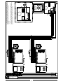
Using Electric Lock 12Vdc 0.3A Max
Con serratura elettrica 12Vdc 0.3A Max
Art.8833-1
In caso di modifica alle impostazioni dei dip switch del
videocitofono o del posto esterno, togliere temporaneamente
l'alimentazione di rete.
In order to make the system recognize any modification of the
videophone's and outdoor station's dip-switch setting, temporarily
disconnect the system from the mains and reconnect
Push to
Exit
Art.8833-1
+
Art.8800
12345678 12
ON
Address N.
ON
+V
_
1
2
V1
SB
LD
2A
3A
4A
SW2
SW1
LB
V2
5A
1 Ext. 1
Art.6256
12345678 12
ON
Address N.
ON
+V
_
1
2
V1
SB
LD
2A
3A
4A
SW2
SW1
LB
V2
5A
1 Ext. 2
Art.6256
12345678 12
ON
Address N.
ON
+V
_
1
2
V1
SB
LD
2A
3A
4A
SW2
SW1
LB
V2
5A
1 Ext. 3
Art.6256

66251130 - V2.0 - 31/05/18
- 15 -

MANUFACTURER
FABBRICANTE
FABRICANT
FABRICANTE
FABRIKANT
VIDEX ELECTRONICS S.P.A.
Via del Lavoro, 1
63846 Monte Giberto (FM) Italy
Tel (+39) 0734 631669
Fax (+39) 0734 632475
www.videx.it - inf[email protected]
CUSTOMER SUPPORT
SUPPORTO CLIENTI
SUPPORTS CLIENTS
ATENCIÓN AL CLIENTE
KLANTENDIENST
VIDEX ELECTRONICS S.P.A.
www.videx.it - technical@videx.it
Tel: +39 0734-631669
Fax: +39 0734-632475
UK Customers only:
VIDEX SECURITY LTD
www.videxuk.com
Tech Line: 0191 224 3174
Fax: 0191 224 1559
Main UK oce:
VIDEX SECURITY LTD
1 Osprey Trinity Park
Trinity Way
LONDON E4 8TD
Phone: (+44) 0870 300 1240
Fax: (+44) 020 8523 5825
www.videxuk.com
Northern UK oce:
VIDEX SECURITY LTD
Unit 4-7
Chillingham Industrial Estate
Chapman Street
NEWCASTLE UPON TYNE - NE6 2XX
Tech Line: (+44) 0191 224 3174
Phone: (+44) 0870 300 1240
Fax: (+44) 0191 224 1559
Greece oce:
VIDEX HELLAS Electronics
48 Filolaou Str.
11633 ATHENS
Phone: (+30) 210 7521028
(+30) 210 7521998
Fax: (+30) 210 7560712
www.videx.gr
Danish oce:
VIDEX DANMARK
Hammershusgade 15
DK-2100 COPENHAGEN
Phone: (+45) 39 29 80 00
Fax: (+45) 39 27 77 75
www.videx.dk
Benelux oce:
NESTOR COMPANY NV
E3 laan, 93
B-9800 Deinze
Phone: (+32) 9 380 40 20
Fax: (+32) 9 380 40 25
www.videx.be
Dutch oce:
NESTOR COMPANY BV
Business Center Twente (BCT)
Grotestraat, 64
NL-7622 GM Borne
www.videxintercom.nl
info@videxintercom.nl
El producto lleva la marca CE que demuestra su conformidad y puede ser
distribuido en todos los estados miembros de la unión europea UE.
Este producto cumple con las Directivas Europeas 2014/30/EU (EMC);
2014/35/EU (LVD); 2011/65/EU (RoHS): marca CE 93/68/EEC.
Het product heeft de CE-markering om de conformiteit ervan aan te tonen en
is bestemd voor distributie binnen de lidstaten van de EU zonder beperkin-
gen. Dit product volgt de bepalingen van de Europese Richtlijnen 2014/30/EU
(EMC); 2014/35/EU (LVD); 2011/65/EU (RoHS): CE-markering 93/68/EEG.
Le produit est marqué CE à preuve de sa conformité et peut être distribué
librement à l’intérieur des pays membres de l’union européenne EU.
Ce produit est conforme aux directives européennes 2014/30/EU (EMC) ;
2014/35/EU (LVD) ; 2011/65/EU (RoHS): marquage CE 93/68/EEC.
The product is CE marked demonstrating its conformity and is for distribution
within all member states of the EU with no restrictions. This product follows
the provisions of the European Directives 2014/30/EU (EMC); 2014/35/EU
(LVD); 2011/65/EU (RoHS): CE marking 93/68/EEC.
Il prodotto è marchiato CE a dimostrazione della sua conformità e può essere
distribuito liberamente all’interno dei paesi membri dell’Unione Europea UE.
Questo prodotto è conforme alle direttive Europee: 2014/30/UE (EMC);
2014/35/UE (LVD); 2011/65/UE (RoHS): marcatura CE 93/68/EEC.
-
 1
1
-
 2
2
-
 3
3
-
 4
4
-
 5
5
-
 6
6
-
 7
7
-
 8
8
-
 9
9
-
 10
10
-
 11
11
-
 12
12
-
 13
13
-
 14
14
-
 15
15
-
 16
16


Videx 6200 Series Manuale utente
- Categoria
- Impianti citofonici
- Tipo
- Manuale utente
- Questo manuale è adatto anche per
in altre lingue
- English: Videx 6200 Series User manual
- français: Videx 6200 Series Manuel utilisateur
Documenti correlati
-
Videx 6700 Series Manuale utente
-
Videx Security ESVK (4000 Series) Manuale del proprietario
-
-
-
Videx 2313 Manuale utente
-
-
-
-
-
Videx Security 3141 Manuale del proprietario
Altri documenti
-
-
-
-
-
Smeg S45MFX Manuale utente
-
 TAMUZ KVM 1750W Istruzioni per l'uso
-
Comelit COLOR BRAVO 8184 Technical Manual
-
-
 Videovox Pro GB Series Guida utente
-
 Nuface Trinity/PRO Manuale utente


