

Lexicon Part #070-13227 Rev 1 Printed in the United States of America
Save these instructions for later use.
Follow all instructions and warnings marked on the unit.
Always use with the correct line voltage. Refer to the manufacturer's operating instructions for power requirements. Be advised that different operating voltages
may require the use of a different line cord and/or attachment plug.
Do not install the unit in an unventilated rack, or directly above heat producing equipment such as power amplifiers. Observe the maximum ambient operating
temperature listed in the product specification.
Slots and opening on the case are provided for ventilation; to ensure reliable operation and prevent it from overheating, these openings must not be blocked or
covered. Never push objects of any kind through any of the ventilation slots. Never spill a liquid of any kind on the unit.
Never attach audio power amplifier outputs directly to any of the unit's connectors.
To prevent shock or fire hazard, do not expose the unit to rain or moisture, or operate it where it will be exposed to water.
Do not attempt to operate the unit if it has been dropped, damaged, exposed to liquids, or if it exhibits a distinct change in performance indicating the need for
service.
This unit should only be opened by qualified service personnel. Removing covers will expose you to hazardous voltages.
Important Safety Instructions
CAUTION
RISK OF ELECTRIC SHOCK
DO NOT OPEN
This triangle, which appears on your component,
alerts you to important operating and maintenance
instructions in this accompanying literature.
This triangle, which appears on your component,
alerts you to the presence of uninsulated, dangerous
voltage inside the enclosure... voltage that may be
sufficient to constitute a risk of shock.
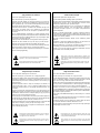
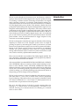
Outdoor Antenna Grounding
If an outside antenna is connected to the receiver, be sure the antenna system is grounded so as to
provide some protection against voltage surges and built-up static charges. Section 810 of the
National Electrical Code, ANSI/NFPA No. 70-1984, provides information with respect to proper
grounding of the mast and supporting structure, grounding of the lead-in wire to an antenna-discharge
unit, size of grounding conductors, location of antenna-discharge unit, connection to grounding
electrodes, and requirements for the grounding electrode. See figure below.
Power Lines An outside antenna should be located away from power lines.
Power Service Grounding
Electrode System
(NEC Art 250, Part H)
Antenna Lead-in
Wire
Antenna Discharge
Unit (NEC Section
810-20)
Grounding Conductors
(NEC Section 810-21)
Ground Clamps
NEC — National Electrical Code
Electric
Service
Equipment
Ground
Clamp
Le présent appareil numérique n'émet pas de bruits radioélectriques dépassant les limites applicables aux appareils numériques de la class B prescrites dans
le Règlement sur le brouillage radioélectrique édicté par le ministère des Communications du Canada.
Adhere to all warnings on the unit and in the operating instructions.
Take precautions not to defeat the grounding or polarization of the unit's power cord.
Do not overload wall outlet, extension cords or integral convenience receptacles, as this can result in a risk of fire or electrical shock.
Route power supply cords so that they are not likely to be walked on or pinched by items placed on or against them, paying particular attention to cords at plugs,
conveneince receptacles, and the point at which they exit from the unit.
The unit should be cleaned only as recommended by the manufacturer.
This equipment generates and uses radio frequency energy and if not installed and used properly, that is, in strict accordance with the manufacturer's instructions,
may cause interference to radio and television reception. It has been type tested and found to comply with the limits for a Class B computing device in accordance
with the specifications in Subpart B of Part 15 of FCC Rules, which are designated to provide reasonable protection against such interference in a residential
installation. However, there is no guarantee that interference will not occur in a particular installation. If this equipment does cause interference to radio or television
reception, which can be determined by turning the equipment OFF and ON, the user is encouraged to try to correct the interference by one or more of the following
measures:
Reorient the receiving antenna
Relocate the computer with respect to the receiver
Move the computer away from the receiver
Plug the computer into a different outlet so that the computer and receiver are on different branch circuits.
If necessary, the user should consult the dealer or an experienced radio/television technician for additional suggestions. The user may find the following booklet
prepared by the Federal Communications Commission helpful: "How to identify and Resolve Radio/TV Interference Problems." This booklet is available from the
U.S. Government Printing Office, Washington, DC 20402, Stock No. 004-000-00345-4.
Communications Notice
Lexicon, Inc.• 3 Oak Park • Bedford MA • 01730-1441 USA • Tel: 781-280-0300 • Fax: 781- 280-0490
e-mail: [email protected] • www.lexicon.com
Copyright ©1999 Lexicon. Inc. All Rights Reserved. U.S. Patent numbers 4,862,502; 5,136,650 and 5,796,844; other patents pending on the DC-2.
Acknowledgements
Manufactured under license from Dolby Laboratories. "Dolby", "Pro Logic", "AC-3",and the double-D symbol are trademarks of Dolby Laboratories Confidential
Unpublished Works. ©1992-1997 Dolby Laboratories, Inc. All rights reserved.
Manufactured under license from Lucasfilm Ltd. U.S. patent numbers 5,043,970; 5,189,703; and 5,222,059. Foreign patents pending. "Lucasfilm" and "THX"
are trademarks of Lucasfilm Ltd.
Manufactured under license from Digital Theatre Systems, Inc. U.S. Patent number 5,451, 942 and other world-wide patents issued and pending. "DTS" and
"DTS Digital Surround" are trademarks of Digital Theatre Systems, Inc. ©1996 Digital Theatre Systems, Inc. All rights reserved.
©Lucasfilm Ltd. & TM. All Rights Reserved. Surround EX is a jointly developed technology of THX and Dolby Labs, Inc., and is a trademark of Dolby. Used under
authorization.
"Logic 7" and "Auto-Azimuth" are trademarks of Lexicon, Inc.

Dansk
Vigtig information om sikkerhed
Gem denne vejledning til senere brug.
Følg alle anvisninger og advarsler på apparatet.
Apparatet skal altid tilsluttes den korrekte spænding. Der henvises til
brugsanvisningen, der indeholder specifikationer for strømforsyning. Der
gøres opmærksom på, at ved varierende driftsspændinger kan det blive
nødvendigt at bruge andre lednings- og/eller stiktyper.
Apparatet må ikke monteres i et kabinet uden ventilation eller lige over
andet udstyr, der udvikler varme, f.eks. forstærkere. Den maksimale
omgivelsestemperatur ved drift, der står opført i specifikationerne, skal
overholdes.
Der er ventilationsåbninger i kabinettet. For at sikre apparatets drift og
hindre overophedning må disse åbninger ikke blokeres eller tildækkes. Stik
aldrig noget ind igennem ventilationsåbningerne, og pas på aldrig at spilde
nogen form for væske på apparatet.
Udgangsstik fra audioforstærkere må aldrig sættes direkte i apparatet.
Apparatet må ikke udsættes for regn eller fugt og må ikke bruges i
nærheden af vand for at undgå risiko for elektrisk stød og brand.
Apparatet må aldrig bruges, hvis det er blevet stødt, beskadiget eller vådt,
eller hvis ændringer i ydelsen tyder på, at det trænger til eftersyn.
Dette apparat må kun åbnes af fagfolk. Hvis dækslet tages af, udsættes
man for livsfarlig højspænding.
Denne mærkat på komponenten advarer om vigtig drifts- og
vedligeholdsinformation i den tilhørende litteratur.
Denne mærkat på komponenten advarer om uisoleret, farlig spænding
i apparatet ... høj nok til at give elektrisk stød.
Suomi
Tärkeitä turvallisuusohjeita
Säilytä nämä ohjeet tulevaa käyttöä varten.
Seuraa kaikkia yksikköön merkittyjä ohjeita ja varoituksia.
Käytä aina oikeaa verkkojännitettä. Tehovaatimukset selviävät valmistajan
käyttöohjeista. Huomaa, että eri käyttöjännitteet saattavat vaatia
toisenlaisen verkkojohdon ja/tai -pistokkeen käytön.
Älä asenna yksikköä telineeseen jossa ei ole tuuletusta, tai välittömästi
lämpöä tuottavien laitteiden, esim. tehovahvistimien, yläpuolelle.
Ympäristön lämpötila käytössä ei saa ylittää tuotespesifikaation
maksimilämpötilaa.
Kotelo on varustettu tuuletusreiillä ja -aukoilla. Luotettavan toiminnan
varmistamiseksi ja ylilämpenemisen välttämiseksi näitä aukkoja ei saa
sulkea tai peittää. Mitään esineitä ei saa työntää tuuletusaukkoihin. Mitään
nesteitä ei saa kaataa yksikköön.
Älä kytke audiotehovahvistimen lähtöjä suoraan mihinkään yksikön
liittimeen.
Sähköiskun ja palovaaran välttämiseksi yksikkö ei saa olla sateessa tai
kosteassa, eikä sitä saa käyttää märässä ympäristössä.
Älä käytä yksikköä jos se on pudonnut, vaurioitunut, kostunut, tai jos sen
suorituskyky on huomattavasti muuttunut, mikä vaatii huoltoa.
Yksikön saa avata vain laitteeseen perehtynyt huoltohenkilö. Kansien
poisto altistaa sinut vaarallisille jännitteille.
Tämä kolmio, joka esiintyy komponentissasi, kertoo sinulle, että
tässä tuotedokumentoinnissa esiintyy tärkeitä käyttö- ja ylläpito-
ohjeita.
Tämä kolmio, joka esiintyy komponentissasi, varoittaa sinua
eristämättömän vaarallisen jännitteen esiintymisestä yksikön sisällä.
Tämä jännite saattaa olla riittävän korkea aiheuttamaan
sähköiskuvaaran.
Norsk
Viktig informasjon om sikkerhet
Ta vare på denne veiledningen for senere bruk.
Følg alle anvisningene og advarslene som er angitt på apparatet.
Apparatet skal alltid anvendes med korrekt spenning. Produktbeskrivelsen
inneholder spesifikasjoner for strømkrav. Vær oppmerksom på at det ved
ulike driftsspenninger kan være nødvendig å bruke en annen ledning- og/
eller støpseltype.
Apparatet skal ikke monteres i skap uten ventilasjon, eller direkte over
varmeproduserende utstyr, som for eksempel kraftforsterkere. Den
maksimale romtemperaturen som står oppgitt i produktbeskrivelsen, skal
overholdes.
Apparatet er utstyrt med ventilasjonsåpninger. For at apparatet skal være
pålitelig i bruk og ikke overopphetes, må disse åpningene ikke blokkeres
eller tildekkes. Stikk aldri noe inn i ventilasjonsåpningene, og pass på at det
aldri søles noen form for væske på apparatet.
Utgangsplugger fra audioforsterkere skal aldri koples direkte til apparatet.
Unngå brannfare og elektrisk støt ved å sørge for at apparatet ikke utsettes
for regn eller fuktighet og ikke anvendes i nærheten av vann.
Apparatet skal ikke brukes hvis det har blitt utsatt for støt, er skadet eller blitt
vått, eller hvis endringer i ytelsen tyder på at det trenger service.
Dette apparatet skal kun åpnes av fagfolk. Hvis dekselet fjernes, utsettes
man for livsfarlig høyspenning.
Komponenten er merket med denne trekanten, som er en advarsel
om at det finnes uisolert, farlig spenning inne i kabinettet ... høy nok
til å utgjøre en fare for elektrisk støt.
Svenska
Viktiga säkerhetsföreskrifter
Spara dessa föreskrifter för framtida bruk.
Följ alla anvisningar och varningar som anges på enheten.
Använd alltid rätt nätspänning. Se tillverkarens bruksanvisningar för infor-
mation om effektkrav. Märkväl, att andra matningsspänningar eventuellt
kräver att en annan typs nätsladd och/eller kontakt används.
Installera inte enheten i ett oventilerat stativ, eller direkt ovanför utrustningar
som avger värme, t ex effektförstärkare. Se till att omgivningens temperatur
vid drift inte överskrider det angivna värdet i produktspecifikationen.
Behållaren är försedd med hål och öppningar för ventilering. För att
garantera tillförlitlig funktion och förhindra överhettning får dessa öppningar
inte blockeras eller täckas. Inga föremål får skuffas in genom ventilationshålen.
Inga vätskor får spillas på enheten.
Anslut aldrig audioeffektförstärkarutgångar direkt till någon av enhetens
kontakter.
För att undvika elstöt eller brandfara får enheten inte utsättas för regn eller
fukt, eller användas på ställen där den blir våt.
Använd inte enheten om den har fallit i golvet, skadats, blivit våt, eller om
dess prestanda förändrats märkbart, vilket kräver service.
Enheten får öppnas endast av behörig servicepersonal. Farliga spänningar
blir tillgängliga när locken tas bort.
Denna triangel, som visas på din komponent, varnar dig om en
oisolerad farlig spänning inne i enheten. Denna spänning är eventuellt
så hög att fara för elstöt föreligger.
Komponenten er merket med denne trekanten, som betyr at den
tilhørende litteraturen inneholder viktige opplysninger om drift og
vedlikehold.
Denna triangel, som visas på din komponent, anger att viktiga
bruksanvisningar och serviceanvisningar ingår i dokumentationen i
fråga.

Dieses Dreieck auf Ihrem Apparat bedeutet daß wichtige Betriebs-
und Wartungsanweisungen in der mitgelieferten Dokumentation zu
finden sind.
Dieses Dreieck auf Ihrem Apparat warnt Sie vor nicht-isolierter,
gefährlicher Spannung im Gehäuse ... stark genug um eine
Berührungsgefahr darzustellen.
Deutsch
Wichtige Sicherheitsanweisungen
Heben Sie sich diese Sicherheitsanweisungen auch für später auf.
Befolgen Sie alle auf der Vorrichtung stehenden Anweisungen und Warnungen.
Immer nur mit der richtigen Spannung verwenden! Die Gebrauchsanweisungen
des Herstellers informieren Sie über die elektrischen Anforderungen.
Vergessen Sie nicht daß bei verschiedenen Betriebsspannungen ggf. auch
verschiedene Leitungskabel und/oder Verbindungsstecker zu verwenden
sind.
Stellen Sie die Vorrichtung nicht in ein unbelüftetes Gestell oder unmittelbar
über wärmeerzeugende Geräte wie z.B. Tonverstärker. Halten Sie die in den
Produktspezifikationen angegebene maximale Umgebungstemperatur bei
Betrieb ein.
Schlitze und Öffnungen im Gehäuse dienen der Belüfung; um verläßlichen
Betrieb sicherzustellen und Überheizen zu vermeiden dürfen diese Öffnungen
nich verstopft oder abgedeckt werden. Stecken Sie nie irgend einen
Gegenstand durch die Belüftungsschlitze. Vergießen Sie keine Flüssigkeiten
auf den Apparat.
Schließen Sie nie Tonverstärker unmittelbar an einen Anschluß des Apparates
an.
Um elektrischen Schlag oder Feuer zu vermeiden, setzen Sie den Apparat
weder Regen noch Feuchtigkeit aus und betreiben Sie ihn nicht dort wo
Wasser eindringen könnte.
Versuchen Sie nicht den Apparat zu betreiben falls er fallen gelassen,
beschädigt, oder Flüssigkeiten ausgesetzt wurde, oder falls sich seine
Arbeitsweise derart ändert daß daraus ein Bedarf nach Raparatur zu schließen
ist.
Dieser Apparat sollte nur von qualifizierten Fachleuten geöffnet werden. Das
Abnehmen von Abdeckungen setzt Sie gefährlichen Spannungen aus.
Español
Instrucciones importantes de seguridad
Guarde esta instrucciones para uso posterior.
Utilice siempre el voltaje correcto. Diríjase a las instrucciones de operación
del fabricante para obtener las especificaciones de potencia. Esté al tanto
de que voltajes de operación distintos requieren el uso de cables y/o
enchufes distintos.
No instale esta unidad en un estante sin ventilación, ni tampoco directamente
encima de equipos que generen calor tales como amplificadores de
potencia. Fíjese en las temperaturas ambientales máximas de operación
que se mencionan en las especificaciones del producto.
Las aperturas y ranuras del chasis sirven para proveer la ventilación
necesaria para operar la unidad con seguridad y para prevenir
sobrecalentamiento, y por lo tanto no pueden ser obstruidas o cubiertas. No
introduzca objetos de ningún tipo a través de las ranuras de ventilación, y
nunca deje caer ningún líquido sobre la unidad.
Nunca conecte ningún tipo de salida de amplificadores de sonido directamente
a los conectores de la unidad.
Para prevenir descargas eléctricas o incendios, mantenga la unidad alejada
de la lluvia, humedad o cualquier lugar en el que pueda entrar en contacto
con agua.
No trate de hacer funcionar la unidad si se ha caído, está dañada, ha entrado
en contacto con líquidos, o si nota cualquier cambio brusco en su
funcionamiento que indique la necesidad de hacerle un servicio de
mantenimiento.
Esta unidad deberá ser abierta únicamente por personal calificado. Si usted
quita las coberturas se expondrá a voltajes peligrosos.
Este triángulo que aparece en su componente lo alerta sobre las
instrucciones de operación y mantenimiento importantes que están
en los materiales de lectura que se incluyen.
Este triángulo que aparece en su componente le advierte sobre la
existencia dentro del chasis de voltajes peligrosos sin aislantes ...
voltajes que son lo suficientemente grandes como para causar
electrocución.
Français
Instructions de Sûreté Importantes
Gardez ces instructions pour réference future.
Observez toutes les instructions et tous les avertissements marqués sur
l’appareil.
Branchez uniquements sur un réseau de tension indiquée. Consultez le
manuel d’instruction du fabriquant pour les spécifications de courant.
N’oubliez pas que différentes tensions peuvent nécessiter l’utilisation de
cables et/ou de fiches de connexion différents.
N’installez pas l’appareil en un compartiment non-aéré ou directement au-
dessus d’équipements générateurs de chaleur, tels qu’amplificateurs de
courants, etc. Ne dépassez pas la température ambiante maximale de
fonctionnement indiquée dans les spécifications du produit.
Des fentes et ouvertures sont prévues dans le boîtier pour l’aération; Pour
assurer le bon fonctionnement et pour prévenir l’échauffement, ces ouvertures
ne doivent pas être couvertes ou bloquées. N’insérez pas d’objets dans les
fentes d’aération. Empêchez tout liquide de se répandre sur l’appareil.
Ne connectez jamais d’amplificateurs audio directement aux connecteurs
de l’appareil.
Pour empêcher les chocs électriques et le danger d’incendie, évitez d’exposer
l’appareil à la pluie ou à l’humidité, et ne le mettez pas en marche en un
endroit où il serait exposé aux éclaboussures d’eau.
N’essayez pas de faire fonctionner l’appareil s’il est tombé à terre, a été
endommangé, exposé à un liquide, ou si vous observez des différences
nettes dans son fonctionnement, indiquant la nécessité de réparations.
Cet appareil ne doit être ouvert que par un personnel de service qualifié. En
enlevant les couvercles vous vous exposez à des tensions électriques
dangereuses.
Ce triangle sur sur votre appareil vous invite de suivre d’importantes
instructions d’utilisation et d’entretien dans la documentation livrée
avec le produit.
Ce triangle, sur votre appareil vous avertit de la présence de tension
dangereuse, non-isolée à l’intérieur du boîtier...une tension suffisante
pour représenter un danger d’électrocution.
Italiano
Importanti norme di sicurezza
Conservare le presenti norme per l’utilizzo futuro.
Osservare tutte le istruzioni e le avvertenze apposte sull’unità.
Utilizzare esclusivamente con la tensione di rete corretta. Consultare le
istruzioni operative fornite dal fabbricante per i dati riguardanti la tensione e
l’assorbimento di corrente. Potrebbe essere necessario l’uso di cavi di rete
e/o di spine diverse a seconda della tensione utilizzata.
Non installare l’unità in uno scaffale privo di ventilazione oppure direttamente
sopra una fonte di calore, come, ad esempio, un amplificatore. Non superare
la temperatura ambientale massima di funzionamento riportata nei dati
tecnici del prodotto.
Le fessure e le altre aperture nella scatola servono alla ventilazione. Per un
funzionamento affidabile, e per evitare un eventuale surriscaldamento,
queste aperture non vanno ostruite o coperte in nessun modo. Evitare in tutti
i casi di inserire oggetti di qualsiasi genere attraverso le fessure di ventilazione.
Non versare mai del liquido di nessun tipo sull’unità.
Evitare sempre di collegare le uscite dell’amplificatore audio direttamente ai
connettori dell’unità.
Per prevenire il pericolo di folgorazione e di incendio non esporre l’unità alla
pioggia o ad un’umidità eccessiva; evitare di adoperare l’unità dove potrebbe
entrare in contatto con acqua.
Evitare di adoperare l’unità se la stessa è stata urtata violentemente, se ha
subito un danno, se è stata esposta ad un liquido o in caso di un evidente
cambiamento delle prestazioni che indichi la necessità di un intervento di
assistenza tecnica.
Ogni intervento sull’unità va eseguito esclusivamente da personale qualificato.
La rimozione della copertura comporta l’esposizione al pericolo di
folgorazione.
Il presente triangolo impresso sul componente avverte l’utente della
presenza nella documentazione allegata di importanti istruzioni relative
al funzionamento ed alla manutenzione.
Il presente triangolo impresso sul componente avverte della presenza
di tensioni pericolose non isolate all’interno della copertura... tali
tensioni rappresentano un pericolo di folgorazione

Contents
DC-2 Digital Controller
Introduction
1 Installation
Controls and Indicators .....................................................1
The Front Panel ...........................................................1
The Rear Panel............................................................2
The Remote Control ....................................................3
Alternate Remote Control Functions Using the
Shift and Record/Zone 2 buttons
Conection ..........................................................................6
Location Considerations ..............................................6
AC Connections...........................................................6
Wiring Considerations..................................................7
Audio/Video Cables • Speaker Conncetions
Audio/Video Connections
DC-2 Connections .......................................................8
Video Connections • Digital Audio Connections
"AC-3 Ready" Laser Disc and LD/DVD Players
2 System Configuration
Restore Factory Defaults.................................................11
Equalization.....................................................................11
Bass and Treble Level • Tilt • Loudness
Display Adjustment..........................................................13
The Video On-Screen Display
Input Configuration ..........................................................15
Input Gain (Analog Inputs Only) • Input Level Meters
Input Name • Input Effect "FX" Assignment
FX Format .......................................................................17
Automatic • PCM Only • AC-3 Only • DTS Only
Audio In ...........................................................................20
Analog • Coax-1-5 and Optical-1-3 (Digital Audio
Inputs)
Video In ...........................................................................20
Record/Zone 2.................................................................21
Record/Zone 2 Controls • PGM Trigger Assignment
Speaker Configuration.....................................................23
Custom Configuration • THX Configuration
Surround EX Configuration
Setting Output Levels ......................................................25
Note on External Noise Calibration • Subwoofer
Peak Limiter • Mute Level • Power On Volume
Zone 2 Power On Volume
Setting Listener Position..................................................28
Speaker Distance • A/V Sync Delay • Calibrate
Panorama • L/R Balance • Zone 2 Balance
Customization..................................................................32
Locking Settings • Assign Custom Name

Lexicon
Using DC-2 Effects ..........................................................33
Restoring the original parameter values of an Effect
Naming your custom Effect • Restoring the original
Effect Name • Listening to only the DC-2 Effect
Front/Back Fader
3 PCM Effects and Parameters
Panorama ........................................................................35
Nightclub .........................................................................35
Concert Hall.....................................................................36
Church .............................................................................36
Cathedral .........................................................................36
Party ................................................................................37
2-Channel ........................................................................37
Music Surround ...............................................................37
Music Logic .....................................................................38
Logic 7 .............................................................................38
TV Matrix .........................................................................39
Pro Logic .........................................................................39
THX Cinema ....................................................................39
Mono Logic ......................................................................40
PCM Effect Parameters...................................................40
4 AC-3 Effects and Parameters
AC-3 Status Display ........................................................45
5.1 2-Channel ..................................................................46
5.1 Music .........................................................................46
5.1 Logic 7.......................................................................47
Dolby Digital ....................................................................47
THX 5.1 (Including Surround EX) ....................................48
AC-3 Effect Parameters ..................................................48
5 DTS Effects and Parameters
DTS 2-Channel................................................................51
DTS Music.......................................................................51
DTS Logic 7.....................................................................52
DTS Film .........................................................................52
DTS THX (Including Surround EX)..................................53
DTS Effect Parameters ...................................................53
6 Troubleshooting
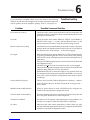
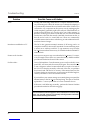
Problems and Solutions ..................................................55
Routine Maintenance ......................................................57
Restoring Defaults ...........................................................57
7 Specifications
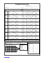
Installation Worksheet

Introduction
The DC-2 can be thought of as four units in one. At its heart is a reference-
quality 8-channel music and film digital audio computer capable of creating
or recreating a limitless amount of listening environments. This digital
audio computer is mated to an 8-channel, 24-bit Digital-to-Analog con-
verter that rivals the most exotic and costly stand-alone devices. To harness
all of this digital audio power, the DC-2 also includes a built-in line-level
preamplifier with 8 analog audio inputs and 8 digital audio inputs for easy
integration with multiple source components. Since many of these source
components are also capable of outputting high quality video signals, the
DC-2 includes a high-quality composite and S-video switcher. The DC-2
also includes provisions for adding a digital output, and a second RS-232
port as well as three expansion ports for future enhancements. The back
panel includes a bare wire block terminal for trigger outputs for easy
connection to associated equipment.
The DC-2 is designed to satisfy the most rigorous demands, while retaining
simplicity for casual use as well. Using the system can be as simple as
pressing an input key and turning the volume up and down. Less-used
functions are organized into a simple on-screen menu system and “hidden”
buttons on the remote control. Controls are provided to accommodate
virtually any system configuration and to allow for varying recording,
mixing, and transmission styles, as well as for system control from a second
zone, and for control by sophisticated automation systems.
Three versions of the DC-2 are available: THX, Dolby Digital, and DTS. The
unit is internally-configurable so upgrades can be progressively added to
include all the features of the DTS version.
All versions of the DC-2 include NIGHTCLUB, CONCERT HALL, CHURCH,
and CATHEDRAL effects for creating an ideal custom listening environ-
ment as well as MUSIC LOGIC and MUSIC SURROUND which offer
ambience extraction. As these programs use the same Lexicon technology
used by the overwhelming majority of professionals for adding ambience
to their recordings, you will find playback greatly enhanced by the DC-2,
transporting you more deeply into the performance.
The DC-2 also recreates 5.1 channel soundtracks with stunning accuracy,
and takes them to a new level of realism with Lexicon’s proprietary
Logic 7 technology. These effects allow you to expand 5.1 channel as well as
two channel soundtracks for 7.1 and virtual 7.1 channel playback for an
increased sense of spaciousness and envelopment.
The AC-3 and DTS versions of the DC-2 provide separate effects for
listening to 5.1 channel music and down-mixing 5.1 channels to two
channels, allowing you to fine-tune the DC-2 for listening to 5.1 channel
music or music videos.

Lexicon
Using the
Documentation Because the DC-2 is designed to be customized for your system and your
listening space, the information required for installation is extensive.
The Owner's Manual is designed to assist you in installing, calibrating and
operating the DC-2. It should be used in conjunction with the remote control
when configuring the system to perform optimally in your environment.
This manual was written with the underlying assumption that the installer
is familiar with audio/video system installation. An Installation
Worksheet is provided at the end of this manual for documentation of the
settings arrived at during the calibration procedure.
Glossary of Terms
The DC-2 can be easily integrated with the various types of loudspeaker
systems currently available, including those that are THX certified. By
adhering to the rigorous THX Ultra specification, the DC-2 includes THX
enhancements for optimizing playback of matrix-encoded film soundtracks
as well as Surround EX for those recorded in the Dolby Digital and DTS
discrete formats. These enhancements ensure that film soundtracks, which
are typically mixed for the acoustics of large theaters, sound as the filmmak-
ers intended when played back in the relatively small environment of a
home theater.
Although the DC-2 performs very complex signal processing, a great deal
of effort has gone into making the technology behind the effects as transpar-
ent as possible to the user. To understand the overall organization of the
unit, it is helpful to define those few terms which are unique to the DC-2.
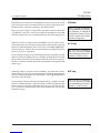
AC-3 FX The term AC-3 FX (Dolby Digital Effects) is used to describe all of
the effects which are compatible with Dolby Digital input signals. Any AC-
3-capable software and/or source components should be labeled with a
badge, similar to the one on the DC-2 front panel (AC-3 and DTS versions).
DTS FX The term DTS FX (Digital Surround Effects) is used to describe all
of the effects which are compatible with DTS Digital Surround input
signals. Any DTS-capable software and/or source components should be
labeled with a badge, similar to the one on the DC-2 front panel (AC-3 and
DTS versions).
Downmix describes the process of creating a two-channel output from a
multichannel (>2) signal. Downmixing is necessary to maintain compatibil-
ity between multichannel formats and devices such as Dolby Digital and
DTS, and two-channel formats and devices, such as stereo tape decks and
VCRs.

Effect An effect is a configuration that determines how the DC-2 will process
an input signal. The DC-2 can contain as many as 24 effects: Panorama,
Nightclub, Concert Hall, Church, Cathedral, Party, 2-Channel, Music Surround,
Music Logic, Logic 7, TV Matrix, Pro Logic, THX Cinema, Mono Logic, 5.1 2-
Channel, 5.1 Music, 5.1 Logic 7, Dolby Digital, THX 5.1, DTS 2-Channel, DTS
Music, DTS Logic 7, DTS Film and DTS THX 5.1.
Parameter Each Effect has a set of parameters (controls) that characterize it.
Parameter settings can be changed to customize each Effect for your room
and listening taste.
Effect Parameter values are stored/recalled with each Effect. Some examples
are: Subwoofer Level and Vocal Enhance
System parameter values are not associated with a particular Effect and their
values do not change when a new Effect is loaded. An example is: Speaker
Configuration.
PCM FX The term PCM FX (Pulse Code Modulation Effects) is used to
describe all of the effects which are compatible with two-channel input
signals (analog or digital).
Two-Channel We use the term two-channel rather than "stereo" because a
two-channel input can contain monaural, stereo or matrix-encoded stereo
sound depending on how it was mixed.

1
DC-2 Digital Controller
Installation
1
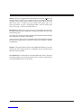
Controls and
Indicators
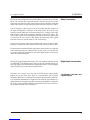
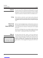
The Front Panel
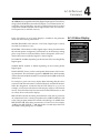
1. ON/OFF
ON/OFF alternately puts the
DC-2 into and out of standby.
Turning the DC-2 off with this
button (or with the remote)
deactivates the unit while
leaving power to the signal
processing circuitry to keep it
at optimum operating tem-
perature. Turning the DC-2
on with this button (or the
remote) will restore the previ-
ous operating state.
2. Input Selection
Pressing any of these but-
tons (VCR, DVD, V-DISC, TV,
AUX, CD, TUNER, TAPE)
selects the input for the main
zone, and lights a green LED.
6. MUTE
Attenuates the main audio
outputs, lights a red LED, and
displays a screen message
to indicate mute is engaged.
The attenuation level can be
set in the Setup: Output Lev-
els menu.
7. IR Receiver and LED
The IR receiver has an asso-
ciated activity LED that lights
green when valid IR signals
are received, and an LED that
lights red to indicate clipping
at the inputs. An IR input jack
is available on the rear panel
for receipt of hard-wired sig-
nals. The red LED remains
illuminated when the unit is
placed in standby.
8. Display
A 2x20 backlit LCD displays
the result of user action and
the current status. This dis-
play can be turned off with
the remote control.
9. VOLUME
Provides volume adjustment
of the main outputs. Screen
displays show a volume bar
and level in dB unless the
front panel display is turned
off with the remote control.
Installation
®
LEXICON DC-2
COPYRIGHT 1999
DC-2 Digital Controller
ON/OFF VCR DVD V-DISC TV AUX CD TUNER TAPE REC/ZONE 2 EFFECT 2-CHANNEL MUTE
25
87 9
346
1
3. REC/ZONE 2
Press and hold to activate
Zone 2 control with the On/
Off, Input Selector, Volume
and Mute buttons..
Some sources are blocked
because of the potential for
feedback loops. By default
these are TAPE and VCR. If
a blocked source is selected,
a message is displayed. This
source blocking can be
changed in the INPUT
CONFIG menu.
4. EFFECT
Displays the current effect,
then steps through the avail-
able effects.
5. 2-CHANNEL
Engages the appropriate 2-
Channel effect, and lights the
amber front panel LED.

Lexicon
2
Installation
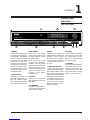
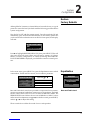
The Rear Panel
CAUTION: Never make or break any connections to the DC-2 with the
rear-panel power ON. Make sure any associated amplifiers are turned
off before turning this master power switch on or off.
1 AUDIO INPUTS
Eight stereo analog audio in-
puts are switched with corre-
sponding video inputs and fed
to the Monitor outputs. Inputs
are nominally labeled as origi-
nating from an audio tape
player, tuner, CD player, an
unspecified auxiliary source,
a TV tuner, a Laser or Video
Disc player, a DVD player,
and a VCR.
2 ZONE2 and RECORD
Each pair of stereo audio
outputs supplies the same
signal according to the
Record/Zone 2 input selec-
tion. Zone 2 output levels can
be controlled independently
for use with amplifiers and
speakers in another room.
Record can be expanded to
two outputs using standard
Y-connectors. Both outputs
are muted in Standby.
3 MAIN OUTPUTS
Three stereo amplifier out-
puts are provided for front,
side and rear speakers.
Single monaural outputs are
provided for the center
speaker and the subwoofer.
The audio outputs are muted
in Standby.
4 IR Input, PWR and
PGM TRIGGERS
The IR input is an 1/8" mono
phone jack connector for in-
put of IR data from any indus-
try-standard IR source. Data
is retransmitted by an IR LED
mounted near the front panel
IR receiver.
Two trigger outputs are pro-
vided on 4-pin removable
screw terminals, and a 5-pin
DIN connector, as shown in
the expanded illustration
above. The PWR trigger is
high when the DC-2 is on, low
in standby or when the unit is
off. The PGM trigger can be
enabled (high) or disabled
(low) for specific input selec-
tions in the Input Configura-
tion menu. High is indicated
by either +12VDC or +5VDC,
selectable via an internal
jumper. (Factory configura-
tion is +12V.)
5 VIDEO INPUTS and
OUTPUTS
Five video input sources are
provided. Video inputs are
selected based on selections
made in the INPUT CONFIG
menu and fed to the selected
monitor output jack. Record
output jacks can be selected
independently.
RCA (composite) and S-
video connectors are pro-
vided for monitor and record.
If an S-video input is used,
both S-video and composite
are available at each output.
If the video input is compos-
ite, only composite is avail-
able at each output. The
monitor output incorporates
the on-screen video overlay.
Unless RECORD is enabled,
the record output follows the
monitor output selection with-
out the on-screen display fea-
ture. Both outputs are off in
Standby.
6 S/PDIF INPUTS
Five coaxial RCA connectors
and three optical connectors
are provided for digital audio
inputs.
7 EXPANSION PORTS
Reserved for future upgrades.
8 RS 232
Serial port connector for au-
tomation and control systems.
9 Power On/Off
Master power switch discon-
nects the AC Mains. This
switch is intended to be left
On during regular use. When-
ever cables are connected or
disconnected, or when the
unit is not going to be used for
an extended period of time,
this switch should be set to
Off.
10 POWER
AC power connector: 3-wire,
10 Amp, IEC 320.
SERIAL NO.
TAPE TUNER
AUDIO
S-VIDEO
MAIN OUTPUTS S/PDIF INTPUTS
VIDEO
INPUT OUTPUT POWER
TRIGGERS
TRIGGERS
GND
PGMPWR
RS 232
IR IN
CD AUX TV V-DISC DVD VCR ZONE 2
L
R
L
R
1
3
2
4
L
R
L
R
L
R
MONITOR
RECORD REAR SIDE CENTER
SUBWOOFER
FRONT
DC-2
LEXICON, INC. ASSEMBLED IN U.S.A.
100-240V 50-60 Hz
R R
LISTED AUDIO
EQUIPMENT
7D77
E172268
C
PGM GND PWR
RISK OF ELECTRIC SHOCK
DO NOT OPEN
RISQUE DE CHOC ELECTRIQUE
NE PAS OUVRIR
CAUTION
ATTENTION
EXPANSION PORTS
ABC
S/PDIF OUT
5
123
1 32
5 6 7
410
9
8
TRIGGERS
TRIGGERS
GND
PGMPWR
IR IN
PGM GND PWR
4

3
DC-2 Digital Controller
Installation
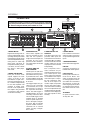
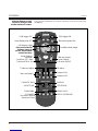
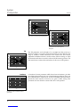
The Remote Control
Shift
Digital Controller
EFFECTS
Record
Zone 2
FP FP OSD
OSD
OFF ON
DONE SELECT
Mute
Light
V
O
L
F
X
2 CH Party TV M Music
VCR DVD VDisc TV
AUX CD Tuner Tape
5
8
6
10
11
4
3
7
9
21
1 ON, FP and OSD
ON turns the DC-2 on and
selects the input last used
with main and Zone 2 volume
levels set to the levels cho-
sen in the OUTPUT LEVELS
menu.
FP (ON) turns on the front
panel display backlight and
the Lexicon logo.
OSD (ON) activates the DC-2
on-screen display.
2 OFF, FP and OSD
OFF puts the unit into standby
and mutes all of the outputs.
OSD (OFF) turns off the on-
screen display.
FP (OFF) turns off the front
panel display backlight and
the Lexicon logo.
3 SELECT, ▲,▼ and DONE
Allow access to and adjust-
ment of all displayed menu
items. ▲ and ▼ step a dis-
play cursor through listed
menu items. SELECT dis-
plays submenus, or chooses
a menu item for adjustment.
The ▲ and ▼ buttons alter
the settings of selected pa-
rameters. DONE saves the
current changes and exits the
menu.
4 Shift
When pushed in conjunction
with other remote buttons,
activates a set of less-used,
but convenient, functions.
5 Record/Zone 2
When pushed in conjunction
with other remote buttons,
activates a set of Record/
Zone 2 control functions.
6 Light
Toggles the remote control
backlight on and off. (Note:
after seven seconds, the
backlight is automatically
turned off.)
7 FX ▲ and ▼
These controls display, then
change the current effect. The
activated displays (FP or
OSD) will show the effect
name.
8 VOL ▲ and ▼
These controls display, then
adjust the current master vol-
ume level. The activated dis-
plays (FP or OSD) will show
the volume level and a visual
guage.
When Mute is engaged, these
controls display, then adjust
the volume from the mute
level. When full mute is en-
gaged (⇑Mute), these con-
trols increase or decrease the
selected volume level with-
out disengaging full mute.
9 Mute
Engages Mute and reduces
the volume by the amount
selected in the OUTPUT LEV-
ELS menu. The red Mute LED
on the front panel will light
and the activated displays (FP
or OSD) will show MUTE ON.
Pressing again restores the
volume to its pre-Mute level,
turns off the front panel Mute
LED, and displays MUTE
OFF on the active displays.
10 Input Selection
Individual buttons select from
8 inputs and activate a corre-
sponding green LED on the
front panel. Depending on the
Setup configuration, selection
may also load a new effect.
11 EFFECTS
These controls select Dolby,
THX, Logic 7, dts, 2-Chan-
nel, Party, TV Matrix or Music
playback. The actual effect is
determined by the format of
the input signal.
Note: When 2-Channel is
engaged, pressing the but-
ton again will turn it off.

Lexicon
4
Installation
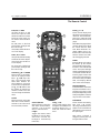
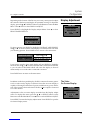
Alternate Remote Control
Functions Using the Shift
and Record/Zone 2 buttons
Shift
Digital Controller
EFFECTS
Record
Zone 2
FP FP OSD
OSD
OFF ON
DONE SELECT
Mute
Light
V
O
L
F
X
2 CH Party TV M Music
VCR DVD VDisc TV
AUX CD Tuner Tape
PGM trigger ONPGM trigger OFF
Menu background ON
Front/Back fader adjust
5dB-step master
volume adjust
Full mute ON/OFF
Tilt adjust
Loudness ON
Loudness OFF
CHURCH
CATHEDRAL
MONO LOGIC
MUSIC SURROUND
Menu background OFF
L/R Balance adjust
Bass level adjust
Treble level adjust
NIGHTCLUB
PANORAMA
2-CHANNEL
(Accesses optional
Expansion Ports)
CONCERT HALL
Loudness OFF, Bass,
Treble and Tilt to +0.0
Center balance
and fader
Press and hold with
buttons shown to
access these remote
control functions
You can access an additional set of controls with the DC-2 remote control by using
the Shift key.

5
DC-2 Digital Controller
Installation
Shift
Digital Controller
EFFECTS
Record
Zone 2
FP FP OSD
OSD
OFF ON
DONE SELECT
Mute
Light
V
O
L
F
X
2 CH Party TV M Music
VCR DVD VDisc TV
AUX CD Tuner Tape
Zone 2
outputs ON
Zone 2
outputs OFF
Display STATUS menu
(Press DONE to exit)
Zone 2
volume adjust
Zone 2
mute ON/OFF
Zone 2 L/R
Balance adjust
Select input for
Record/Zone 2
outputs)
In LOCK SETTINGS
menu, pressing with
SETTINGS selected
toggles double lock
Press and hold with
buttons shown
to access Record/
Zone 2 controls
Master volume
to -30dB
Master volume
to-10dB
Zone 2 volume
to-10dB
Zone 2 volume
to+00dB
Master volume
to+00dB
Zone 2 volume
to -30dB
Zone 2 volume
to -20dB
Master volume
to-20dB
Zone 2 controls are accessed by holding down the Record/Zone 2 button.

Lexicon
6
Installation
Connection
Location
Considerations The DC-2 is a highly specialized signal processing computer and requires
special care during installation to ensure optimum performance.
The DC-2 may be installed on a shelf or in a standard 19" equipment rack,
using an optional rack-mount kit available from Lexicon dealers. Observe
the following precautions:
• Select a dry, well-ventilated location out of direct sunlight.
• Do not stack the DC-2 directly above heat-producing equipment such as
power amplifiers.
• Avoid placing the DC-2 near unshielded TV or FM antennas, cable TV
decoders, or other receivers. The DC-2 may interfere with some FM
tuners if it is placed immediately above or below them. Some products,
particularly power amplifiers, may cause hum if they are in close
proximity.
• Make sure the DC-2 front panel IR receiver window is unobstructed. The
remote control must be in line-of-sight to this receiver for proper
operation. If line-of-sight is impractical, an infrared remote repeater can
be used with the rear panel IR connector. The DC-2 may be placed in a
glass-doored cabinet but smoked glass will make the front panel Liquid
Crystal Display (LCD) difficult to read and will reduce the sensitivity of
the IR receiver.
AC Connections The DC-2 is designed to be connected to an uninterrupted AC power line in
the same manner as a VCR or a television. We recommend the use of an AC
line filter to protect against line surges, or the installation of a line condi-
tioner to protect against under voltage (brownouts) as well as overvoltage
conditions.
The DC-2 has a master power switch on the rear panel above the IEC
standard AC power receptacle. This switch may be left ON continuously
when the unit is in regular use. When the DC-2 will not be used for an
extended period of time, or whenever you are connecting or disconnecting
any cables to the unit, this switch should be turned OFF.
Connect the power cable to the DC-2, then plug the power cord into a wall
outlet or into an unswitched outlet on a surge protector. Be sure that the
power cord is firmly seated in the connector on the rear panel of the DC-2.

7
DC-2 Digital Controller
Installation
Wiring Considerations
There is debate over the audible effects of different types of interconnects.
Good engineering practices have minimized the effect that cables might
have on the inputs and outputs of the DC-2 — but feel free to evaluate
different interconnects in your system. Be conscious, however, of the
mechanical stress from repeated insertion and overly tight connectors, and
the possibly corrosive nature of some contact-enhancing fluids.
Note that the use of standard audio cables for video or digital audio
applications may cause signal degradation, and is not recommended. For
these connections, please use only cables that are designed for the applica-
tion — these have different impedance characteristics than cables designed
for analog audio applications. Consult your dealer for recommendations.
All cables should be kept as short as possible.
In general, speaker cables should be kept short, and low-impedance wire
should be used throughout to assure efficient power transmission and
avoid audible distortion. Recommended wire lengths are given in the table
below. Although these examples can be used as a general guide, your
system manuals should provide detailed information specific to your
components.
Wire Lengths
Length AWG Size
up to 12 feet 16 gauge
up to 18 feet 14 gauge
up to 29 feet 12 gauge
up to 51 feet 10 gauge
Audio/Video Cables
Speaker Connections
Before making any connections, turn off ALL audio and video components,
including individual power amplifiers. (Unplug any preamps and power
amps that don’t have power switches.)
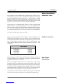
The DC-2 is designed to function as the control center of the system,
selecting inputs and controlling the volume of all speakers in the system.
The following diagram shows a system with a tape deck, an AM/FM tuner,
a CD player with a coaxial digital audio output, a satellite receiver with an
optical digital output, a DVD player and a VHS VCR. This example shows
the tape deck and VCR set up for recording and dual-zone audio.
Actual system connections will vary widely depending on the components
used. Consult your dealer for details on your particular requirements.
Audio/Video
Connections

Lexicon
8
Installation
Input sources should be connected directly to the DC-2 inputs. Since TAPE,
TUNER and CD are audio only, the video output will default to the video
signal from VCR. This allows TV or other video source viewing while
different audio is playing, but can be changed in the INPUT CONFIG menu.
Connect your main stereo amplifier to the DC-2 FRONT outputs. Connect
any additional amplifiers to the remaining outputs on the DC-2: side
amplifiers to the SIDE outputs, rear amplifiers to the REAR outputs, center-
channel amplifier to the CENTER output and the subwoofer amp to the
SUBWOOFER output. If you are using THX-type di-pole surround speak-
ers, the amplifier driving them should be connected to the DC-2 SIDE
outputs.
Whenever possible, connect both analog and digital outputs of digital
sources. This enables use of a digital input for the main zone, and the
corresponding analog input for the Record/Zone 2 outputs.
Note the use of Y-connectors to feed the DC-2 Record output to both the
VCR and the tape deck.
TAPE TUNER
AUDIO
S-VIDEO
MAIN OUTPUTS S/PDIF INTPUTS
VIDEO
INPUT OUTPUT POWER
TRIGGERS
TRIGGERS
GND
PGMPWR
RS 232
IR IN
CD AUX TV V-DISC DVD VCR ZONE 2
L
R
L
R
1
123
3
2
4
L
R
L
R
L
R
MONITOR
RECORD REAR SIDE CENTER
SUBWOOFER
FRONT
PGM GND PWR
EXPANSION PORTS
ABC
S/PDIF OUT
5
VIDEO DISC
PLAYER
Amplifiers and Speakers
CD
PLAYER
CABLE or
SATELLITE
SIDES
FRONTS
CENTER
SUBWOOFER
VCR
DVD
ZONE 2 AMPLIFIER
and SPEAKERS
TAPE
DECK
TUNER
VIDEO MONITOR
or PROCESOR
AC-3 RF
Optical or Coax Digital
LDD-1
to Lexicon
Amplifiers
In Out
Trigger
Video
Audio
Legend
REARS
DC-2 Connections

9
DC-2 Digital Controller
Installation
The DC-2 has five composite and S-Video inputs. Connection to an S-Video
input will override the composite signal connected via the RCA-type
connector. Note that an S-Video input will be output on both the composite
and S-Video outputs. Composite input signals will not be output as S-Video.
You can assign any video source to any (or all) of the eight DC-2 inputs via
the Input Configuration submenu of the Setup menu. This can be very
useful in systems which use a VCR as the tuner for TV viewing, as the video
feed from the VCR can be assigned to both the VCR and TV inputs. The
VCR's audio signals can be fed to both inputs with Y-connectors. (Do not use
Y-connectors on video signals.) This allows the audio and video signals
from the VCR to be used for both TV and VCR viewing.
You can also assign any video source to audio-only sources such as an AM/
FM tuner, to enjoy music from another source while viewing a video source.
It is important to remember that the impedance characteristics of composite
video and digital audio are different from analog audio. You should only
use cables specifically designed for video and digital audio. Consult your
dealer for recommendations.
The DC-2 has eight digital audio inputs: five coax via RCA and three optical
via TOSLINK™. The digital inputs can be set up to be selected with any (or
all) of the eight inputs via the Input Configuration menu. Using the digital
inputs will always provide superior performance.
Note that "AC-3 ready" laser disc and LD/DVD players output Dolby
Digital (AC-3) data from laser discs on a separate RCA jack in Radio
Frequency (RF) form. To maintain the exceptional performance of the DC-
2, an outboard demodulator is required to turn this RF signal back into a
digital bitstream. By performing the necessary demodulation outside the
DC-2, the potential for RF interference is eliminated. The Lexicon LDD-1 is
an excellent example of one such device.
Video Connections
Digital Audio Connections
"AC-3 Ready" Laser Disc and
LD/DVD Players

11
DC-2 Digital Controller
System
Configuration
2
System
Configuration
Restore
Factory Defaults
Although the DC-2 memory is cleared before it leaves the factory, it is good
practice to restore the factory defaults with the following procedure before
system configuration.
Turn the DC-2 OFF with the remote control. Turn the unit back ON and
immediately press and hold the MUTE button on the remote. (Make sure
you do not block the infrared receiver on the DC-2 front panel.) The display
will read:
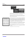
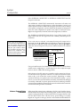
Press ▼ to highlight RESTORE DEFAULTS, then press SELECT. This will
clear and reload all preset effects and all factory settings of Volume,
Balance, Contrast, Configuration, etc. When the message FACTORY DE-
FAULTS RESTORED is displayed, press DONE to return to normal opera-
tion.
FACTORY PRESETS MENU
EXIT
RESTORE DEFAULTS
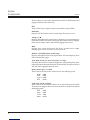
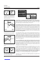
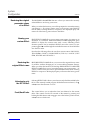
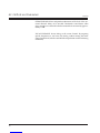
Equalization
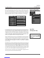
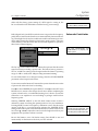
In the main menu, press SELECT to open the Equalization menu which
contains Bass, Treble and Tilt controls, and a Loudness parameter.
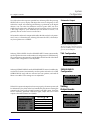
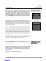
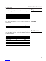
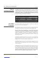
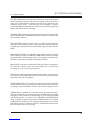
Bass and Treble level controls are provided to compensate for inconsisten-
cies in source material, rather than variations in room conditions. The BASS
LEVEL control allows a boost or cut of as much as 6dB below 250Hz. The
TREBLE LEVEL control allows a boost or cut of 6dB above 1.5kHz. To select
either control for adjustment, use ▲ or ▼ to select the control, press SELECT,
and use ▲ or ▼ to adjust the setting.
These controls do not affect the sound of rear or side speakers.
Bass and Treble Level
MAIN MENU
SETUP
EFFECT ADJUST
EQUALIZATION
DISPLAY ADJUST
EQUALIZATION MENU
BASS LEVEL
TREBLE LEVEL
TILT
LOUDNESS
-6.0 to +6.0dB
-6.0 to +6.0dB
-3.0dB to +3.0dB
ON, OFF
▲▼
Adjust with or
+0.0dB
+0.0dB
+0.0dB
ON

Lexicon
12
System
Configuration
20 100 1k 10k
(Hz)
(dB)
9.0000
7.0000
5.0000
3.0000
1.0000
-1.000
-3.000
-5.000
-7.000
-9.000
20k
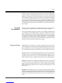
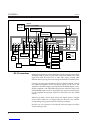
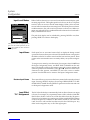
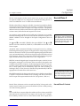
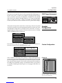
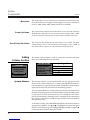
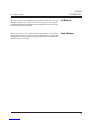
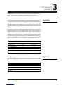
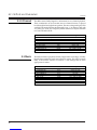
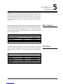
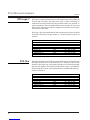
The Tilt parameter can be thought of as a straight line that pivots on a
fulcrum at 1kHz to correct the overall tonal balance of source material. The
range is -3.0dB to +3.0dB, referenced to the Treble level. This control,
adjustable in 0.2dB increments, is useful on many older recordings, or when
the desired tonal balance cannot be achieved at the listening position. The
Tilt control does not alter the tonal balance of the rear or side speakers.
Tilt
Tilt Control Frequency Response
20 100 1k 10k
(Hz)
(dB)
5.0000
4.0000
3.0000
2.0000
1.0000
0.0
-1.000
-2.000
-3.000
-4.000
20k
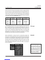
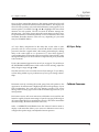
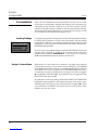
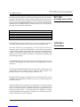
Loudness vs DC-2 Volume control
(front left)
20 100 1k 10k
(Hz)
(dB)
0.0
-10.00
-20.00
-30.00
-40.00
-50.00
-60.00
-70.00
-80.00 20k
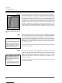
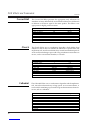
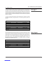
Loudness A Loudness Contour parameter which boosts bass information, provides
more balanced reproduction at low volume listening conditions. Once you
have calibrated DC-2 output levels, set the LOUDNESS parameter ON to
provide the ideal amount of boost for any given volume setting. This
parameter does not affect the sound of the rear or side speakers.
Bass Tone Control Frequency Response
20 100 1k 10k
(Hz)
(dB)
9.0000
7.0000
5.0000
3.0000
1.0000
-1.000
-3.000
-5.000
-7.000
-9.000
20k
Treble Tone Control Frequency
Response
La pagina si sta caricando...
La pagina si sta caricando...
La pagina si sta caricando...
La pagina si sta caricando...
La pagina si sta caricando...
La pagina si sta caricando...
La pagina si sta caricando...
La pagina si sta caricando...
La pagina si sta caricando...
La pagina si sta caricando...
La pagina si sta caricando...
La pagina si sta caricando...
La pagina si sta caricando...
La pagina si sta caricando...
La pagina si sta caricando...
La pagina si sta caricando...
La pagina si sta caricando...
La pagina si sta caricando...
La pagina si sta caricando...
La pagina si sta caricando...
La pagina si sta caricando...
La pagina si sta caricando...
La pagina si sta caricando...
La pagina si sta caricando...
La pagina si sta caricando...
La pagina si sta caricando...
La pagina si sta caricando...
La pagina si sta caricando...
La pagina si sta caricando...
La pagina si sta caricando...
La pagina si sta caricando...
La pagina si sta caricando...
La pagina si sta caricando...
La pagina si sta caricando...
La pagina si sta caricando...
La pagina si sta caricando...
La pagina si sta caricando...
La pagina si sta caricando...
La pagina si sta caricando...
La pagina si sta caricando...
La pagina si sta caricando...
La pagina si sta caricando...
La pagina si sta caricando...
La pagina si sta caricando...
La pagina si sta caricando...
La pagina si sta caricando...
La pagina si sta caricando...
-
 1
1
-
 2
2
-
 3
3
-
 4
4
-
 5
5
-
 6
6
-
 7
7
-
 8
8
-
 9
9
-
 10
10
-
 11
11
-
 12
12
-
 13
13
-
 14
14
-
 15
15
-
 16
16
-
 17
17
-
 18
18
-
 19
19
-
 20
20
-
 21
21
-
 22
22
-
 23
23
-
 24
24
-
 25
25
-
 26
26
-
 27
27
-
 28
28
-
 29
29
-
 30
30
-
 31
31
-
 32
32
-
 33
33
-
 34
34
-
 35
35
-
 36
36
-
 37
37
-
 38
38
-
 39
39
-
 40
40
-
 41
41
-
 42
42
-
 43
43
-
 44
44
-
 45
45
-
 46
46
-
 47
47
-
 48
48
-
 49
49
-
 50
50
-
 51
51
-
 52
52
-
 53
53
-
 54
54
-
 55
55
-
 56
56
-
 57
57
-
 58
58
-
 59
59
-
 60
60
-
 61
61
-
 62
62
-
 63
63
-
 64
64
-
 65
65
-
 66
66
-
 67
67


