ONKYO TX-NR 717 Manuale utente
- Categoria
- Ricevitori AV
- Tipo
- Manuale utente
Questo manuale è adatto anche per

E
n
AV RECEIVER
TX-NR717
Instruction Manual
Contents
Safety Information and Introduction ............2
Table of Contents...........................................6
Connections .................................................12
Turning On & Basic Operations..................20
Advanced Operations ..................................48
Controlling Other Components...................73
Appendix.......................................................80
Internet Radio Guide
Remote Control Codes

En-2
Safety Information and Introduction
Important Safety Instructions
1. Read these instructions.
2. Keep these instructions.
3. Heed all warnings.
4. Follow all instructions.
5. Do not use this apparatus near water.
6. Clean only with dry cloth.
7. Do not block any ventilation openings. Install in
accordance with the manufacturer’s instructions.
8. Do not install near any heat sources such as radiators,
heat registers, stoves, or other apparatus (including
amplifiers) that produce heat.
9. Do not defeat the safety purpose of the polarized or
grounding-type plug. A polarized plug has two blades
with one wider than the other. A grounding type plug
has two blades and a third grounding prong. The wide
blade or the third prong are provided for your safety. If
the provided plug does not fit into your outlet, consult
an electrician for replacement of the obsolete outlet.
10. Protect the power cord from being walked on or
pinched particularly at plugs, convenience receptacles,
and the point where they exit from the apparatus.
11. Only use attachments/accessories specified by the
manufacturer.
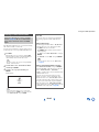
12. Use only with the cart, stand,
tripod, bracket, or table
specified by the manufacturer,
or sold with the apparatus.
When a cart is used, use
caution when moving the
cart/apparatus combination to
avoid injury from tip-over.
13. Unplug this apparatus during lightning storms or when
unused for long periods of time.
14. Refer all servicing to qualified service personnel.
Servicing is required when the apparatus has been
damaged in any way, such as power-supply cord or
plug is damaged, liquid has been spilled or objects
have fallen into the apparatus, the apparatus has been
exposed to rain or moisture, does not operate normally,
or has been dropped.
15. Damage Requiring Service
Unplug the apparatus from the wall outlet and refer
servicing to qualified service personnel under the
following conditions:
A. When the power-supply cord or plug is damaged,
B. If liquid has been spilled, or objects have fallen
into the apparatus,
C. If the apparatus has been exposed to rain or water,
D. If the apparatus does not operate normally by
following the operating instructions. Adjust only
those controls that are covered by the operating
instructions as an improper adjustment of other
controls may result in damage and will often
require extensive work by a qualified technician to
restore the apparatus to its normal operation,
E. If the apparatus has been dropped or damaged in
any way, and
F. When the apparatus exhibits a distinct change in
performance this indicates a need for service.
16. Object and Liquid Entry
Never push objects of any kind into the apparatus
through openings as they may touch dangerous voltage
points or short-out parts that could result in a fire or
electric shock.
The apparatus shall not be exposed to dripping or
splashing and no objects filled with liquids, such as
vases shall be placed on the apparatus.
Don’t put candles or other burning objects on top of
this unit.
17. Batteries
Always consider the environmental issues and follow
local regulations when disposing of batteries.
18. If you install the apparatus in a built-in installation,
such as a bookcase or rack, ensure that there is
adequate ventilation.
Leave 20 cm (8") of free space at the top and sides and
10 cm (4") at the rear. The rear edge of the shelf or
board above the apparatus shall be set 10 cm (4") away
from the rear panel or wall, creating a flue-like gap for
warm air to escape.
WARNING:
TO REDUCE THE RISK OF FIRE OR ELECTRIC SHOCK,
DO NOT EXPOSE THIS APPARATUS TO RAIN OR
MOISTURE.
CAUTION:
TO REDUCE THE RISK OF ELECTRIC SHOCK, DO NOT
REMOVE COVER (OR BACK). NO USER-SERVICEABLE
PARTS INSIDE. REFER SERVICING TO QUALIFIED
SERVICE PERSONNEL.
The lightning flash with arrowhead symbol, within an
equilateral triangle, is intended to alert the user to the
presence of uninsulated “dangerous voltage” within
the product’s enclosure that may be of sufficient
magnitude to constitute a risk of electric shock to
persons.
The exclamation point within an equilateral triangle is
intended to alert the user to the presence of important
operating and maintenance (servicing) instructions in
the literature accompanying the appliance.
WARNING
RISK OF ELECTRIC SHOCK
DO NOT OPEN
RISQUE DE CHOC ELECTRIQUE
NE PAS OUVRIR
AVIS
PORTABLE CART WARNIN
G
S3125A

Safety Information and Introduction
En-3
Precautions
1. Recording Copyright—Unless it’s for personal use
only, recording copyrighted material is illegal without
the permission of the copyright holder.
2. AC Fuse—The AC fuse inside the unit is not user-
serviceable. If you cannot turn on the unit, contact your
Onkyo dealer.
3. Care—Occasionally you should dust the unit all over
with a soft cloth. For stubborn stains, use a soft cloth
dampened with a weak solution of mild detergent and
water. Dry the unit immediately afterwards with a
clean cloth. Don’t use abrasive cloths, thinners,
alcohol, or other chemical solvents, because they may
damage the finish or remove the panel lettering.
4. Power
WARNING
BEFORE PLUGGING IN THE UNIT FOR THE
FIRST TIME, READ THE FOLLOWING SECTION
CAREFULLY.
AC outlet voltages vary from country to country. Make
sure that the voltage in your area meets the voltage
requirements printed on the unit’s rear panel (e.g., AC
230 V, 50 Hz or AC 120 V, 60 Hz).
The power cord plug is used to disconnect this unit
from the AC power source. Make sure that the plug is
readily operable (easily accessible) at all times.
For models with [POWER] button, or with both
[POWER] and [ON/STANDBY] buttons:
Pressing the [POWER] button to select OFF mode
does not fully disconnect from the mains. If you do not
intend to use the unit for an extended period, remove
the power cord from the AC outlet.
For models with [ON/STANDBY] button only:
Pressing the [ON/STANDBY] button to select
Standby mode does not fully disconnect from the
mains. If you do not intend to use the unit for an
extended period, remove the power cord from the AC
outlet.
5. Preventing Hearing Loss
Caution
Excessive sound pressure from earphones and
headphones can cause hearing loss.
6. Batteries and Heat Exposure
Warning
Batteries (battery pack or batteries installed) shall not
be exposed to excessive heat as sunshine, fire or the
like.
7. Never Touch this Unit with Wet Hands—Never
handle this unit or its power cord while your hands are
wet or damp. If water or any other liquid gets inside
this unit, have it checked by your Onkyo dealer.
8. Handling Notes
• If you need to transport this unit, use the original
packaging to pack it how it was when you originally
bought it.
• Do not leave rubber or plastic items on this unit for a
long time, because they may leave marks on the
case.
• This unit’s top and rear panels may get warm after
prolonged use. This is normal.
• If you do not use this unit for a long time, it may not
work properly the next time you turn it on, so be sure
to use it occasionally.
For U.S. models
FCC Information for User
CAUTION:
The user changes or modifications not expressly approved
by the party responsible for compliance could void the
user’s authority to operate the equipment.
NOTE:
This equipment has been tested and found to comply with
the limits for a Class B digital device, pursuant to Part 15
of the FCC Rules. These limits are designed to provide
reasonable protection against harmful interference in a
residential installation.
This equipment generates, uses and can radiate radio
frequency energy and, if not installed and used in
accordance with the instructions, may cause harmful
interference to radio communications. However, there is no
guarantee that interference will not occur in a particular
installation. If this equipment does cause harmful
interference to radio or television reception, which can be
determined by turning the equipment off and on, the user is
encouraged to try to correct the interference by one or more
of the following measures:
• Reorient or relocate the receiving antenna.
• Increase the separation between the equipment and
receiver.
• Connect the equipment into an outlet on a circuit different
from that to which the receiver is connected.
• Consult the dealer or an experienced radio/TV technician
for help.

Safety Information and Introduction
En-4
For Canadian Models
NOTE: THIS CLASS B DIGITAL APPARATUS
COMPLIES WITH CANADIAN ICES-003.
For models having a power cord with a polarized plug:
CAUTION: TO PREVENT ELECTRIC SHOCK,
MATCH WIDE BLADE OF PLUG TO WIDE SLOT,
FULLY INSERT.
Modèle pour les Canadien
REMARQUE: CET APPAREIL NUMÉRIQUE DE LA
CLASSE B EST CONFORME À LA NORME NMB-003
DU CANADA.
Sur les modèles dont la fiche est polarisée:
ATTENTION: POUR ÉVITER LES CHOCS
ÉLECTRIQUES, INTRODUIRE LA LAME LA PLUS
LARGE DE LA FICHE DANS LA BORNE
CORRESPONDANTE DE LA PRISE ET POUSSER
JUSQU’AU FOND.
For British models
Replacement and mounting of an AC plug on the power
supply cord of this unit should be performed only by
qualified service personnel.
IMPORTANT
The wires in the mains lead are coloured in accordance
with the following code:
Blue: Neutral
Brown: Live
As the colours of the wires in the mains lead of this
apparatus may not correspond with the coloured markings
identifying the terminals in your plug, proceed as follows:
The wire which is coloured blue must be connected to the
terminal which is marked with the letter N or coloured
black.
The wire which is coloured brown must be connected to
the terminal which is marked with the letter L or coloured
red.
IMPORTANT
The plug is fitted with an appropriate fuse. If the fuse needs
to be replaced, the replacement fuse must approved by
ASTA or BSI to BS1362 and have the same ampere rating
as that indicated on the plug. Check for the ASTA mark or
the BSI mark on the body of the fuse.
If the power cord’s plug is not suitable for your socket
outlets, cut it off and fit a suitable plug. Fit a suitable fuse
in the plug.
For European Models
Declaration of Conformity
We,
ONKYO EUROPE
ELECTRONICS GmbH
LIEGNITZERSTRASSE 6,
82194 GROEBENZELL,
GERMANY
GROEBENZELL, GERMANY
ONKYO EUROPE ELECTRONICS GmbH
K. MIYAGI
declare in own responsibility, that the ONKYO product
described in this instruction manual is in compliance with the
corresponding technical standards such as EN60065,
EN55013, EN55020 and EN61000-3-2, -3-3.

Safety Information and Introduction
En-5
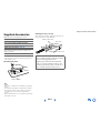
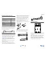
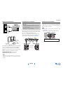
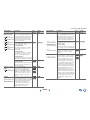
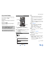
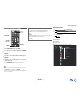
Supplied Accessories
Make sure you have the following accessories:
*
In catalogs and on packaging, the letter at the end of the product
name indicates the color. Specifications and operations are the
same regardless of color.
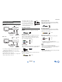
■ Installing the batteries
Note
• If the remote controller doesn’t work reliably, try replacing the
batteries.
• Don’t mix new and old batteries or different types of batteries.
• If you intend not to use the remote controller for a long time,
remove the batteries to prevent damage from leakage or
corrosion.
• Remove expired batteries as soon as possible to prevent damage
from leakage or corrosion.
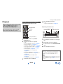
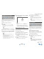
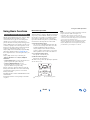
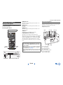
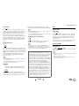
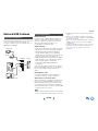
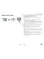
■ Aiming the remote controller
To use the remote controller, point it at the AV receiver’s
remote control sensor, as shown below.
Indoor FM antenna (➔ page 19)
AM loop antenna (➔ page 19)
Power cord (European, Australian, Asian and
Taiwanese models) (➔ page 19)
Speaker cable labels (➔ page 13)
Speaker setup microphone (➔ page 36)
Remote controller (RC-836M) and two batteries (AA/R6)
(Note for China: The battery for the remote controller is not
supplied for this unit.)
Quick Start Guide
Batteries (AA/R6)
Thank you for purchasing an Onkyo AV Receiver.
Please read this manual thoroughly before making
connections and plugging in the unit.
Following the instructions in this manual will
enable you to obtain optimum performance and
listening enjoyment from your new AV Receiver.
Please retain this manual for future reference.
Remote control sensor
AV receiver
Approx. 16 ft. (5 m)

Safety Information and Introduction
En-6
Table of Contents
Safety Information and Introduction
Important Safety Instructions ......................................2
Precautions ...................................................................3
Supplied Accessories...................................................5
Table of Contents..........................................................6
Features.........................................................................7
Front & Rear Panels......................................................8
Remote Controller.......................................................11
Connections
Connecting the AV Receiver......................................12
Connecting Your Speakers .......................................12
About AV Connections..............................................15
Connecting Components with HDMI .........................16
Connecting Your Components ..................................17
Connecting Onkyo RI Components...........................18
Connecting the Antennas..........................................19
Connecting the Power Cord ......................................19
Turning On & Basic Operations
Turning On/Off the AV Receiver ................................20
Turning On ................................................................20
Turning Off ................................................................20
Initial Setup..................................................................21
Selecting the Language
for the Onscreen Setup Menus...............................21
Audyssey 2EQ: Auto Setup.......................................21
Source Connection....................................................22
Remote Mode Setup .................................................22
Network Connection..................................................22
Terminating the Initial Setup .....................................22
Playback ......................................................................23
Playing the Connected Component ..........................23
Controlling Contents of USB or Network Devices..... 24
Understanding Icons on the Display .........................25
Playing an iPod/iPhone via USB............................... 25
Playing a USB Device............................................... 26
Listening to vTuner Internet Radio............................ 27
Registering Other Internet Radio ..............................28
Changing the Icon Layout
on the Network Service Screen.............................. 28
Playing Music Files on a Server ...............................29
Remote Playback...................................................... 29
Playing Music Files on a Shared Folder ...................30
Listening to AM/FM Radio ........................................31
Playing Audio and Video from Separate Sources..... 34
Using Basic Functions...............................................35
Using the Automatic Speaker Setup......................... 35
Using the Listening Modes .......................................38
Using the Home Menu ..............................................45
Using the Sleep Timer .............................................. 46
Setting the Display Brightness.................................. 46
Displaying Source Information.................................. 46
Changing the Input Display....................................... 46
Selecting Speaker Layout.........................................47
Using the Whole House Mode ..................................47
Muting the AV Receiver ............................................47
Using Headphones ...................................................47
Advanced Operations
On-screen Setup......................................................... 48
Using the Quick Setup ..............................................48
Using the Audio Settings of Quick Setup..................49
Using the Setup Menu (HOME) ................................51
About the HYBRID STANDBY Indicator ...................52
Setup Menu Items..................................................... 52
Input/Output Assign ..................................................53
Speaker Setup ..........................................................55
Audio Adjust.............................................................. 58
Source Setup ............................................................60
Listening Mode Preset ..............................................64
Miscellaneous ...........................................................65
Hardware Setup........................................................ 66
Remote Controller Setup .......................................... 69
Lock Setup................................................................ 69
Multi Zone ................................................................... 70
Making Multi Zone Connections ............................... 70
Controlling Multi Zone Components ......................... 71
Using the Remote Controller in
Zone and Multiroom Control Kits ........................... 72
Controlling Other Components
iPod/iPhone Playback via Onkyo Dock .................... 73
Using the Onkyo Dock.............................................. 73
Controlling Your iPod/iPhone ................................... 74
Controlling Other Components................................. 75
Preprogrammed Remote Control Codes .................. 75
Looking up for Remote Control Codes ..................... 75
Entering Remote Control Codes............................... 76
Remapping Colored Buttons .................................... 76
Remote Control Codes
for Onkyo Components Connected via RI ............. 77
Resetting the REMOTE MODE Buttons ................... 77
Resetting the Remote Controller .............................. 77
Controlling Other Components ................................. 77
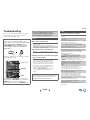
Appendix
Troubleshooting ......................................................... 80
Firmware Update ........................................................ 86
Connection Tips and Video Signal Path .................. 90
Using an RIHD-compatible TV, Player,
or Recorder .............................................................. 93
About HDMI................................................................. 95
Network/USB Features............................................... 96
License and Trademark Information ........................ 99
Specifications........................................................... 100
To reset the AV receiver to its factory defaults, turn it
on and, while holding down CBL/SAT, press
ON/STANDBY (➔ page 80).

Safety Information and Introduction
En-7
Features
Amplifier
• 110 Watts/Channel @ 8 ohms (FTC)
• 170 Watts/Channel @ 6 ohms (IEC)
• 185 Watts/Channel @ 6 ohms (JEITA)
• WRAT–Wide Range Amplifier Technology
(5 Hz to 100 kHz bandwidth)
• Linear Optimum Gain Volume Circuitry
• H.C.P.S. (High Current Power Supply) Massive High
Power Transformer
• 3 Stage Inverted Darlington Amplifier Design
Processing
• THX Select2 Plus Certified
• Incorporates Qdeo™ technology for HDMI Video
Upscaling (to 4K Compatible)
• HDMI (Audio Return Channel, 3D, DeepColor,
x.v.Color, Lip Sync, DTS-HD Master Audio, DTS-HD
High Resolution Audio, Dolby TrueHD, Dolby Digital
Plus, DSD and Multi-CH PCM)
• Dolby TrueHD and DTS-HD Master Audio
• Dolby Pro Logic IIz and Audyssey DSX
®
• Non-Scaling Configuration
• A-Form Listening Mode Memory
•Direct Mode
• Pure Audio Mode
• Music Optimizer for Compressed Digital Music files
• 192 kHz/24-bit D/A Converters
• Powerful and Highly Accurate 32-bit Processing DSP
• Jitter Cleaning Circuit Technology
Connections
• 8 HDMI Inputs (1 on front panel) and 2 Outputs
• Onkyo for System Control
• 5 Digital Inputs (2 Optical/3 Coaxial)
• Component Video Switching (2 Inputs/1 Output)
• Banana Plug-Compatible Speaker Posts
*
In Europe, using banana plugs to connect speakers to an audio
amplifier is prohibited.
• Powered Zone 2/3
• Bi-Amping Capability for FL/FR with FHL/FHR
• Analog RGB Video Input (D-sub 15) for PC
• Internet Radio Connectivity
• Network Capability for Streaming Audio Files
• 2 USB Inputs (Front/Rear) for Memory Devices and
iPod
®
/iPhone
®
models (Enables Display of Album
Artwork)
*
Only the front-panel USB input is compatible with
iPod/iPhone.
• MHL-Enabled AUX Front Input
Miscellaneous
• 40 FM/AM Presets
• Audyssey 2EQ
®
to correct room acoustic problems
• Audyssey Dynamic EQ
®
for loudness correction
• Audyssey Dynamic Volume
®
to maintain optimal
listening level and dynamic range
• Crossover Adjustment
(40/50/60/70/80/90/100/120/150/200 Hz)
• A/V Sync Control Function (up to 800 ms)
• Auto Standby Function
• On-Screen Display via HDMI
• Preprogrammed -Compatible Remote

Safety Information and Introduction
En-8
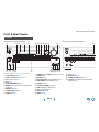
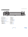
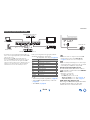
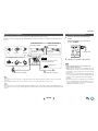
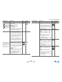
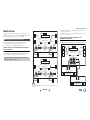
Front & Rear Panels
For detailed information, see the pages in parentheses.
ON/STANDBY button (20)
ZONE 2 and ZONE 3 buttons (47, 71)
Remote control sensor (5)
Display (9)
LISTENING MODE buttons (38)
DIMMER button (North American and Taiwanese
models) (46)
MEMORY button (32)
TUNING MODE button (32)
SETUP button (51)
TUNING / (32), PRESET / (32), cursor and
ENTER buttons
RETURN button
MASTER VOLUME control and indicator (23)
PURE AUDIO button and indicator (38)
PHONES jack (47)
AUX INPUT HDMI/MHL jack (16)
TONE and Tone Level buttons (49)
Input selector buttons (23)
DISPLAY button (46)
VIDEO jack (17)
USB port (17)
SETUP MIC jack (36)
HYBRID STANDBY indicator (52)
RT/PTY/TP button (European, Australian and
Asian models) (33)
Front Panel
(North American and Taiwanese models) (European, Australian and Asian models)

Safety Information and Introduction
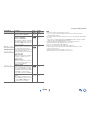
En-9
s
For detailed information, see the pages in parentheses.
Speaker/channel indicators
Z2 (Zone 2) indicator (71)
Z3 (Zone 3) indicator (71)
Listening mode and format indicators (38)
M.Opt indicator (50)
, and cursor indicators (25)
NET indicator (27 to 29, 31, 69)
Tuning indicators
RDS indicator (excluding North American and
Taiwanese models) (33)
AUTO indicator (32)
TUNED indicator (32)
FM STEREO indicator (32)
Input indicators (91)
HDMI indicator (67)
DIGITAL indicator
ANALOG indicator
Bi AMP indicator
Audyssey indicator (35, 60)
Dynamic EQ indicator (60)
Dynamic Vol indicator (61)
Headphone indicator (47)
Message area
MUTING indicator (47)
Volume level
USB indicator (25, 26)
SLEEP indicator (46)
Display

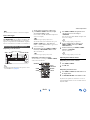
Safety Information and Introduction
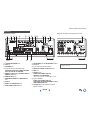
En-10
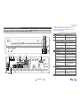
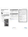
REMOTE CONTROL jack
USB port
ETHERNET port
Composite video and analog audio jacks
(BD/DVD IN, CBL/SAT IN, STB/DVR IN, GAME
IN, PC IN, TV/CD IN and PHONO IN)
HDMI IN and HDMI output (HDMI OUT MAIN and
HDMI OUT SUB) jacks
MONITOR OUT V jack
COMPONENT VIDEO IN and MONITOR OUT
jacks
IR IN jack
ZONE 2 12V TRIGGER OUT jack
ZONE 2/ZONE 3 LINE OUT jacks
FM ANTENNA jack and AM ANTENNA terminal
PC IN jack
Power cord (North American models)
DIGITAL IN COAXIAL and OPTICAL jacks
GND screw
PRE OUT jacks
(FRONT L/R, CENTER, SURR L/R,
SB/FH/FW
*
L/R, SUBWOOFER)
*
SB···Surround Back, FH···Front High, FW···Front Wide
Speaker Terminals
(FRONT L/R, CENTER, SURR L/R,
SURR BACK L/R, FRONT HIGH/ZONE 3 L/R and
FRONT WIDE/ZONE 2 L/R)
AC INLET (European, Australian, Asian and
Taiwanese models)
Rear Panel
(North American models) (European, Australian, Asian and Taiwanese models)
See “Connecting the AV Receiver” for connection
(➔ pages 12 to 19).

Safety Information and Introduction
En-11
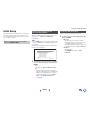
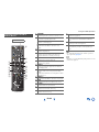
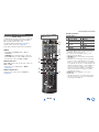
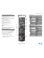
Remote Controller
For detailed information, see the pages in parentheses.
RECEIVER button (20)
REMOTE MODE/INPUT SELECTOR buttons (23)
SP (speaker layout) button (47)
// / and ENTER buttons
Q SETUP button (48)
Listening Mode buttons (38)
DIMMER button (46)
DISPLAY button (46)
MUTING button (47)
VOL / button (23)
RETURN button
HOME button (45)
SLEEP button (46)
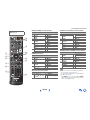
■ Controlling the tuner
To control the AV receiver’s tuner, press TUNER (or
RECEIVER).
You can select AM or FM by pressing TUNER repeatedly.
/ buttons ( 32)
D.TUN button (32)
DISPLAY button
CH +/– button (32)
Number buttons (32)
Controlling the AV Receiver
To control the AV receiver, press RECEIVER to select
Receiver mode.
You can also use the remote controller to control
Onkyo Blu-ray Disc/DVD player, CD player, and
other components.
See “Entering Remote Control Codes” for more
details (➔ page 76).

En-12
Connections
Connecting the AV
Receiver
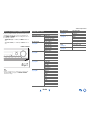
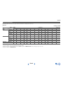
Speaker Configuration
The following table indicates the channels you should use
depending on the number of speakers that you have.
No matter how many speakers you use, a powered
subwoofer is recommended for a really powerful and solid
bass.
To get the best from your surround sound system, you need
to set the speaker settings automatically (➔ page 35) or
manually (➔ page 55).
*1
If you’re using only one surround back speaker, connect it to
the SURR BACK L terminals.
*2
Front high, surround back and front wide speakers cannot be
used at the same time.
Connecting Your Speakers
Number of
speakers
2 3 4 5 6 7 7 7 8 8 9 9 9 10 11
Front speakers ✔✔✔✔✔✔✔✔✔✔✔✔✔✔ ✔
Center speaker ✔ ✔✔✔✔✔✔✔✔✔✔✔ ✔
Surround
speakers
✔✔✔✔✔✔✔✔✔✔✔✔ ✔
Surround back
speaker
*1*2
✔✔✔✔
Surround back
speakers
*2
✔✔✔✔
Front high
speakers
*2
✔✔✔✔✔✔
Front wide
speakers
*2
✔✔✔✔✔✔
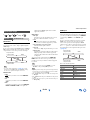
Connecting the Speaker Cables
The following illustration shows how to connect the
speakers to each pair of terminals. If you’re using only one
surround back speaker, connect it to the SURR BACK L
terminals.
Tip
• You can specify whether surround back, front high, or front wide
speakers are connected in the “Speaker Configuration” menu
(➔ page 55) or during Audyssey 2EQ
®
Room Correction and
Speaker Setup (➔ page 35).
■ Screw-type speaker terminals
Strip 1/2" to 5/8" (12 to 15 mm) of insulation from the ends
of the speaker cables, and twist the bare wires tightly, as
shown.
■ Banana Plugs (North American models)
• If you are using banana plugs, tighten the speaker
terminal before inserting the banana plug.
• Do not insert the speaker code directly into the center
hole of the speaker terminal.
Surround
back left
Surround
left
Surround
right
Front high
left
Front high
right Front leftFront right Center
Front wide
right
Front wide
left
Surround
back right
1/2" to 5/8" (12 to 15 mm)

Connections
En-13
Attaching the Speaker Cable Labels
The speaker terminals are color-coded for identification
purpose.
The supplied speaker cable labels are also color-coded and
you should attach them to the positive (+) side of each
speaker cable in accordance with the table above. Then all
you need to do is to match the color of each label to the
corresponding speaker terminal.
Speaker Connection Precautions
Read the following before connecting your speakers:
• You can connect speakers with an impedance of between
4 and 16 ohms. If the impedance of any of the connected
speakers is 4 ohms or more, but less than 6 ohms, be sure
to set the minimum speaker impedance to “4ohms”
(➔ page 55). If you use speakers with a lower
impedance, and use the amplifier at high volume levels
for a long period of time, the built-in protection circuit
may be activated.
• Disconnect the power cord from the wall outlet before
making any connections.
• Read the instructions supplied with your speakers.
• Pay close attention to speaker wiring polarity. In other
words, connect positive (+) terminals only to positive (+)
terminals, and negative (–) terminals only to negative (–)
terminals. If you get them the wrong way around, the
sound will be out of phase and will sound unnatural.
• Unnecessarily long, or very thin speaker cables may
affect the sound quality and should be avoided.
• Be careful not to short the positive and negative wires.
Doing so may damage the AV receiver.
• Make sure the metal core of the wire does not have
contact with the AV receiver’s rear panel. Doing so may
damage the AV receiver.
• Don’t connect more than one cable to each speaker
terminal. Doing so may damage the AV receiver.
• Don’t connect one speaker to several terminals.
Using Dipole Speakers
You can use dipole speakers for the surround and surround
back speakers. Dipole speakers output the same sound in
two directions.
Dipole speakers typically have an arrow printed on them to
indicate how they should be positioned. The surround
dipole speakers (a) should be positioned so that their
arrows point toward the TV/screen, while the surround
back dipole speakers (b) should be positioned so that their
arrows point toward each other, as shown.
Speaker Color
Front left, Front high left, Front wide left,
Zone 2 left, Zone 3 left
White
Front right, Front high right, Front wide
right, Zone 2 right, Zone 3 right
Red
Center Green
Surround left Blue
Surround right Gray
Surround back left Brown
Surround back right Tan
bb
aa
TV/screen

Connections
En-14
Using Powered Subwoofers
To find the best position for your subwoofer, while playing
a movie or some music with good bass, experiment by
placing your subwoofer at various positions within the
room, and choose the one that provides the most satisfying
results.
You can connect the powered subwoofer with two
SUBWOOFER PRE OUT jacks respectively.
The same signal is output from each jack.
Tip
• If your subwoofer is unpowered and you’re using an external
amplifier, connect the subwoofer pre out jack to an input on the
amplifier.
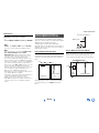
Bi-amping the Front Speakers
Bi-amping provides improved bass and treble performance.
When bi-amping is used, the AV receiver is able to drive
up to a 5.1 speaker system in the main room.
Once you’ve completed the bi-amping connections as
shown and turned on the AV receiver, you must set the
speaker setting to enable bi-amping (➔ page 55).
Connecting a Power Amplifier
If you want to use a more powerful power amplifier, you
can use the AV receiver as a preamp. Connect all speaker
outputs to the power amplifier. See the manuals supplied
with your amplifier for details.
Note
*1
Specify “None” for any channel that you don’t want to output
(➔ page 55).
SB···Surround Back, FH···Front High, FW···Front Wide
LINE INPUT
LINE INPUT
LINE INPUT
LINE INPUT
Powered subwoofer
Corner
position
1/3 of wall
position
Important:
• When making the bi-amping connections, be sure to remove
the jumper bars that link the speakers’ tweeter (high) and
woofer (low) terminals.
• Bi-amping can be used only with speakers that support bi-
amping. Refer to your speaker manual.
Tweeter (high)
Front right
Front left
Woofer (low)
L
R
Power amplifier
*1

Connections
En-15
Connecting AV components
a
*1
If your TV doesn’t support Audio Return Channel (ARC), you
need to connect an optical digital cable together with the
HDMI cable to the AV receiver.
• Before making any AV connections, read the manuals
supplied with your AV components.
• Don’t connect the power cord until you’ve completed and
double-checked all AV connections.
• Push plugs in all the way to make
good connections (loose connections
can cause noise or malfunctions).
• To prevent interference, keep audio
and video cables away from power
cords and speaker cables.
AV Cables and Jacks
■ HDMI
HDMI connections can carry digital video and audio.
■ Component video
Component video separates the luminance (Y) and color
difference signals (P
B, PR), providing the best picture
quality (some TV manufacturers label their component
video sockets slightly differently).
■ Analog RGB
This is a conventional analog interface to connect a PC and
a display device (also called D-Sub or D-subminiature).
■ Composite video
Composite video is commonly used on TVs, DVDs, and
other video equipment.
■ Optical digital audio
Optical digital connections allow you to enjoy digital
sound such as PCM
*2
, Dolby Digital or DTS. The audio
quality is the same as coaxial.
■ Coaxial digital audio
Coaxial digital connections allow you to enjoy digital
sound such as PCM
*2
, Dolby Digital or DTS. The audio
quality is the same as optical.
■ Analog audio (RCA)
Analog audio connections (RCA) carry analog audio.
*2
For PCM signals, the supported sampling rates are
32/44.1/48/88.2/96 kHz. With HDMI connections, 176.4 and
192 kHz are also supported.
Note
• The AV receiver does not support SCART plugs.
• The AV receiver’s optical digital jacks have shutter-type covers
that open when an optical plug is inserted and close when it’s
removed. Push plugs in all the way.
Caution
• To prevent shutter damage, hold the optical plug straight
when inserting and removing.
About AV Connections
HDMI cable
Other cables
: Video & Audio
: Video
Game console
Blu-ray Disc/
DVD player
TV, projector, etc.
AV receiver
TV, projector, etc.
AV receiver
Game console
Blu-ray Disc/
DVD player
: Audio
*1
Green
Blue
Red
Yellow
Right!
Wrong!
Y
P
B
PR
Orange
White
Red

Connections
En-16
*
If your TV doesn’t support Audio Return Channel (ARC), you
need to connect an optical digital cable together with the HDMI
cable to the AV receiver.
*
When listening to an HDMI component through the AV
receiver, set the HDMI component so that its video can be seen
on the TV screen (on the TV, select the input of the HDMI
component connected to the AV receiver). If the TV power is off
or the TV is set to another input source, this may result in no
sound from the AV receiver or the sound may be cut off.
Connect your components to the appropriate jacks. The
default input assignments are shown below.
✔: Assignment can be changed (➔ page 53).
See also:
• “Connection Tips and Video Signal Path” (➔ page 90)
• “Using an RIHD-compatible TV, Player, or Recorder”
(➔ page 93)
• “About HDMI” (➔ page 95)
Tip
• To listen to the audio of a component connected via HDMI
through your TV’s speakers, enable “HDMI Through”
(➔ page 67) and set the AV receiver to standby mode.
Note
• In the case of Blu-ray Disc/DVD players, if no sound is output
despite following the above-mentioned procedure, set your Blu-
ray Disc/DVD player’s HDMI audio settings to PCM.
■ Audio Return Channel (ARC) function
The Audio Return Channel (ARC) function enables an
HDMI capable TV to send the audio stream to HDMI OUT
MAIN on the AV receiver.
• This function can be used when:
– Your TV is ARC capable, and
–The TV/CD input selector is selected, and
–“HDMI Control(RIHD)” is set to “On”(➔ page 67), and
–“Audio Return Channel” is set to “Auto” (➔ page 67).
■ MHL (Mobile High-Definition Link)
With its support for MHL (Mobile High-Definition Link),
the AUX (Front) input allows you to deliver high-
definition video from a connected mobile device.
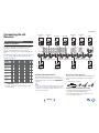
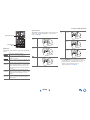
Connecting Components with HDMI
Game console
TV, projector, etc.
Satellite/cable set-top box, etc.
Blu-ray Disc/DVD player
Personal computer
Camcorder, etc.
Set top box/digital video recorder, etc.
Jack Components
IN1 Blu-ray Disc/DVD player ✔
IN2 Satellite/cable set-top box, etc. ✔
IN3 Set top box/digital video recorder, etc. ✔
IN4 Game console ✔
IN5 Personal computer ✔
IN6 Other components ✔
IN7 Other components ✔
Front Camcorder, etc.
OUT MAIN TV
OUT SUB Projector, etc.

Connections
En-17
Connecting Your Components
The on-screen menus appear only on a TV that is connected to HDMI OUT MAIN. If your TV is connected to other
video outputs, use the AV receiver’s display when changing settings.
GND screw
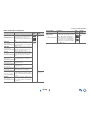
Connect your components to the appropriate jacks. The
default input assignments are shown below. See
“Connection Tips and Video Signal Path” for more
information (➔ page 90).
✔: Assignment can be changed (➔ page 54).
No. Jack/Port Components
USB, VIDEO
*1
iPod/iPhone (video
playback)
USB
*2*3
iPod/iPhone, MP3 player,
USB flash drive
DIGITAL IN
COAXIAL 1 (BD/DVD) Blu-ray Disc/DVD player ✔
COAXIAL 2 (CBL/SAT) Satellite/cable set-top box,
etc.
✔
COAXIAL 3 (STB/DVR) Set top box/digital video
recorder, etc
✔
OPTICAL 1 (GAME) Game consoles ✔
OPTICAL 2 (TV/CD) TV, CD player ✔
ETHERNET Router
MONITOR OUT TV, projector, etc.
BD/DVD IN Blu-ray Disc/DVD player
CBL/SAT IN Satellite/cable set-top box,
etc.
STB/DVR IN Set top box/digital video
recorder, etc
GAME IN Game console, RI dock
PC IN Personal computer
TV/CD IN TV, CD player, cassette
tape deck, MD, CD-R,
Turntable
*4
, RI dock
PHONO IN
Turntable
*4
COMPONENT VIDEO
MONITOR OUT TV, projector, etc.
IN 1 (BD/DVD) Blu-ray Disc/DVD player,
RI dock
✔
IN 2 (CBL/SAT) Satellite/cable set-top box,
RI dock, etc.
✔
PC IN
*5
Personal computer

Connections
En-18
Note
*1
When the USB input is selected, you can input video signals
from the VIDEO jack. Video signals input from VIDEO will
be output from the MONITOR OUT V and HDMI output
jacks.
*2
Do not connect the AV receiver’s USB port to a USB port on
your computer. Music on your computer cannot be played
through the AV receiver in this way.
*3
Only the front-panel USB input is compatible with
iPod/iPhone.
*4
Connect a turntable (MM) that has a built-in phono preamp to
TV/CD IN, or connect it to PHONO IN with the phono
preamp turned off. If your turntable (MM) doesn’t have a
phono preamp, connect it to PHONO IN. If your turntable has
a moving coil (MC) type cartridge, you’ll need a commercially
available MC head amp or MC transformer to connect to
PHONO IN. See your turntable’s manual for details.
If your turntable has a ground wire, connect it to the AV
receiver’s GND screw. With some turntables, connecting the
ground wire may produce an audible hum. If this happens,
disconnect it.
*5
When you connect your personal computer to PC IN and select
the PC input selector, the video of the personal computer is
output from the HDMI outputs. However, if you have assigned
the HDMI inputs to the PC input selector, the AV receiver will
output signals received from the HDMI inputs instead of
signals from PC IN. To have the signals output from PC IN,
select “-----” for “PC” in the “HDMI Input” setting
(➔ page 53).
• With connection , you can enjoy Dolby Digital and
DTS. (To listen in Zone 2/3 as well, use and .)
• With connection , you can enjoy audio from external
components while you are in Zone 2/3.
• With connection , if your Blu-ray Disc/DVD player
has both the main stereo and multichannel outputs, be
sure to connect the main stereo.
With (Remote Interactive), you can use the following
special functions:
■ System On/Auto Power On
When you start playback on a component connected via
, while the AV receiver is on standby, the AV
receiver will automatically turn on and select that
component as the input source.
■ Direct Change
When playback is started on a component connected via
, the AV receiver automatically selects that
component as the input source.
■ Remote Control
You can use the AV receiver’s remote controller to
control your other -capable Onkyo components,
pointing the remote controller at the AV receiver’s
remote control sensor instead of the component. You
must enter the appropriate remote control code first
(➔ page 77).
Note
•Use only cables for connections. cables are supplied
with Onkyo components.
• Some components have two jacks. You can connect either
one to the AV receiver. The other jack is for connecting
additional -capable components.
• Connect only Onkyo components to jacks. Connecting other
manufacturer’s components may cause a malfunction.
• Some components may not support all functions. Refer to the
manuals supplied with your Onkyo components.
• While Zone 2/3 is on, the System On/Auto Power On and Direct
Change functions do not work.
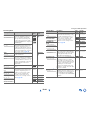
Connecting Onkyo RI Components
1
Make sure that each Onkyo component is connected
with an analog audio cable (connection
in the
hookup examples) (➔ page 17).
2
Make the connection (see the illustration).
3
If you’re using an RI Dock, or cassette tape deck,
change the Input Display (➔ page 46).
L R
ANALOG
AUDIO OUT
L R
ANALOG
AUDIO OUT
e.g., cassette tape deck
RI Dock

Connections
En-19
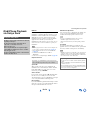
This section explains how to connect the supplied indoor FM antenna and AM loop antenna.
The AV receiver won’t pick up any radio signals without any antenna connected, so you must connect the antenna to use
the tuner.
Note
• Once your AV receiver is ready for use, you’ll need to tune into a radio station and position the antenna to achieve the best possible
reception.
• Keep the AM loop antenna as far away as possible from your AV receiver, TV, speaker cables, and power cords.
Tip
• If you cannot achieve good reception with the supplied indoor FM antenna, try a commercially available outdoor FM antenna instead.
• If you cannot achieve good reception with the supplied indoor AM loop antenna, try using it with a commercially available outdoor AM
antenna.
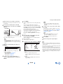
Connecting the Antennas
Thumbtacks, etc.
Insert the plug fully
into the jack.
Insert the plug fully
into the jack.
North American and
Taiwanese models
European, Australian
and Asian models
Push. Insert wire. Release.
Assembling the AM loop antenna
Indoor FM antenna (supplied)AM loop antenna (supplied)
Caution
• Be careful not to injure yourself
when using thumbtacks.
Note
• Before connecting the power cord, connect all of your
speakers and AV components.
• Turning on the AV receiver may cause a momentary power surge
that might interfere with other electrical equipment on the same
circuit. If this is a problem, plug the AV receiver into a different
branch circuit.
• Do not use a power cord other than the one supplied with the AV
receiver. The supplied power cord is designed exclusively for use
with the AV receiver and should not be used with any other
equipment.
• Never disconnect the power cord from the AV receiver while the
other end is still plugged into a wall outlet. Doing so may cause
an electric shock. Always disconnect the power cord from the
wall outlet first, and then the AV receiver.
Connecting the Power Cord
1
(European, Australian, Asian and Taiwanese
models)
Connect the supplied power cord to the AV
receiver’s AC INLET.
2
Plug the power cord into an AC wall outlet.
To AC wall outlet

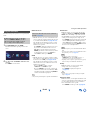
En-20
Turning On & Basic Operations
Turning On/Off the AV
Receiver
Tip
•The HYBRID STANDBY indicator may light depending on the
status of settings (➔ page 52).
• For details on power management settings, see “Auto Standby”
(➔ page 68).
RECEIVER
RECEIVER
ON/STANDBY
Turning On
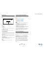
1
Press ON/STANDBY on the front panel.
or
Press RECEIVER followed by RECEIVER on the
remote controller.
The AV receiver comes on and its display lights.
Turning Off
1
Press ON/STANDBY on the front panel.
or
Press RECEIVER followed by RECEIVER on the
remote controller.
The AV receiver will enter standby mode. To prevent
any loud surprises when you turn on the AV receiver,
always turn down the volume before you turn it off.
■ Smooth Operation in a Few Easy Steps
(Initial Setup)
To ensure smooth operation, here’s a few easy steps to
help you configure the AV receiver before you use it for
the very first time. These settings only need to be made
once. See “Initial Setup” for details (➔ page 21).
■ If the “Firmware Update Available” window
appears.
When a new version of the firmware is available, the
notification window “Firmware Update Available”
pops up. This notification only appears when the AV
receiver is connected to your home network
(➔ page 96). To perform the firmware update, follow
the instructions on screen.
Use / and ENTER on the AV receiver or remote
controller to select one of the options.
` Update Now:
Starts the firmware update.
Refer to “Firmware Update” (➔ page 86).
` Remind me Later:
The update notification will pop up again the next
time you turn the AV receiver on.
` Never Remind me:
Disables the automatic update notification.
Tip
• The update notification window can be enabled or disabled in
“Update Notice” (➔ page 69).
La pagina si sta caricando...
La pagina si sta caricando...
La pagina si sta caricando...
La pagina si sta caricando...
La pagina si sta caricando...
La pagina si sta caricando...
La pagina si sta caricando...
La pagina si sta caricando...
La pagina si sta caricando...
La pagina si sta caricando...
La pagina si sta caricando...
La pagina si sta caricando...
La pagina si sta caricando...
La pagina si sta caricando...
La pagina si sta caricando...
La pagina si sta caricando...
La pagina si sta caricando...
La pagina si sta caricando...
La pagina si sta caricando...
La pagina si sta caricando...
La pagina si sta caricando...
La pagina si sta caricando...
La pagina si sta caricando...
La pagina si sta caricando...
La pagina si sta caricando...
La pagina si sta caricando...
La pagina si sta caricando...
La pagina si sta caricando...
La pagina si sta caricando...
La pagina si sta caricando...
La pagina si sta caricando...
La pagina si sta caricando...
La pagina si sta caricando...
La pagina si sta caricando...
La pagina si sta caricando...
La pagina si sta caricando...
La pagina si sta caricando...
La pagina si sta caricando...
La pagina si sta caricando...
La pagina si sta caricando...
La pagina si sta caricando...
La pagina si sta caricando...
La pagina si sta caricando...
La pagina si sta caricando...
La pagina si sta caricando...
La pagina si sta caricando...
La pagina si sta caricando...
La pagina si sta caricando...
La pagina si sta caricando...
La pagina si sta caricando...
La pagina si sta caricando...
La pagina si sta caricando...
La pagina si sta caricando...
La pagina si sta caricando...
La pagina si sta caricando...
La pagina si sta caricando...
La pagina si sta caricando...
La pagina si sta caricando...
La pagina si sta caricando...
La pagina si sta caricando...
La pagina si sta caricando...
La pagina si sta caricando...
La pagina si sta caricando...
La pagina si sta caricando...
La pagina si sta caricando...
La pagina si sta caricando...
La pagina si sta caricando...
La pagina si sta caricando...
La pagina si sta caricando...
La pagina si sta caricando...
La pagina si sta caricando...
La pagina si sta caricando...
La pagina si sta caricando...
La pagina si sta caricando...
La pagina si sta caricando...
La pagina si sta caricando...
La pagina si sta caricando...
La pagina si sta caricando...
La pagina si sta caricando...
La pagina si sta caricando...
La pagina si sta caricando...
La pagina si sta caricando...
La pagina si sta caricando...
La pagina si sta caricando...
La pagina si sta caricando...
La pagina si sta caricando...
La pagina si sta caricando...
La pagina si sta caricando...
La pagina si sta caricando...
La pagina si sta caricando...
La pagina si sta caricando...
La pagina si sta caricando...
La pagina si sta caricando...
La pagina si sta caricando...
La pagina si sta caricando...
La pagina si sta caricando...
La pagina si sta caricando...
La pagina si sta caricando...
La pagina si sta caricando...
La pagina si sta caricando...
La pagina si sta caricando...
La pagina si sta caricando...
La pagina si sta caricando...
La pagina si sta caricando...
La pagina si sta caricando...
La pagina si sta caricando...
La pagina si sta caricando...
La pagina si sta caricando...
La pagina si sta caricando...
La pagina si sta caricando...
La pagina si sta caricando...
La pagina si sta caricando...
La pagina si sta caricando...
La pagina si sta caricando...
La pagina si sta caricando...
La pagina si sta caricando...
La pagina si sta caricando...
La pagina si sta caricando...
La pagina si sta caricando...
La pagina si sta caricando...
La pagina si sta caricando...
La pagina si sta caricando...
La pagina si sta caricando...
La pagina si sta caricando...
La pagina si sta caricando...
La pagina si sta caricando...
La pagina si sta caricando...
La pagina si sta caricando...
-
 1
1
-
 2
2
-
 3
3
-
 4
4
-
 5
5
-
 6
6
-
 7
7
-
 8
8
-
 9
9
-
 10
10
-
 11
11
-
 12
12
-
 13
13
-
 14
14
-
 15
15
-
 16
16
-
 17
17
-
 18
18
-
 19
19
-
 20
20
-
 21
21
-
 22
22
-
 23
23
-
 24
24
-
 25
25
-
 26
26
-
 27
27
-
 28
28
-
 29
29
-
 30
30
-
 31
31
-
 32
32
-
 33
33
-
 34
34
-
 35
35
-
 36
36
-
 37
37
-
 38
38
-
 39
39
-
 40
40
-
 41
41
-
 42
42
-
 43
43
-
 44
44
-
 45
45
-
 46
46
-
 47
47
-
 48
48
-
 49
49
-
 50
50
-
 51
51
-
 52
52
-
 53
53
-
 54
54
-
 55
55
-
 56
56
-
 57
57
-
 58
58
-
 59
59
-
 60
60
-
 61
61
-
 62
62
-
 63
63
-
 64
64
-
 65
65
-
 66
66
-
 67
67
-
 68
68
-
 69
69
-
 70
70
-
 71
71
-
 72
72
-
 73
73
-
 74
74
-
 75
75
-
 76
76
-
 77
77
-
 78
78
-
 79
79
-
 80
80
-
 81
81
-
 82
82
-
 83
83
-
 84
84
-
 85
85
-
 86
86
-
 87
87
-
 88
88
-
 89
89
-
 90
90
-
 91
91
-
 92
92
-
 93
93
-
 94
94
-
 95
95
-
 96
96
-
 97
97
-
 98
98
-
 99
99
-
 100
100
-
 101
101
-
 102
102
-
 103
103
-
 104
104
-
 105
105
-
 106
106
-
 107
107
-
 108
108
-
 109
109
-
 110
110
-
 111
111
-
 112
112
-
 113
113
-
 114
114
-
 115
115
-
 116
116
-
 117
117
-
 118
118
-
 119
119
-
 120
120
-
 121
121
-
 122
122
-
 123
123
-
 124
124
-
 125
125
-
 126
126
-
 127
127
-
 128
128
-
 129
129
-
 130
130
-
 131
131
-
 132
132
-
 133
133
-
 134
134
-
 135
135
-
 136
136
-
 137
137
-
 138
138
-
 139
139
-
 140
140
-
 141
141
-
 142
142
-
 143
143
-
 144
144
-
 145
145
-
 146
146
-
 147
147
-
 148
148


ONKYO TX-NR 717 Manuale utente
- Categoria
- Ricevitori AV
- Tipo
- Manuale utente
- Questo manuale è adatto anche per
in altre lingue
- English: ONKYO TX-NR 717 User manual
Documenti correlati
-
ONKYO HT-RC440 Manuale del proprietario
-
ONKYO TX-NR 616 Manuale utente
-
-
ONKYO TX-NR515 Manuale utente
-
ONKYO TX-NR414 Manuale utente
-
ONKYO TX-NR727 Manuale del proprietario
-
ONKYO MS-100 HCP and Manuale utente
-
-
ONKYO TX-NR838 Manuale del proprietario
-
ONKYO TX-NR535 Manuale utente
Altri documenti
-
Revo Heritage G1 & G2 Manuale del proprietario
-
TEAC NS-X1 Manuale del proprietario
-
Philips WAS6050/05 Manuale utente
-
Tascam PA-R100 Remote Control Code
-
Arcam UDP411 Manuale utente
-
Cambridge Audio DVD57 Istruzioni per l'uso
-
Panasonic SAHE70 Manuale del proprietario
-
-
 Retekess V116 Manuale utente
-
Fusion MS-UD/AV750 Manuale del proprietario
