

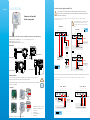
English Quick Start Guide
Humidity and temperature
transmitter
Operating temperature, protection of the instruments and information about storage
Conditions of use (°C/%RH/m): from -10 to +50 °C; in non-condensing conditions. From 0 to 2000 m.
Protection: IP65(2) or IP20(1)
Storage temperature: from -10 to +70 °C.
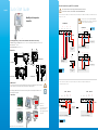
Dimensions
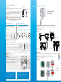
Electrical connections as per NFC15-100 standard
This connection must be made by a qualied and trained technician.
To make the connection, the transmitter must NOT BE ENERGIZED.
To make a 3-wire connection, BEFORE POWERING
UPthe transmitter, please connect the output ground
to the input ground. See drawing below.
Symbols used
For your safety and in order to avoid any damage of the device, please follow the procedure described in
this document and read carefully the notes preceded by the following symbol:
The following symbol will also be used in this document, please read carefully the information notes
indicated after this symbol:
1 2 3 4 5 6 7
+ - + - +
type passif
VV
+
-Alimentation 24 Vdc
ou
VT GND VRH VT GND VRH
1 2 3 4 5 6 7
N L
6 7
ou
automate type passif
+ - + - +
++ -
++ -
VV
Alimentation
24 Vdc
Alimentation 24 Vac
Classe II
+-
L
L
N
N
A
+
+
+
+
-
-
-
-
1 2 3 4 5 6 7
- +- +
Alimentation
16-30 Vdc ou
IRH VdcIT Vdc
1 2 3 4 5 6 7
- +- +
IRH VdcIT Vdc
type actiftype passif
A
+-
A
+-
1 2 3 4 5 6 7
+ - + - +
type passif
VV
Alimentation 24 Vdc
++ -
16-30 Vdc 16-30 Vdc
Alimentation 16-30 Vdc
A
régulateur
ou automate
type passif
1 2 3 4 5 6 7
+ - + - +
Regulador/PLC/BMS tipo PASIVO
VV
+
-Alimentación 24 Vdc
o
VT GND VRH VT GND VRH
1 2 3 4 5 6 7
N L
6 7
o
+ - + - +
++ -
++ -
VV
Alimentación
24 Vdc
Alimentación 24 Vac
Class II
+-
L
L
N
N
A
+
+
+
+
-
-
-
-
1 2 3 4 5 6 7
- +- +
Alimentación
16-30 Vdc o
IRH VdcIT Vdc
1 2 3 4 5 6 7
- +- +
IRH VdcIT Vdc
Display/regulador/PLC/BMS tipo ACTIVODisplay/regulador/PLC/BMS tipo PASSIVO
A
+-
A
+-
1 2 3 4 5 6 7
+ - + - +
Regulador/PLC/BMS tipo PASIVO
VV
Alimentación 24 Vac
Class II
++ -
16-30 Vdc 16-30 Vdc
Alimentación 16-30 Vdc
A
Display/regu-
lador/PLC/BMS
tipo PASIVO
4 hilos
4 hilos
Display/regulador/PLC/BMS
tipo PASIVO
3 hilos
3 hilos
3 hilos
2 hilos
2 hilos
2 hilos
2 hilos
1 2 3 4 5 6 7
+ - + - +
VV
+
-Power supply 24 Vdc
or
VT GND VRH
VT GND VRH
1 2 3 4 5 6 7
N L
6 7
or
+ - + - +
++ -
++ -
VV
Power supply
24 Vdc
Power supply 24 Vac
Class II
+-
L
L
N
N
A
+
+
+
+
-
-
-
-
1 2 3 4 5 6 7
- +- +
Power supply
16-30 Vdc or
IRH VdcIT Vdc
1 2 3 4 5 6 7
- +- +
IRH VdcIT Vdc
A
+-
A
+-
1 2 3 4 5 6 7
+ - + - +
VV
Power supply 24 Vdc
++ -
16-30 Vdc 16-30 Vdc
Power supply 16-30 Vdc
A
Display/regulator/PLC
passive type
4 wires
3 wires
2 wires
4 wires
3 wires
2 wires 2 wires 2 wires
Display/regulator/PLC passive type
Display/regulator/PLC passive type
Display/regulator/PLC passive type
Display/
regulator/PLC
passive type
Display/regulator/PLC active type
3 wires
1 2 3 4 5 6 7
+ - + - +
VV
+
-Alimentazione 24 Vdc
o
VT GND VRH VT GND VRH
1 2 3 4 5 6 7
N L
6 7
o
+ - + - +
++ -
++ -
VV
Alimentazione
24 Vdc
Alimentazione 24 Vac
Class II
+-
L
L
N
N
A
+
+
+
+
-
-
-
-
1 2 3 4 5 6 7
- +- +
Alimentazione
16-30 Vdc o
IRH VdcIT Vdc
1 2 3 4 5 6 7
- +- +
IRH VdcIT Vdc
A
+-
A
+-
1 2 3 4 5 6 7
+ - + - +
VV
Alimentazione 24 Vdc
++ -
16-30 Vdc 16-30 Vdc
Alimentazione16-30 Vdc
A
Display regolatore o
PLC/BMS tipo passivo
4 li
3 li
2 li
4 li 3 li
2 li 2 li 2 li
Display regolatore o PLC/BMS tipo passivo
Display regolatore o PLC/BMS tipo passivo
Display regolatore o PLC/BMS tipo passivo
Display
regolatore o
PLC/BMS tipo
passivo
Display regolatore o PLC/BMS tipo attivo
3 li
1 2 3 4 5 6 7
+ - + - +
type passif
VV
+
-
Alimentation 24 Vdc
ou
VT GND VRH VT GND VRH
1 2 3 4 5 6 7
N L
6 7
ou
automate type passif
+ - + - +
++ -
++ -
VV
Alimentation
24 Vdc
Alimentation 24 Vac
Classe II
+-
L
L
N
N
A
+
+
+
+
-
-
-
-
1 2 3 4 5 6 7
- +- +
Alimentation
16-30 Vdc
ou
IRH VdcIT Vdc
1 2 3 4 5 6 7
- +- +
IRH VdcIT Vdc
type actiftype passif
A
+-
A
+-
1 2 3 4 5 6 7
+ - + - +
type passif
VV
Alimentation 24 Vdc
++ -
16-30 Vdc 16-30 Vdc
Alimentation 16-30 Vdc
A
régulateur
ou automate
type passif
1 2 3 4 5 6 7
+ - + - +
Regulador/PLC/BMS tipo PASIVO
VV
+
-
Alimentación 24 Vdc
o
VT GND VRH VT GND VRH
1 2 3 4 5 6 7
N L
6 7
o
+ - + - +
++ -
++ -
VV
Alimentación
24 Vdc
Alimentación 24 Vac
Class II
+-
L
L
N
N
A
+
+
+
+
-
-
-
-
1 2 3 4 5 6 7
- +- +
Alimentación
16-30 Vdc
o
IRH VdcIT Vdc
1 2 3 4 5 6 7
- +- +
IRH VdcIT Vdc
Display/regulador/PLC/BMS tipo ACTIVODisplay/regulador/PLC/BMS tipo PASSIVO
A
+-
A
+-
1 2 3 4 5 6 7
+ - + - +
Regulador/PLC/BMS tipo PASIVO
VV
Alimentación 24 Vac
Class II
++ -
16-30 Vdc 16-30 Vdc
Alimentación 16-30 Vdc
A
Display/regu-
lador/PLC/BMS
tipo PASIVO
4 hilos
4 hilos
Display/regulador/PLC/BMS
tipo PASIVO
3 hilos
3 hilos
3 hilos
2 hilos
2 hilos
2 hilos
2 hilos
1 2 3 4 5 6 7
+ - + - +
VV
+
-
Power supply 24 Vdc
or
VT GND VRH VT GND VRH
1 2 3 4 5 6 7
N L
6 7
or
+ - + - +
++ -
++ -
VV
Power supply
24 Vdc
Power supply 24 Vac
Class II
+-
L
L
N
N
A
+
+
+
+
-
-
-
-
1 2 3 4 5 6 7
- +- +
Power supply
16-30 Vdc
or
IRH VdcIT Vdc
1 2 3 4 5 6 7
- +- +
IRH VdcIT Vdc
A
+-
A
+-
1 2 3 4 5 6 7
+ - + - +
VV
Power supply 24 Vdc
++ -
16-30 Vdc 16-30 Vdc
Power supply 16-30 Vdc
A
Display/regulator/PLC
passive type
4 wires
3 wires
2 wires
4 wires 3 wires
2 wires 2 wires 2 wires
Display/regulator/PLC passive type
Display/regulator/PLC passive type
Display/regulator/PLC passive type
Display/
regulator/PLC
passive type
Display/regulator/PLC active type
3 wires
1 2 3 4 5 6 7
+ - + - +
VV
+
-
Alimentazione 24 Vdc
o
VT GND VRH VT GND VRH
1 2 3 4 5 6 7
N L
6 7
o
+ - + - +
++ -
++ -
VV
Alimentazione
24 Vdc
Alimentazione 24 Vac
Class II
+-
L
L
N
N
A
+
+
+
+
-
-
-
-
1 2 3 4 5 6 7
- +- +
Alimentazione
16-30 Vdc
o
IRH VdcIT Vdc
1 2 3 4 5 6 7
- +- +
IRH VdcIT Vdc
A
+-
A
+-
1 2 3 4 5 6 7
+ - + - +
VV
Alimentazione 24 Vdc
++ -
16-30 Vdc 16-30 Vdc
Alimentazione16-30 Vdc
A
Display regolatore o
PLC/BMS tipo passivo
4 li
3 li
2 li
4 li 3 li
2 li 2 li 2 li
Display regolatore o PLC/BMS tipo passivo
Display regolatore o PLC/BMS tipo passivo
Display regolatore o PLC/BMS tipo passivo
Display
regolatore o
PLC/BMS tipo
passivo
Display regolatore o PLC/BMS tipo attivo
3 li
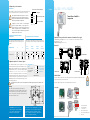
Connections
1. Switch 1 (S1)
2. Switch 2 (S2)
3. LCC-S software connection
4. Output terminal block
5. Power supply terminal block
6. Cable gland
12 6
5
4
3
Inside the front housing Removable front face Fixed back housing
41 mm
80 mm
112 mm
46 mm 90 mm
109 mm
Ø13 mm
90 mm
90 mm 46 mm
109 mm
135 mm
Ambient model
Remote model
Duct model
41 mm
80 mm
112 mm
46 mm 90 mm
109 mm
Ø13 mm
90 mm
90 mm 46 mm
109 mm
135 mm
90 mm
24.4 mm
29.5 mm
80 mm
Standard model
46 mm 90 mm
160 mm
80 mm
109 mm
(1) Ambient model / (2) Duct, remote and standard model.
1
6
3
5
4
(standard model)
For TH 110-AOS, TH 110-ANS, TH 110-AOD, TH 100-AND, TH 110-AOA, TH 110-ANA TH 110-ANES, TH 110-AOES models with
output 0-10 V - active:
For TH 110-POS, TH 110-PNS, TH 110-POD, TH 110-PND, TH 110-POA, TH 110-PNA, TH 110-PNES models
with output 4-20 mA - passive:
1 2 3 4 5 6 7
+ - + - +
type passif
VV
+
-Alimentation 24 Vdc
ou
VT GND VRH VT GND VRH
1 2 3 4 5 6 7
N L
6 7
ou
automate type passif
+ - + - +
++ -
++ -
VV
Alimentation
24 Vdc
Alimentation 24 Vac
Classe II
+-
L
L
N
N
A
+
+
+
+
-
-
-
-
1 2 3 4 5 6 7
- +- +
Alimentation
16-30 Vdc ou
IRH VdcIT Vdc
1 2 3 4 5 6 7
- +- +
IRH VdcIT Vdc
type actiftype passif
A
+-
A
+-
1 2 3 4 5 6 7
+ - + - +
type passif
VV
Alimentation 24 Vdc
++ -
16-30 Vdc 16-30 Vdc
Alimentation 16-30 Vdc
A
régulateur
ou automate
type passif
1 2 3 4 5 6 7
+ - + - +
Regulador/PLC/BMS tipo PASIVO
VV
+
-Alimentación 24 Vdc
o
VT GND VRH VT GND VRH
1 2 3 4 5 6 7
N L
6 7
o
+ - + - +
++ -
++ -
VV
Alimentación
24 Vdc
Alimentación 24 Vac
Class II
+-
L
L
N
N
A
+
+
+
+
-
-
-
-
1 2 3 4 5 6 7
- +- +
Alimentación
16-30 Vdc o
IRH VdcIT Vdc
1 2 3 4 5 6 7
- +- +
IRH VdcIT Vdc
Display/regulador/PLC/BMS tipo ACTIVODisplay/regulador/PLC/BMS tipo PASSIVO
A
+-
A
+-
1 2 3 4 5 6 7
+ - + - +
Regulador/PLC/BMS tipo PASIVO
VV
Alimentación 24 Vac
Class II
++ -
16-30 Vdc 16-30 Vdc
Alimentación 16-30 Vdc
A
Display/regu-
lador/PLC/BMS
tipo PASIVO
4 hilos
4 hilos
Display/regulador/PLC/BMS
tipo PASIVO
3 hilos
3 hilos
3 hilos
2 hilos
2 hilos
2 hilos
2 hilos
1 2 3 4 5 6 7
+ - + - +
VV
+
-Power supply 24 Vdc
or
VT GND VRH VT GND VRH
1 2 3 4 5 6 7
N L
6 7
or
+ - + - +
++ -
++ -
VV
Power supply
24 Vdc
Power supply 24 Vac
Class II
+-
L
L
N
N
A
+
+
+
+
-
-
-
-
1 2 3 4 5 6 7
- +- +
Power supply
16-30 Vdc or
IRH VdcIT Vdc
1 2 3 4 5 6 7
- +- +
IRH VdcIT Vdc
A
+-
A
+-
1 2 3 4 5 6 7
+ - + - +
VV
Power supply 24 Vdc
++ -
16-30 Vdc 16-30 Vdc
Power supply 16-30 Vdc
A
Display/regulator/PLC
passive type
4 wires
3 wires
2 wires
4 wires 3 wires
2 wires 2 wires 2 wires
Display/regulator/PLC passive type
Display/regulator/PLC passive type
Display/regulator/PLC passive type
Display/
regulator/PLC
passive type
Display/regulator/PLC active type
3 wires
1 2 3 4 5 6 7
+ - + - +
VV
+
-Alimentazione 24 Vdc
o
VT GND VRH VT GND VRH
1 2 3 4 5 6 7
N L
6 7
o
+ - + - +
++ -
++ -
VV
Alimentazione
24 Vdc
Alimentazione 24 Vac
Class II
+-
L
L
N
N
A
+
+
+
+
-
-
-
-
1 2 3 4 5 6 7
- +- +
Alimentazione
16-30 Vdc o
IRH VdcIT Vdc
1 2 3 4 5 6 7
- +- +
IRH VdcIT Vdc
A
+-
A
+-
1 2 3 4 5 6 7
+ - + - +
VV
Alimentazione 24 Vdc
++ -
16-30 Vdc 16-30 Vdc
Alimentazione16-30 Vdc
A
Display regolatore o
PLC/BMS tipo passivo
4 li
3 li
2 li
4 li 3 li
2 li 2 li 2 li
Display regolatore o PLC/BMS tipo passivo
Display regolatore o PLC/BMS tipo passivo
Display regolatore o PLC/BMS tipo passivo
Display
regolatore o
PLC/BMS tipo
passivo
Display regolatore o PLC/BMS tipo attivo
3 li

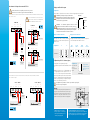
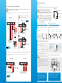
Settings and use of the transmitter
Conguration
Off On
Active switch
Unit setting
Output setting
On-off switch
1
2
3
4
It is possible to set the measuring ranges and the unit of the instrument either
by switch and/or via software.
To congure the transmitter, it must not be energized. Then, you
can make the settings required, with the DIP switches (as shown
on the drawing below).When the transmitter is congured, you can
power it up.
Please follow carefully the combinations beside with the DIP switch.
If the combination is wrongly done, the following message will
appear on the display of the transmitter “CONF ERROR”. In that
case, you will have to unplug the transmitter, place the DIP switches
correctly, and then power the transmitter up.
Units setting – active switch Outputs setting – active switch
To set a unit of measurement, put the on-off
switch 4 of the units as shown below.
Congurations °C °F From 0
to +50 °C
From -20
to +80 °C
From -50
to +50 °C
From 0 to
+100 °C
Combinations
To set an output, put the on-off switches 1, 2 and 3 of the
measuring ranges as shown below.
1
2
3
4
1
2
3
4
1
2
3
4
1
2
3
4
1
2
3
4
1
2
3
4
1
2
3
4
Conguration via LCC-S software (option)
It is possible to congure intermediate ranges, an offset...
Example: for a 0-100 °C transmitter, minimum delta is 20 °C.
The instrument can be congured from 0 to +20 °C or from
-10 to +10 °C. In order to compensate a possible drift of the
sensor, it is possible to add an offset to the displayed value
by the TH 110 transmitter: it shows 48% RH, a standard
instrument shows 45% RH. It is then possible, via the
software, to integrate an offset of -3 to the displayed value by
the TH 110 instrument.
The conguration of the parameters can be done either with the DIP switch or via software (you can not
combine both solutions).
Mounting
To mount the transmitter, mount the ABS plate on the wall
(drilling: Ø 6 mm, screws and pins are supplied).
Insert the transmitter on the xing plate (see A on the drawing beside).
Rotate the housing in clockwise direction until you hear a “click” which
conrms that the transmitter is correctly installed.
7.5 mm
8 mm
4.5 mm
40 mm
50 mm
68 mm
75 mm
37.5 mm
23.75 mm
14 mm
A
A
A
A
Maintenance: please avoid any aggressive
solvent. Please protect the transmitter
and its probes from any cleaning product
containing formalin, that may be used for
cleaning rooms or ducts.
Precautions for use: please always use the device
in accordance with its intended use and within
parameters described in the technical features in order
not to compromise the protection ensured by the
device.
Français Guide rapide
Transmetteur d'humidité
et de température
Température d'utilisation, protection de l'instrument et information stockage
Conditions d'utilisation (°C/%RH/m): de -10 à +50 °C. En condition de non condensation. De 0 à 2000 m.
Protection: IP65(2) ou IP20(1)
Température de stockage: de -10 à +70 °C.
Dimensions
Symboles utilisés
Pour votre sécurité et an d’éviter tout endommagement de l’appareil, veuillez suivre la procédure décrite
dans ce document et lire attentivement les notes précédées du symbole suivant :
Le symbole suivant sera également utilisé dans ce document. Veuillez lire attentivement les notes
d’informations indiquées après ce symbole.
Connectiques
12 6
5
4
3
Intérieur de la coque avant Face avant mobile Boîter arrière xe
41 mm
80 mm
112 mm
46 mm 90 mm
109 mm
Ø13 mm
90 mm
90 mm 46 mm
109 mm
135 mm
Modèle ambiant
Modèle déporté
Modèle arrière
41 mm
80 mm
112 mm
46 mm 90 mm
109 mm
Ø13 mm
90 mm
90 mm 46 mm
109 mm
135 mm
90 mm
24.4 mm
29.5 mm
80 mm
Modèle standard
46 mm 90 mm
160 mm
80 mm
109 mm
(1) Modèle ambiant / (2) Modèles arrière, déporté et standard
1
6
3
5
4
(modèle standard)
1. Switch 1 (S1)
2. Switch 2 (S2)
3. Connexion logiciel LCC-S
4. Bornier de sortie
5. Bornier d'alimentation
6. Presse-étoupe
1
2
3
4
Active switch (S1)
Please refer to the
user manual of the
LCC-S software
to make the
conguration.
Connect the cable
of the LCC-S to the
connection of the
transmitter.
PC conguration

Raccordements électriques suivant normes NFC15-100
Seul un technicien formé et qualié peut réaliser cette opération.
Pour réaliser le raccordement, l’appareil doit être HORS-TENSION.
Pour un raccordement 3 ls, la masse de la sortie et
la masse d’entrée doivent être reliées AVANT TOUTE
MISE SOUS TENSION. Voir schéma ci-dessous.
Pour les modèles TH 110-AOS, TH 110-ANS, TH 110-AOD, TH 100-AND, TH 110-AOA, TH 110-ANA TH 110-ANES, TH 110-AOES
avec sortie 0-10 V - actif :
1 2 3 4 5 6 7
+ - + - +
type passif
VV
+
-
Alimentation 24 Vdc
ou
VT GND VRH VT GND VRH
1 2 3 4 5 6 7
N L
6 7
ou
automate type passif
+ - + - +
++ -
++ -
VV
Alimentation
24 Vdc
Alimentation 24 Vac
Classe II
+-
L
L
N
N
A
+
+
+
+
-
-
-
-
1 2 3 4 5 6 7
- +- +
Alimentation
16-30 Vdc
ou
IRH VdcIT Vdc
1 2 3 4 5 6 7
- +- +
IRH VdcIT Vdc
type actiftype passif
A
+-
A
+-
1 2 3 4 5 6 7
+ - + - +
type passif
VV
Alimentation 24 Vdc
++ -
16-30 Vdc 16-30 Vdc
Alimentation 16-30 Vdc
A
régulateur
ou automate
type passif
1 2 3 4 5 6 7
+ - + - +
Regulador/PLC/BMS tipo PASIVO
VV
+
-
Alimentación 24 Vdc
o
VT GND VRH VT GND VRH
1 2 3 4 5 6 7
N L
6 7
o
+ - + - +
++ -
++ -
VV
Alimentación
24 Vdc
Alimentación 24 Vac
Class II
+-
L
L
N
N
A
+
+
+
+
-
-
-
-
1 2 3 4 5 6 7
- +- +
Alimentación
16-30 Vdc
o
IRH VdcIT Vdc
1 2 3 4 5 6 7
- +- +
IRH VdcIT Vdc
Display/regulador/PLC/BMS tipo ACTIVODisplay/regulador/PLC/BMS tipo PASSIVO
A
+-
A
+-
1 2 3 4 5 6 7
+ - + - +
Regulador/PLC/BMS tipo PASIVO
VV
Alimentación 24 Vac
Class II
++ -
16-30 Vdc 16-30 Vdc
Alimentación 16-30 Vdc
A
Display/regu-
lador/PLC/BMS
tipo PASIVO
4 hilos
4 hilos
Display/regulador/PLC/BMS
tipo PASIVO
3 hilos
3 hilos
3 hilos
2 hilos
2 hilos
2 hilos
2 hilos
1 2 3 4 5 6 7
+ - + - +
VV
+
-
Power supply 24 Vdc
or
VT GND VRH VT GND VRH
1 2 3 4 5 6 7
N L
6 7
or
+ - + - +
++ -
++ -
VV
Power supply
24 Vdc
Power supply 24 Vac
Class II
+-
L
L
N
N
A
+
+
+
+
-
-
-
-
1 2 3 4 5 6 7
- +- +
Power supply
16-30 Vdc
or
IRH VdcIT Vdc
1 2 3 4 5 6 7
- +- +
IRH VdcIT Vdc
A
+-
A
+-
1 2 3 4 5 6 7
+ - + - +
VV
Power supply 24 Vdc
++ -
16-30 Vdc 16-30 Vdc
Power supply 16-30 Vdc
A
Display/regulator/PLC
passive type
4 wires
3 wires
2 wires
4 wires 3 wires
2 wires 2 wires 2 wires
Display/regulator/PLC passive type
Display/regulator/PLC passive type
Display/regulator/PLC passive type
Display/
regulator/PLC
passive type
Display/regulator/PLC active type
3 wires
1 2 3 4 5 6 7
+ - + - +
VV
+
-
Alimentazione 24 Vdc
o
VT GND VRH VT GND VRH
1 2 3 4 5 6 7
N L
6 7
o
+ - + - +
++ -
++ -
VV
Alimentazione
24 Vdc
Alimentazione 24 Vac
Class II
+-
L
L
N
N
A
+
+
+
+
-
-
-
-
1 2 3 4 5 6 7
- +- +
Alimentazione
16-30 Vdc
o
IRH VdcIT Vdc
1 2 3 4 5 6 7
- +- +
IRH VdcIT Vdc
A
+-
A
+-
1 2 3 4 5 6 7
+ - + - +
VV
Alimentazione 24 Vdc
++ -
16-30 Vdc 16-30 Vdc
Alimentazione16-30 Vdc
A
Display regolatore o
PLC/BMS tipo passivo
4 li
3 li
2 li
4 li 3 li
2 li 2 li 2 li
Display regolatore o PLC/BMS tipo passivo
Display regolatore o PLC/BMS tipo passivo
Display regolatore o PLC/BMS tipo passivo
Display
regolatore o
PLC/BMS tipo
passivo
Display regolatore o PLC/BMS tipo attivo
3 li
1 2 3 4 5 6 7
+ - + - +
type passif
VV
+
-Alimentation 24 Vdc
ou
VT GND VRH
VT GND VRH
1 2 3 4 5 6 7
N L
6 7
ou
automate type passif
+ - + - +
++ -
++ -
VV
Alimentation
24 Vdc
Alimentation 24 Vac
Classe II
+-
L
L
N
N
A
+
+
+
+
-
-
-
-
1 2 3 4 5 6 7
- +- +
Alimentation
16-30 Vdc ou
IRH VdcIT Vdc
1 2 3 4 5 6 7
- +- +
IRH VdcIT Vdc
type actiftype passif
A
+-
A
+-
1 2 3 4 5 6 7
+ - + - +
type passif
VV
Alimentation 24 Vdc
++ -
16-30 Vdc 16-30 Vdc
Alimentation 16-30 Vdc
A
régulateur
ou automate
type passif
1 2 3 4 5 6 7
+ - + - +
Regulador/PLC/BMS tipo PASIVO
VV
+
-Alimentación 24 Vdc
o
VT GND VRH VT GND VRH
1 2 3 4 5 6 7
N L
6 7
o
+ - + - +
++ -
++ -
VV
Alimentación
24 Vdc
Alimentación 24 Vac
Class II
+-
L
L
N
N
A
+
+
+
+
-
-
-
-
1 2 3 4 5 6 7
- +- +
Alimentación
16-30 Vdc o
IRH VdcIT Vdc
1 2 3 4 5 6 7
- +- +
IRH VdcIT Vdc
Display/regulador/PLC/BMS tipo ACTIVODisplay/regulador/PLC/BMS tipo PASSIVO
A
+-
A
+-
1 2 3 4 5 6 7
+ - + - +
Regulador/PLC/BMS tipo PASIVO
VV
Alimentación 24 Vac
Class II
++ -
16-30 Vdc 16-30 Vdc
Alimentación 16-30 Vdc
A
Display/regu-
lador/PLC/BMS
tipo PASIVO
4 hilos
4 hilos
Display/regulador/PLC/BMS
tipo PASIVO
3 hilos
3 hilos
3 hilos
2 hilos
2 hilos
2 hilos
2 hilos
1 2 3 4 5 6 7
+ - + - +
VV
+
-Power supply 24 Vdc
or
VT GND VRH VT GND VRH
1 2 3 4 5 6 7
N L
6 7
or
+ - + - +
++ -
++ -
VV
Power supply
24 Vdc
Power supply 24 Vac
Class II
+-
L
L
N
N
A
+
+
+
+
-
-
-
-
1 2 3 4 5 6 7
- +- +
Power supply
16-30 Vdc or
IRH VdcIT Vdc
1 2 3 4 5 6 7
- +- +
IRH VdcIT Vdc
A
+-
A
+-
1 2 3 4 5 6 7
+ - + - +
VV
Power supply 24 Vdc
++ -
16-30 Vdc 16-30 Vdc
Power supply 16-30 Vdc
A
Display/regulator/PLC
passive type
4 wires
3 wires
2 wires
4 wires 3 wires
2 wires 2 wires 2 wires
Display/regulator/PLC passive type
Display/regulator/PLC passive type
Display/regulator/PLC passive type
Display/
regulator/PLC
passive type
Display/regulator/PLC active type
3 wires
1 2 3 4 5 6 7
+ - + - +
VV
+
-Alimentazione 24 Vdc
o
VT GND VRH VT GND VRH
1 2 3 4 5 6 7
N L
6 7
o
+ - + - +
++ -
++ -
VV
Alimentazione
24 Vdc
Alimentazione 24 Vac
Class II
+-
L
L
N
N
A
+
+
+
+
-
-
-
-
1 2 3 4 5 6 7
- +- +
Alimentazione
16-30 Vdc o
IRH VdcIT Vdc
1 2 3 4 5 6 7
- +- +
IRH VdcIT Vdc
A
+-
A
+-
1 2 3 4 5 6 7
+ - + - +
VV
Alimentazione 24 Vdc
++ -
16-30 Vdc 16-30 Vdc
Alimentazione16-30 Vdc
A
Display regolatore o
PLC/BMS tipo passivo
4 li
3 li
2 li
4 li 3 li
2 li 2 li 2 li
Display regolatore o PLC/BMS tipo passivo
Display regolatore o PLC/BMS tipo passivo
Display regolatore o PLC/BMS tipo passivo
Display
regolatore o
PLC/BMS tipo
passivo
Display regolatore o PLC/BMS tipo attivo
3 li
Pour les modèles TH 110-POS, TH 110-PNS, TH 110-POD, TH 110-PND, TH 110-POA, TH 110-PNA, TH 110-PNES
avec sortie 4-20 mA - passif :
1 2 3 4 5 6 7
+ - + - +
type passif
VV
+
-Alimentation 24 Vdc
ou
VT GND VRH VT GND VRH
1 2 3 4 5 6 7
N L
6 7
ou
automate type passif
+ - + - +
++ -
++ -
VV
Alimentation
24 Vdc
Alimentation 24 Vac
Classe II
+-
L
L
N
N
A
+
+
+
+
-
-
-
-
1 2 3 4 5 6 7
- +- +
Alimentation
16-30 Vdc ou
IRH VdcIT Vdc
1 2 3 4 5 6 7
- +- +
IRH VdcIT Vdc
type actiftype passif
A
+-
A
+-
1 2 3 4 5 6 7
+ - + - +
type passif
VV
Alimentation 24 Vdc
++ -
16-30 Vdc 16-30 Vdc
Alimentation 16-30 Vdc
A
régulateur
ou automate
type passif
1 2 3 4 5 6 7
+ - + - +
Regulador/PLC/BMS tipo PASIVO
VV
+
-Alimentación 24 Vdc
o
VT GND VRH VT GND VRH
1 2 3 4 5 6 7
N L
6 7
o
+ - + - +
++ -
++ -
VV
Alimentación
24 Vdc
Alimentación 24 Vac
Class II
+-
L
L
N
N
A
+
+
+
+
-
-
-
-
1 2 3 4 5 6 7
- +- +
Alimentación
16-30 Vdc o
IRH VdcIT Vdc
1 2 3 4 5 6 7
- +- +
IRH VdcIT Vdc
Display/regulador/PLC/BMS tipo ACTIVODisplay/regulador/PLC/BMS tipo PASSIVO
A
+-
A
+-
1 2 3 4 5 6 7
+ - + - +
Regulador/PLC/BMS tipo PASIVO
VV
Alimentación 24 Vac
Class II
++ -
16-30 Vdc 16-30 Vdc
Alimentación 16-30 Vdc
A
Display/regu-
lador/PLC/BMS
tipo PASIVO
4 hilos
4 hilos
Display/regulador/PLC/BMS
tipo PASIVO
3 hilos
3 hilos
3 hilos
2 hilos
2 hilos
2 hilos
2 hilos
1 2 3 4 5 6 7
+ - + - +
VV
+
-Power supply 24 Vdc
or
VT GND VRH VT GND VRH
1 2 3 4 5 6 7
N L
6 7
or
+ - + - +
++ -
++ -
VV
Power supply
24 Vdc
Power supply 24 Vac
Class II
+-
L
L
N
N
A
+
+
+
+
-
-
-
-
1 2 3 4 5 6 7
- +- +
Power supply
16-30 Vdc or
IRH VdcIT Vdc
1 2 3 4 5 6 7
- +- +
IRH VdcIT Vdc
A
+-
A
+-
1 2 3 4 5 6 7
+ - + - +
VV
Power supply 24 Vdc
++ -
16-30 Vdc 16-30 Vdc
Power supply 16-30 Vdc
A
Display/regulator/PLC
passive type
4 wires
3 wires
2 wires
4 wires 3 wires
2 wires 2 wires 2 wires
Display/regulator/PLC passive type
Display/regulator/PLC passive type
Display/regulator/PLC passive type
Display/
regulator/PLC
passive type
Display/regulator/PLC active type
3 wires
1 2 3 4 5 6 7
+ - + - +
VV
+
-Alimentazione 24 Vdc
o
VT GND VRH VT GND VRH
1 2 3 4 5 6 7
N L
6 7
o
+ - + - +
++ -
++ -
VV
Alimentazione
24 Vdc
Alimentazione 24 Vac
Class II
+-
L
L
N
N
A
+
+
+
+
-
-
-
-
1 2 3 4 5 6 7
- +- +
Alimentazione
16-30 Vdc o
IRH VdcIT Vdc
1 2 3 4 5 6 7
- +- +
IRH VdcIT Vdc
A
+-
A
+-
1 2 3 4 5 6 7
+ - + - +
VV
Alimentazione 24 Vdc
++ -
16-30 Vdc 16-30 Vdc
Alimentazione16-30 Vdc
A
Display regolatore o
PLC/BMS tipo passivo
4 li
3 li
2 li
4 li 3 li
2 li 2 li 2 li
Display regolatore o PLC/BMS tipo passivo
Display regolatore o PLC/BMS tipo passivo
Display regolatore o PLC/BMS tipo passivo
Display
regolatore o
PLC/BMS tipo
passivo
Display regolatore o PLC/BMS tipo attivo
3 li
Réglages et utilisation du capteur
Conguration
Off On
Switch actif
Réglages des
unités
Réglage de
sortie
Interrupteur
1
2
3
4
Il est possitible de congurer les étendues de mesure et les unités de l’appareil par switch et/ou logiciel.
ATTENTION : pour congurer le capteur, le mettre HORS
TENSION puis procéder aux réglages souhaités en disposant les
interrupteurs comme décrit ci-contre. Remettre le capteur sous
tension une fois les réglages effectués.
ATTENTION : les combinaisons présentées doivent être bien
reproduites. Si une mauvaise combinaison est réalisée, le message «
CONF ERROR » apparaîtra lors de la mise sous tension du capteur. Il
faudra alors débrancher le capteur, l’ouvrir et disposer les interrupteurs
du switch correctement avant de le remettre sous tension.
Réglage des unités - switch actif Réglage de sortie - switch actif
Pour régler une unité de mesure, positionner
l’interrupteur 4 des unités comme indiqué dans le
tableau ci-dessus.
Congurations °C °F De 0
à +50 °C
De -20
à +80 °C
De -50
à +50 °C
De 0
à +100 °C
Combinaisons
Pour régler une étendue de mesure, positionner les interrupteurs 1,
2 et 3 comme indiqué dans le tableau ci-dessous.
1
2
3
4
1
2
3
4
1
2
3
4
1
2
3
4
1
2
3
4
1
2
3
4
1
2
3
4
Conguration logiciel LCC-S software (option)
Le logiciel permet une conguration plus souple.
Il est possible de congurer des échelles intermédiaires, un offset
etc.
Exemple : pour un capteur 0-100 °C, le delta minimum est de
20°C. L’appareil pourra donc être conguré de 0 à +20 °C ou
de -10 à +10 °C. An de compenser une dérive éventuelle du
capteur, il est possible d’ajouter un offset à la valeur afchée
par le TH110: il indique 48% HR, un appareil étalon indique
45 %RH. Il est alors possible, grâce au logiciel, d’intégrer un
offset de -3 à la valeur afchée par le TH 110.
La conguration des paramètres s’effectue soit par switch soit par logiciel.
Les deux ne sont pas compatibles.
1
2
3
4
Switch actif (S1)
Pour procéder à la
conguration de votre
appareil, voir la notice
du LCC-S.
Conguration PC
Raccorder le câble
du LCC-S
à la connexion du
capteur.
Entretien : éviter tous les produits
ménagers agressifs. Lors du nettoyage
à base de produits formolés (pièces ou
conduits), protéger l’appareil.
Précautions d'utilisation : veillez à toujours utiliser
l’appareil conformément à l’usage prévu et dans les limites des
paramètres décrits dans les caractéristiques techniques an de
ne pas compromettre la protection assurée par l’appareil.
Montage
Pour réaliser le montage mural, xer la plaque ABS au mur
(perçage Ø 6 mm, vis et chevilles fournies). Insérer le capteur
dans la plaque de xation (aux points A sur le schéma) en
l’inclinant à 30°. Faire pivoter le boîtier dans le sens des
aiguilles d’une montre jusqu’à l’obtention d’un clipage ferme.
7.5 mm
8 mm
4.5 mm
40 mm
50 mm
68 mm
75 mm
37.5 mm
23.75 mm
14 mm
A
A
A
A

Español Guía rápida
Transmisores de humedad
relativa y temperatura
Temperatura de uso, índice de protección de los instrumentos y informaciones para almacenamiento
Condiciones de uso (°C/%RH/m) : de -10 a +50 °C; sin condensación. De 0 a 2000 m.
Índice de protección : IP65(2) o IP20(1)
Temperatura de almacenamiento : de -10 a +70 °C.
Dimensiones
Símbolos utilizados
Por su seguridad y para evitar daños en el dispositivo, siga el procedimiento descrito en el presente
documento y lea atentamente las notas precedidas del siguiente símbolo:
El siguiente símbolo también se utiliza en el presente documento. Lea atentamente las notas informativas
indicadas tras este símbolo.
Conexiones
1
2
6
5
4
3
Interior de la parte frontal Parte frontal extraible Parte trasera ja
41 mm
80 mm
112 mm
46 mm 90 mm
109 mm
Ø13 mm
90 mm
90 mm 46 mm
109 mm
135 mm
Modelo ambiental
41 mm
80 mm
112 mm
46 mm 90 mm
109 mm
Ø13 mm
90 mm
90 mm 46 mm
109 mm
135 mm
90 mm
24.4 mm
29.5 mm
80 mm
Modelo estándar
46 mm 90 mm
160 mm
80 mm
109 mm
(1) Modelo ambiental / (2) Modelos posterior, a distancia y estándar.
1
6
3
5
4
(modelo estándar)
Modelo a distancia
Model posterior
1. Bloques de microinterruptores activo (S1)
2. Bloques de microinterruptores inactivo
3. Conexión LCC-S
4. Salida de señal
5. Bornes de alimentación
6. Prensa estopa
Conexiones eléctricas según la norma NFC15-100
La conexión debe ser realizada por un técnico cualicado. Mientras se realizan las conexiones, el
transmisor debe estar sin alimentación. La presencia de un interruptor o interruptor automático antes
del dispositivo es obligatoria.
EN LA CONEXIÓN A 3 HILOS, la interconexión entre
las tomas a tierra (GND) de salida de señal y de
alimentación debe realizarse antes de alimentar el
equipo.
Para los modelos TH 110-AOS, TH 110-ANS, TH 110-AOD, TH 100-AND, TH 110-AOA, TH 110-ANA TH 110-ANES y
TH 110-AOES, activo 0-10 V:
Para los modelos TH 110-POS, TH 110-PNS, TH 110-POD, TH 110-PND, TH 110-POA, TH 110-PN, y TH 110-PNES,
lazo pasivo 4-20 mA :
1 2 3 4 5 6 7
+ - + - +
type passif
VV
+
-Alimentation 24 Vdc
ou
VT GND VRH VT GND VRH
1 2 3 4 5 6 7
N L
6 7
ou
automate type passif
+ - + - +
++ -
++ -
VV
Alimentation
24 Vdc
Alimentation 24 Vac
Classe II
+-
L
L
N
N
A
+
+
+
+
-
-
-
-
1 2 3 4 5 6 7
- +- +
Alimentation
16-30 Vdc ou
IRH VdcIT Vdc
1 2 3 4 5 6 7
- +- +
IRH VdcIT Vdc
type actiftype passif
A
+-
A
+-
1 2 3 4 5 6 7
+ - + - +
type passif
VV
Alimentation 24 Vdc
++ -
16-30 Vdc 16-30 Vdc
Alimentation 16-30 Vdc
A
régulateur
ou automate
type passif
1 2 3 4 5 6 7
+ - + - +
Regulador/PLC/BMS tipo PASIVO
VV
+
-Alimentación 24 Vdc
o
VT GND VRH
VT GND VRH
1 2 3 4 5 6 7
N L
6 7
o
+ - + - +
++ -
++ -
VV
Alimentación
24 Vdc
Alimentación 24 Vac
Class II
+-
L
L
N
N
A
+
+
+
+
-
-
-
-
1 2 3 4 5 6 7
- +- +
Alimentación
16-30 Vdc o
IRH VdcIT Vdc
1 2 3 4 5 6 7
- +- +
IRH VdcIT Vdc
Display/regulador/PLC/BMS tipo ACTIVODisplay/regulador/PLC/BMS tipo PASSIVO
A
+-
A
+-
1 2 3 4 5 6 7
+ - + - +
Regulador/PLC/BMS tipo PASIVO
VV
Alimentación 24 Vac
Class II
++ -
16-30 Vdc 16-30 Vdc
Alimentación 16-30 Vdc
A
Display/regu-
lador/PLC/BMS
tipo PASIVO
4 hilos
4 hilos
Display/regulador/PLC/BMS
tipo PASIVO
3 hilos
3 hilos
3 hilos
2 hilos
2 hilos
2 hilos
2 hilos
1 2 3 4 5 6 7
+ - + - +
VV
+
-Power supply 24 Vdc
or
VT GND VRH VT GND VRH
1 2 3 4 5 6 7
N L
6 7
or
+ - + - +
++ -
++ -
VV
Power supply
24 Vdc
Power supply 24 Vac
Class II
+-
L
L
N
N
A
+
+
+
+
-
-
-
-
1 2 3 4 5 6 7
- +- +
Power supply
16-30 Vdc or
IRH VdcIT Vdc
1 2 3 4 5 6 7
- +- +
IRH VdcIT Vdc
A
+-
A
+-
1 2 3 4 5 6 7
+ - + - +
VV
Power supply 24 Vdc
++ -
16-30 Vdc 16-30 Vdc
Power supply 16-30 Vdc
A
Display/regulator/PLC
passive type
4 wires
3 wires
2 wires
4 wires 3 wires
2 wires 2 wires 2 wires
Display/regulator/PLC passive type
Display/regulator/PLC passive type
Display/regulator/PLC passive type
Display/
regulator/PLC
passive type
Display/regulator/PLC active type
3 wires
1 2 3 4 5 6 7
+ - + - +
VV
+
-Alimentazione 24 Vdc
o
VT GND VRH VT GND VRH
1 2 3 4 5 6 7
N L
6 7
o
+ - + - +
++ -
++ -
VV
Alimentazione
24 Vdc
Alimentazione 24 Vac
Class II
+-
L
L
N
N
A
+
+
+
+
-
-
-
-
1 2 3 4 5 6 7
- +- +
Alimentazione
16-30 Vdc o
IRH VdcIT Vdc
1 2 3 4 5 6 7
- +- +
IRH VdcIT Vdc
A
+-
A
+-
1 2 3 4 5 6 7
+ - + - +
VV
Alimentazione 24 Vdc
++ -
16-30 Vdc 16-30 Vdc
Alimentazione16-30 Vdc
A
Display regolatore o
PLC/BMS tipo passivo
4 li
3 li
2 li
4 li 3 li
2 li 2 li 2 li
Display regolatore o PLC/BMS tipo passivo
Display regolatore o PLC/BMS tipo passivo
Display regolatore o PLC/BMS tipo passivo
Display
regolatore o
PLC/BMS tipo
passivo
Display regolatore o PLC/BMS tipo attivo
3 li
1 2 3 4 5 6 7
+ - + - +
type passif
VV
+
-Alimentation 24 Vdc
ou
VT GND VRH VT GND VRH
1 2 3 4 5 6 7
N L
6 7
ou
automate type passif
+ - + - +
++ -
++ -
VV
Alimentation
24 Vdc
Alimentation 24 Vac
Classe II
+-
L
L
N
N
A
+
+
+
+
-
-
-
-
1 2 3 4 5 6 7
- +- +
Alimentation
16-30 Vdc ou
IRH VdcIT Vdc
1 2 3 4 5 6 7
- +- +
IRH VdcIT Vdc
type actiftype passif
A
+-
A
+-
1 2 3 4 5 6 7
+ - + - +
type passif
VV
Alimentation 24 Vdc
++ -
16-30 Vdc 16-30 Vdc
Alimentation 16-30 Vdc
A
régulateur
ou automate
type passif
1 2 3 4 5 6 7
+ - + - +
Regulador/PLC/BMS tipo PASIVO
VV
+
-Alimentación 24 Vdc
o
VT GND VRH VT GND VRH
1 2 3 4 5 6 7
N L
6 7
o
+ - + - +
++ -
++ -
VV
Alimentación
24 Vdc
Alimentación 24 Vac
Class II
+-
L
L
N
N
A
+
+
+
+
-
-
-
-
1 2 3 4 5 6 7
- +- +
Alimentación
16-30 Vdc o
IRH VdcIT Vdc
1 2 3 4 5 6 7
- +- +
IRH VdcIT Vdc
Display/regulador/PLC/BMS tipo ACTIVODisplay/regulador/PLC/BMS tipo PASSIVO
A
+-
A
+-
1 2 3 4 5 6 7
+ - + - +
Regulador/PLC/BMS tipo PASIVO
VV
Alimentación 24 Vac
Class II
++ -
16-30 Vdc 16-30 Vdc
Alimentación 16-30 Vdc
A
Display/regu-
lador/PLC/BMS
tipo PASIVO
4 hilos
4 hilos
Display/regulador/PLC/BMS
tipo PASIVO
3 hilos
3 hilos
3 hilos
2 hilos
2 hilos
2 hilos
2 hilos
1 2 3 4 5 6 7
+ - + - +
VV
+
-Power supply 24 Vdc
or
VT GND VRH VT GND VRH
1 2 3 4 5 6 7
N L
6 7
or
+ - + - +
++ -
++ -
VV
Power supply
24 Vdc
Power supply 24 Vac
Class II
+-
L
L
N
N
A
+
+
+
+
-
-
-
-
1 2 3 4 5 6 7
- +- +
Power supply
16-30 Vdc or
IRH VdcIT Vdc
1 2 3 4 5 6 7
- +- +
IRH VdcIT Vdc
A
+-
A
+-
1 2 3 4 5 6 7
+ - + - +
VV
Power supply 24 Vdc
++ -
16-30 Vdc 16-30 Vdc
Power supply 16-30 Vdc
A
Display/regulator/PLC
passive type
4 wires
3 wires
2 wires
4 wires 3 wires
2 wires 2 wires 2 wires
Display/regulator/PLC passive type
Display/regulator/PLC passive type
Display/regulator/PLC passive type
Display/
regulator/PLC
passive type
Display/regulator/PLC active type
3 wires
1 2 3 4 5 6 7
+ - + - +
VV
+
-Alimentazione 24 Vdc
o
VT GND VRH VT GND VRH
1 2 3 4 5 6 7
N L
6 7
o
+ - + - +
++ -
++ -
VV
Alimentazione
24 Vdc
Alimentazione 24 Vac
Class II
+-
L
L
N
N
A
+
+
+
+
-
-
-
-
1 2 3 4 5 6 7
- +- +
Alimentazione
16-30 Vdc o
IRH VdcIT Vdc
1 2 3 4 5 6 7
- +- +
IRH VdcIT Vdc
A
+-
A
+-
1 2 3 4 5 6 7
+ - + - +
VV
Alimentazione 24 Vdc
++ -
16-30 Vdc 16-30 Vdc
Alimentazione16-30 Vdc
A
Display regolatore o
PLC/BMS tipo passivo
4 li
3 li
2 li
4 li 3 li
2 li 2 li 2 li
Display regolatore o PLC/BMS tipo passivo
Display regolatore o PLC/BMS tipo passivo
Display regolatore o PLC/BMS tipo passivo
Display
regolatore o
PLC/BMS tipo
passivo
Display regolatore o PLC/BMS tipo attivo
3 li
(1) Modèle ambiental / (2) Modèles posterior, a distancia y estándar

Conguración y uso del transmisor
Conguración
Off On
Bloque derecho de microinterruptores
Ajuste de las unidades
Ajuste de la señal de salida
Interruptor
1
2
3
4
Puede realizar la conguración mediante los microinterruptores (bloque
derecho) o mediante ordenador con el programa LCC-S (opcional).
Para congurar el transmisor, debe proceder a colocar los
interruptores según se describe a continuación cuando el
equipo esté sin alimentación. Reestablezca la alimentación
una vez haya completado la conguración.
Compruebe la correcta selección de los interruptores
según los esquemas indicados. Si por algún error se
conectara uno de ellos de forma incorrecta aparecería en
pantalla el siguiente mensaje: “CONF ERROR”. En este
caso sería necesario quitar la alimentación y posicionar los
interruptores de la forma correcta.
Conguración de las unidades de medición
de temperatura Conguración del rango de temperatura
Para congurar la unidad de temperatura, colocar el
interruptor 4 del bloque derecho (activo) tal y como
se indica :
Conguraciones °C °F De 0
a +50 °C
De -20
a +80 °C
De -50
a +50 °C
De 0
a +100 °C
Combinaisons
Para ajustar la salida analógica, posicionar los interruptores 1,
2 y 3 del bloque derecho (activo) para la salida según de indica:
1
2
3
4
1
2
3
4
1
2
3
4
1
2
3
4
1
2
3
4
1
2
3
4
Conguration logiciel LCC-S software (option)
Una conguración exible gracias al programa LCC-S. Podrá
congurar usted mismo sus propias escalas intermedias, un offset...
Ejemplo: la diferencia mínima entre los valores mínimo y máximo
de temperatura debe ser de 20 ºC. Se puede, por ejemplo, congurar
la salida de -20 ºC a 0 ºC, de 0 ºC a 20 ºC, o de -10 ºC a 10 ºC.
Para acceder a la conguración por software, es necesario ajustar
los interruptores previamente como se indica en el gráco y conectar
el cable al conector especíco en la electrónica (ver en el apartado
CONEXIONES). Para proceder a la conguración del equipo, consulte
el manual del programa LCC-S.
La conguración debe realizarse a través de los interruptores DIP o mediante programa (no pueden combinarse ambos
métodos).
1
2
3
4
Switch activo (S1)
Consulte el manual
de uso del software
LCC-S para realizar
la conguración.
Conguración con
LCC-S
Conecte el cable del
LCC-S a la conexión
del transmisor.
Montaje
Para realizar el montaje mural, jar la placa de ABS en la
pared (suministrada con el equipo). Tornillería: Ø 6 mm (tornillos
y tacos suministrados). Colocar el equipo a la placa de jación y
rotar 30°. Hacer pivotar la caja en sentido de las agujas del reloj
hasta obtener una jación segura.
7.5 mm
8 mm
4.5 mm
40 mm
50 mm
68 mm
75 mm
37.5 mm
23.75 mm
14 mm
A
A
A
A
Mantenimiento: evite el contacto con
disolventes agresivos. Proteja el transmisor
y sus sondas de cualquier producto de
limpieza que contenga formalina.
Precauciones en el uso del dispositivo: use siempre
el dispositivo de acuerdo con la aplicación para la cual
está destinado y dentro de los parámetros descritos
en las características técnicas para no comprometer la
protección garantizada del dispositivo.
Italiano Guida menù rapido
Trasmettitore di umidità e
temperatura
Temperatura di uso, protezione dello strumento e informazione di stoccaggio
Condizioni di uso (°C/%RH/m) : da -10 a +50 °C. In condizione non condensante. Da 0 a 2000 m.
Protezione : IP65(2) o IP20(1)
Temperatura di stoccaggio : da -10 a +70 °C.
Dimensioni
Simboli utilizzati
Il seguente simbolo compare vicino a note relative alla sicurezza e per evitare danni al dispositivo. Seguire
la procedura descritta in questo manuale utente:
Il seguente simbolo compare vicino a note importanti relative al corretto uso.
Conessioni
12 6
5
4
3
Interno della parte fronrale Frontalino rimovibile Retro della custodia ssa
41 mm
80 mm
112 mm
46 mm 90 mm
109 mm
Ø13 mm
90 mm
90 mm 46 mm
109 mm
135 mm
Modello ambiente
Modello remoto
Modello condotto
41 mm
80 mm
112 mm
46 mm 90 mm
109 mm
Ø13 mm
90 mm
90 mm 46 mm
109 mm
135 mm
90 mm
24.4 mm
29.5 mm
80 mm
Modello standard
46 mm 90 mm
160 mm
80 mm
109 mm
(1) Modello ambiente / (2) Modelli condotto, remoto e standard
1
6
3
5
4
(modello standard)
1. Interruttore attivo (S1)
2. Interruttore inattivo
3. Connessione LCC-S
4. Blocco terminale output
5. Blocco terminale alimentazione
6. Passacavo

Connessioni elettriche - come da standard NFC15-100
Questa connessione deve essere eseguita da un tecnico qualicato.Per effettuare la connessione,
il trasmettitore non deve essere energizzato.
Per eseguire una connessione a 3 li, prima di
accendere il trasmettitore, connettere la presa input a
quella output. Vedere il disegno qui sotto.
Per i modelli TH 110-AOS, TH 110-ANS, TH 110-AOD, TH 100-AND, TH 110-AOA, TH 110-ANA TH 110-ANES, TH 110-AOES con
outuput 0-10 V - attivo :
Per i modelli TH 110-POS, TH 110-PNS, TH 110-POD, TH 110-PND, TH 110-POA, TH 110-PNA, TH 110-PNES con
output 4-20 mA - passivo :
1 2 3 4 5 6 7
+ - + - +
type passif
VV
+
-Alimentation 24 Vdc
ou
VT GND VRH VT GND VRH
1 2 3 4 5 6 7
N L
6 7
ou
automate type passif
+ - + - +
++ -
++ -
VV
Alimentation
24 Vdc
Alimentation 24 Vac
Classe II
+-
L
L
N
N
A
+
+
+
+
-
-
-
-
1 2 3 4 5 6 7
- +- +
Alimentation
16-30 Vdc ou
IRH VdcIT Vdc
1 2 3 4 5 6 7
- +- +
IRH VdcIT Vdc
type actiftype passif
A
+-
A
+-
1 2 3 4 5 6 7
+ - + - +
type passif
VV
Alimentation 24 Vdc
++ -
16-30 Vdc 16-30 Vdc
Alimentation 16-30 Vdc
A
régulateur
ou automate
type passif
1 2 3 4 5 6 7
+ - + - +
Regulador/PLC/BMS tipo PASIVO
VV
+
-Alimentación 24 Vdc
o
VT GND VRH VT GND VRH
1 2 3 4 5 6 7
N L
6 7
o
+ - + - +
++ -
++ -
VV
Alimentación
24 Vdc
Alimentación 24 Vac
Class II
+-
L
L
N
N
A
+
+
+
+
-
-
-
-
1 2 3 4 5 6 7
- +- +
Alimentación
16-30 Vdc o
IRH VdcIT Vdc
1 2 3 4 5 6 7
- +- +
IRH VdcIT Vdc
Display/regulador/PLC/BMS tipo ACTIVODisplay/regulador/PLC/BMS tipo PASSIVO
A
+-
A
+-
1 2 3 4 5 6 7
+ - + - +
Regulador/PLC/BMS tipo PASIVO
VV
Alimentación 24 Vac
Class II
++ -
16-30 Vdc 16-30 Vdc
Alimentación 16-30 Vdc
A
Display/regu-
lador/PLC/BMS
tipo PASIVO
4 hilos
4 hilos
Display/regulador/PLC/BMS
tipo PASIVO
3 hilos
3 hilos
3 hilos
2 hilos
2 hilos
2 hilos
2 hilos
1 2 3 4 5 6 7
+ - + - +
VV
+
-Power supply 24 Vdc
or
VT GND VRH VT GND VRH
1 2 3 4 5 6 7
N L
6 7
or
+ - + - +
++ -
++ -
VV
Power supply
24 Vdc
Power supply 24 Vac
Class II
+-
L
L
N
N
A
+
+
+
+
-
-
-
-
1 2 3 4 5 6 7
- +- +
Power supply
16-30 Vdc or
IRH VdcIT Vdc
1 2 3 4 5 6 7
- +- +
IRH VdcIT Vdc
A
+-
A
+-
1 2 3 4 5 6 7
+ - + - +
VV
Power supply 24 Vdc
++ -
16-30 Vdc 16-30 Vdc
Power supply 16-30 Vdc
A
Display/regulator/PLC
passive type
4 wires
3 wires
2 wires
4 wires 3 wires
2 wires 2 wires 2 wires
Display/regulator/PLC passive type
Display/regulator/PLC passive type
Display/regulator/PLC passive type
Display/
regulator/PLC
passive type
Display/regulator/PLC active type
3 wires
1 2 3 4 5 6 7
+ - + - +
VV
+
-Alimentazione 24 Vdc
o
VT GND VRH
VT GND VRH
1 2 3 4 5 6 7
N L
6 7
o
+ - + - +
++ -
++ -
VV
Alimentazione
24 Vdc
Alimentazione 24 Vac
Class II
+-
L
L
N
N
A
+
+
+
+
-
-
-
-
1 2 3 4 5 6 7
- +- +
Alimentazione
16-30 Vdc o
IRH VdcIT Vdc
1 2 3 4 5 6 7
- +- +
IRH VdcIT Vdc
A
+-
A
+-
1 2 3 4 5 6 7
+ - + - +
VV
Alimentazione 24 Vdc
++ -
16-30 Vdc 16-30 Vdc
Alimentazione16-30 Vdc
A
Display regolatore o
PLC/BMS tipo passivo
4 li
3 li
2 li
4 li
3 li
2 li 2 li 2 li
Display regolatore o PLC/BMS tipo passivo
Display regolatore o PLC/BMS tipo passivo
Display regolatore o PLC/BMS tipo passivo
Display
regolatore o
PLC/BMS tipo
passivo
Display regolatore o PLC/BMS tipo attivo
3 li
1 2 3 4 5 6 7
+ - + - +
type passif
VV
+
-Alimentation 24 Vdc
ou
VT GND VRH VT GND VRH
1 2 3 4 5 6 7
N L
6 7
ou
automate type passif
+ - + - +
++ -
++ -
VV
Alimentation
24 Vdc
Alimentation 24 Vac
Classe II
+-
L
L
N
N
A
+
+
+
+
-
-
-
-
1 2 3 4 5 6 7
- +- +
Alimentation
16-30 Vdc ou
IRH VdcIT Vdc
1 2 3 4 5 6 7
- +- +
IRH VdcIT Vdc
type actiftype passif
A
+-
A
+-
1 2 3 4 5 6 7
+ - + - +
type passif
VV
Alimentation 24 Vdc
++ -
16-30 Vdc 16-30 Vdc
Alimentation 16-30 Vdc
A
régulateur
ou automate
type passif
1 2 3 4 5 6 7
+ - + - +
Regulador/PLC/BMS tipo PASIVO
VV
+
-Alimentación 24 Vdc
o
VT GND VRH VT GND VRH
1 2 3 4 5 6 7
N L
6 7
o
+ - + - +
++ -
++ -
VV
Alimentación
24 Vdc
Alimentación 24 Vac
Class II
+-
L
L
N
N
A
+
+
+
+
-
-
-
-
1 2 3 4 5 6 7
- +- +
Alimentación
16-30 Vdc o
IRH VdcIT Vdc
1 2 3 4 5 6 7
- +- +
IRH VdcIT Vdc
Display/regulador/PLC/BMS tipo ACTIVODisplay/regulador/PLC/BMS tipo PASSIVO
A
+-
A
+-
1 2 3 4 5 6 7
+ - + - +
Regulador/PLC/BMS tipo PASIVO
VV
Alimentación 24 Vac
Class II
++ -
16-30 Vdc 16-30 Vdc
Alimentación 16-30 Vdc
A
Display/regu-
lador/PLC/BMS
tipo PASIVO
4 hilos
4 hilos
Display/regulador/PLC/BMS
tipo PASIVO
3 hilos
3 hilos
3 hilos
2 hilos
2 hilos
2 hilos
2 hilos
1 2 3 4 5 6 7
+ - + - +
VV
+
-Power supply 24 Vdc
or
VT GND VRH VT GND VRH
1 2 3 4 5 6 7
N L
6 7
or
+ - + - +
++ -
++ -
VV
Power supply
24 Vdc
Power supply 24 Vac
Class II
+-
L
L
N
N
A
+
+
+
+
-
-
-
-
1 2 3 4 5 6 7
- +- +
Power supply
16-30 Vdc or
IRH VdcIT Vdc
1 2 3 4 5 6 7
- +- +
IRH VdcIT Vdc
A
+-
A
+-
1 2 3 4 5 6 7
+ - + - +
VV
Power supply 24 Vdc
++ -
16-30 Vdc 16-30 Vdc
Power supply 16-30 Vdc
A
Display/regulator/PLC
passive type
4 wires
3 wires
2 wires
4 wires 3 wires
2 wires 2 wires 2 wires
Display/regulator/PLC passive type
Display/regulator/PLC passive type
Display/regulator/PLC passive type
Display/
regulator/PLC
passive type
Display/regulator/PLC active type
3 wires
1 2 3 4 5 6 7
+ - + - +
VV
+
-Alimentazione 24 Vdc
o
VT GND VRH VT GND VRH
1 2 3 4 5 6 7
N L
6 7
o
+ - + - +
++ -
++ -
VV
Alimentazione
24 Vdc
Alimentazione 24 Vac
Class II
+-
L
L
N
N
A
+
+
+
+
-
-
-
-
1 2 3 4 5 6 7
- +- +
Alimentazione
16-30 Vdc o
IRH VdcIT Vdc
1 2 3 4 5 6 7
- +- +
IRH VdcIT Vdc
A
+-
A
+-
1 2 3 4 5 6 7
+ - + - +
VV
Alimentazione 24 Vdc
++ -
16-30 Vdc 16-30 Vdc
Alimentazione16-30 Vdc
A
Display regolatore o
PLC/BMS tipo passivo
4 li
3 li
2 li
4 li 3 li
2 li 2 li 2 li
Display regolatore o PLC/BMS tipo passivo
Display regolatore o PLC/BMS tipo passivo
Display regolatore o PLC/BMS tipo passivo
Display
regolatore o
PLC/BMS tipo
passivo
Display regolatore o PLC/BMS tipo attivo
3 li
Impostazioni e uso del sensore
Congurazione
Off On
Interruttore attivo
Impostazione unità
Impostazione output
Interruttore on-off
1
2
3
4
E’ possibile impostare I range di misura e l’unità dello strumento con l’interruttore e/o tramite il software.
Per congurare il trasmettitore, quest’ultimo non deve essere
energizzato. E’ possibile quindi effettuare le impostazioni
necessarie grazie agli interruttori DIP come mostrato nei disegni
qui sotto. Quando il trasmettitore è congurato, è possibile
accenderlo.
Seguire attentamente le combinazioni con l’interruttore DIP.
Se la combinazione viene eseguita in modo sbagliato, apparirà
il seguente messaggio sul display del trasmettitore “CONF
ERROR”. In quel caso, dovrete scollegare il trasmettitore,
posizionare gli interruttori DIP in modo corretto, quindi
accendere il trasmettitore.
Impostazione unità - interruttore attivo Impostazioni output - switch attivo
Per impostare l’unità di misura, posizionare
l’interruttore on-off 4 delle unità come mostrato qui
sotto.
Congurazioni °C °F Da 0
a +50 °C
Da -20
a +80 °C
Da -50
a +50 °C
Da 0
a +100 °C
Combinazioni
Per impostare un output, posizionare gli interruttori on-off 1, 2 e
3 del range di misura come mostrato qui sotto.
1
2
3
4
1
2
3
4
1
2
3
4
1
2
3
4
1
2
3
4
1
2
3
4
Congurazione tramite il software LCC-S (opzione)
Congurazione facile e intuitiva con il software! E’ possibile
congurare i range intermedi e offset.
Esempio : per un trasmettitore 0-100 °C, il delta minimo è
20 °C. Lo strumento può essere congurato da 0 a +20 °C o
da -10 a +10 °C. Per compensare una possibile deviazione
del trasmettitore, è possibile aggiungere un offset al valore
visualizzato con lo strumento TH110: mostra 48%RH,
mentre uno strumento standard mostra 45%RH. E’ quindi
possibile, tramite il software, integrare un offset di -3 al
valore visualizzato con lo strumento TH 110.
La congurazione dei parametri può essere fatta sia con l’interruttore DIP o tramite il software. Non è
possibile combianre entrambe le soluzioni.
1
2
3
4
Interruttore attivo (S1)
Fare riferimento al
manuale d’uso di
LCC-S per eseguire
la congurazione.
Congurazione con PC
Connettere il cavo
del software LCC-S al
trasmettitore.
Montaggio
Per montare il trasmettitore, montare il retro di ABS al
muro (trapano: Ø 6 mm, viti e punte sono forniti).
Inserire il trasmettitore alla piastra ssa (vedere A sul
disegno qui a anco).
Ruotare la custodia in senso orario nché non udite un
“click” che confermerà che il trasmettitore è installato
correttamente.
7.5 mm
8 mm
4.5 mm
40 mm
50 mm
68 mm
75 mm
37.5 mm
23.75 mm
14 mm
A
A
A
A
Manutenzione: evitare i solventi aggressivi.
Proteggere il trasmettitore e le sonde da
qualsiasi tipo di prodotto per la pulizia che
contenga formalina e che potrebbe essere
utilizzato per la pulizia delle stanze o dei
condotti.
Precauzioni d'uso: utilizzare sempre il dispositivo nel
rispetto della sua destinazione d'uso e dei parametri
descritti nelle caratteristiche tecniche al ne di non
comprometterne la protezione dal dispositivo.


QSG – TH 110 – 07/10/22 – Non-contractual document – We reserve the right to modify the characteristics of our products without prior notice
www.sauermanngroup.com
Download the TH 110 data sheet
Télécharger la che technique du TH 110
Descargue la cha técnica del TH 110
Scarica la scheda tecnica del TH 110
Download the LCC-S software user manual
Télécharger la notice d'utilisation du logiciel LCC-S
Descargue el manual de usuario del software LCC-S
Scarica il manuale d'uso del software LCC-S
https://sauermann-en.custhelp.com
Customer service portal / Portail service clients
Portal de servicio al cliente / Portale servizio clienti
Use our Customer service portal to contact us
Utilisez notre Portail service clients pour nous contacter
Contacte con nosotros a través del Portal de servicio al cliente
Utilizzate il nostro Portale servizio clienti per contattarci
-
 1
1
-
 2
2
-
 3
3
-
 4
4
-
 5
5
-
 6
6
-
 7
7
-
 8
8
-
 9
9


in altre lingue
- English: sauermann TH 110 User guide
- français: sauermann TH 110 Mode d'emploi
- español: sauermann TH 110 Guía del usuario