Griven ACROBAT PE 575 Owners Manual & Instruction
- Categoria
- Stroboscopi
- Tipo
- Owners Manual & Instruction

Foglio di Istruzioni
Owner’s manual
ACROBAT PE 575
GR 0426 HSR/MSR/MSD 575 W
FI 0426 REV 1
04 Set 2001

INDICE
INDICE
Pag.
1.0 CONTENUTO DELL’IMBALLAGGIO 3
2.0 SICUREZZA 3
3.0 INSTALLAZIONE DEL PROIETTORE 3
3.1 Rimozione dei fermi di sicurezza per il trasporto 3
3.2 Montaggio della Lampada 4
3.3 Posizionamento del Proiettore 4
3.4 Fissaggio del proiettore 4
3.5 Collegamento elettrico 4
3.6 Connessione delle prese 5
4.0 USO DEL PROIETTORE 5
4.1 Lettura del display ed uso dei comandi 5
4.2 Opzioni 5
4.3 Funzionamento con DMX 6
4.4 Indicazione dei canali 7
5.0 FUNZIONAMENTO IN AUTOMATICO 7
6.0 RESET MEDIANTE CENTRALINA 8
7.0 MANUTENZIONE 8
7.1 Cambio gobo 8
7.2 Lubrificazione dei gobo rotanti 8
7.3 Lubrificazione del prisma rotante 9
7.4 Lubrificazione delle aste per l’autofocus 9
8.0 INFORMAZIONI TECNICHE 9
9.0 PARTI DI RICAMBIO 9
10.0 VALORI DMX 16
INDEX
INDEX
Page
1.0 PACKING 10
2.0 SAFETY 10
3.0 INSTALLATION 10
3.1 Movement arrest system removal 10
3.2 Fitting the lamp 11
3.3 Mounting position 11
3.4 Fixing plate 11
3.5 Electrical connection 11
3.6 XLR plugs connection 12
4.0 USE OF THE LANTERN 12
4.1 Display and control panel use 12
4.2 Options 12
4.3 DMX standard mode 13
4.4 Channel indication 14
5.0 AUTOMATIC MODE 14
6.0 RESET MODE ACCESS FROM A DMX CONTROLLER 15
7.0 MAINTENANCE 15
7.1 Gobo changing 15
7.2 Rotating gobos lubrification 15
7.3 Rotating prism lubrification 16
7.4 Auto focusing system lubrification 16
8.0 TECHNICAL INFORMATION 16
9.0 SPARE PARTS 16
10.0 DMX VALUES 16

1.0 CONTENUTO DELL’IMBALLAGGIO
Controllate attentamente il contenuto del cartone; in caso di danni al prodotto contattate il
vostro trasportatore. Nell’imballaggio del presente proiettore sono contenuti i seguenti prodotti:
n° 1 Foglio di Istruzioni;
n° 1 proiettore ACROBAT PE 575;
n° 2 spine XLR 3 poli (1 maschio+1 femmina);
n° 1 spina di alimentazione;
n°10 gobo in dotazione;
2.0 SICUREZZA
Prima di effettuare qualsiasi operazione sul proiettore, sconnettere fisicamente la linea di ali-
mentazione staccando la spina (ad esempio durante la sostituzione della lampada).
Questo proiettore è stato progettato per utilizzi in ambienti interni: nel caso venga utilizzato in
esterni, ACROBAT PE 575, deve essere posizionato al riparo dagli agenti atmosferici (ad
esempio sotto una tettoia, un porticato, ecc...).La temperatura ambiente massima non deve
superare i 50°C.
Attenzione: la temperatura della superficie esterna del proiettore può raggiungere 90°C.
Attenzione: lampada molto calda, prima della sostituzione attendete almeno 10 minuti.
Si raccomanda l’utilizzo della catena di sicurezza da fissare al proiettore ed alla struttura di
sospensione dello stesso per evitare la caduta accidentale del proiettore nel caso, poco probabi-
le, che il punto di fissaggio primario dovesse cedere.
3.0 INSTALLAZIONE DEL PROIETTORE
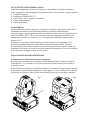
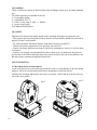
3.1 Rimozione dei fermi di sicurezza per il trasporto
Per evitare urti e movimenti che potrebbero causare danni al prodotto, durante il trasporto,
ACROBAT PE 575, è imballato con 2 fermi di sicurezza che assicurano la parte rotante al
resto del proiettore.
Prima di utilizzare il proiettore è quindi necessaria la loro rimozione. Eseguire questa operazio-
ne allentando 2 pomolini (indicati dalle frecce nelle figure 1 e 2) posti sulla parte cava del pro-
filo laterale, far scorrere i fermi fino alle estremità del profilo stesso e riavvitare i pomolini.
3
fig.1
fig.2

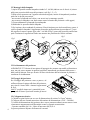
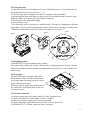
3.2 Montaggio della lampada
1) Aprite lo sportello cambio-lampada svitando le 2 viti M4 (indicate con le freccie A) situate
nella parte posteriore della testa del proiettore (vedi fig. 1, 2 e 3).
2) Dopo averla sgrassata con l’apposita salvietta detergente, inserite la lampada nel portalam-
pada con le dovute precauzioni:
- non toccate la lampada con le dita e con stracci unti o comunque sporchi;
- non scuotete la lampada e non fatela urtare contro la lamiera del proiettore o altri oggetti;
3) Fissate saldamente la lampada al portalampada.
4) Richiudete lo sportello cambio-lampada.
5) Può capitare, che accendendo il proiettore il fascio luminoso non sia ben uniforme, questo si
verifica quando la lampada è leggermente diversa da quella utilizzata in precedenza. E’ possi-
bile regolare la messa a punto: agire sulle 3 viti M4 (B fig.3) poste sullo sportello cambio-lam-
pada. Continuate la regolazione finche non ottenete una proiezione del fascio uniforme.
3.3 Posizionamento del proiettore
ACROBAT PE 575 è dotato di una piastra d’appoggio che permette una stabile collocazione a
terra, ma può essere montato in qualsiasi posizione, mantenendo una distanza dalla parete o
dalle pareti di almeno 50cm per favorire la libera circolazione dell’aria intorno al proiettore e
contenerne il riscaldamento.
3.4 Fissaggio del proiettore
Per il fissaggio del proiettore a terra, a parete, o al
soffitto utilizzate la piastra alla base del proiettore,
provvista di 6 inserti M10 e interassi rappresentati
in fig.4.
Nota:
E’ possibile rimuovere i gommini di soste-
gno prima di fissare il proiettore tramite gli inserti.
3.5 Collegamento elettrico
1) Cablate la spina fornita con un cavo di alimentazione di sezione 3x1.5mm
2
minimo.
2) Collegate alla rete facendo attenzione alla tensione di alimentazione (230V - 50/60Hz).
3) La linea di alimentazione del proiettore deve essere protetta mediante corretta messa a terra
e interruttore magnetotermico differenziale avente le seguenti caratteristiche:
- Corrente nominale (In) 10A - Valore d’intervento (Id) 0,03 A.
4) Questo proiettore dispone di rifasatore di corrente.
4
fig.1
fig.2
fig.3
fig.4
A
A
B
B
B

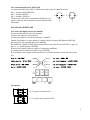
3.6 Connessione delle prese XLR 3 poli
La connessione delle prese XLR 3 poli dovrà avvenire come di seguito descritto:
pin 1> function GND (SHIELD);
pin 2> function SIGNAL - ;
pin 3> function SIGNAL + .
Verificate che i fili siano correttamente collegati nel con-
nettore e che essi non ne tocchino il guscio (utilizzare filo
schermato).
4.0 USO DEL PROIETTORE
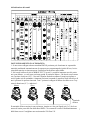
4.1 Lettura del display ed uso dei comandi
Il colore del led indica lo stato del proiettore.
La luce verde indica lo stato operativo.
La luce rossa indica lo stato di impostazione o modifica.
Quando il proiettore è in stato operativo il display indica il numero dell’indirizzo DMX del
proiettore (001 fino a quando non verrà cambiato).
Per modificare l’indirizzo DMX del proiettore premere una volta il tasto (SELECT) e agire sui
tasti (-), (+), quindi premere (ENTER).
Premerlo una seconda volta per scegliere l’opzione da modificare.
Per memorizzare la modifica premere il tasto (ENTER).
Se le modifiche non vengono confermate dopo 15 secondi il proiettore ritorna allo stato opera-
tivo.
4.2 Opzioni:
H = L’opzione è attivata (ON)
L = L’opzione non è attivata (OFF)
5

Tenendo premuto il tasto Enter per 5 secondi si visualizza il contatore della vita lampada.
Per resettare il contaore della lampada premere contemporaneamente (-), (+) ed (ENTER) fino
ad ottenere l’azzeramento del display.
Tenendo premuto il tasto Enter per 15 secondi si visualizza il contatore della vita del proietto-
re.
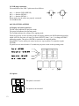
4.3 Funzionamento con DMX
Tutti i proiettori ACROBAT PE 575 che ricevono un segnale digitale da una centralina di con-
trollo devono avere correttamente settato il rispettivo display. Tenendo presente che ogni
proiettore ACROBAT PE 575 occupa da 9 a 14 canali (dipende dalle opzioni selezionate), a
seconda di quanti proiettori verranno collegati ad una centralina DMX, ciascuno dei proiettori,
per poter essere comandato singolarmente, dovrà essere settato come da tabella.
6
Indirizzo 9 Canali
Proiettore 1 0 0 1
Proiettore 2 0 1 0
Proiettore 3 0 1 9
Proiettore 4 0 2 8
Proiettore 5 0 3 7
Proiettore 6 0 4 6
Proiettore 7 0 5 5
Proiettore 8 0 6 4
Proiettore 9 0 7 3
Proiettore 10 0 8 2
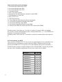
Numerazione delle opzioni sul display:
1= Inversione delle funzioni PAN/TILT
2= Inversione della direzione PAN
3= Inversione della direzione TILT
4= Automatico/Master
5= Pan e Tilt a bassa velocità
6= Impostazione del funzionamento automatico tramite DMX
7= Posizionamento su colori fissi
8= PAN e TILT 16 bit
9= TEST/Dimostrazione
10= Capovolgimento della direzione di lettura del display
11= Accensione/Spegnimento lampada tramite DMX
12= Attivazione Stand-By tramite DMX
13= Accensione/Spegnimento display tramite DMX
14= Disattivazione della rilevazione ottica PAN/TILT (Ruote ENCODER)

4.4 Indicazione dei canali
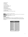
5.0 FUNZIONAMENTO IN AUTOMATICO
1. Se non viene collegato ad una centralina DMX il proiettore può funzionare in sequenziale
musicale cambiando automaticamente la sequenza pre-programmata dei giochi di luce; la rice-
zione della musica avviene attraverso il microfono incorporato nella scheda.
2. Nel caso di utilizzo di più ACROBAT PE 575 in serie, è possibile impostare uno dei proiet-
tori come Master , ovvero come proiettore-guida. Il proiettore Master - che dovrà essere settato
con l’opzione 4 attivata (“H”) - riceverà l’impulso musicale mediante il proprio microfono e
sarà in grado così di comandare i rimanenti proiettori ottenendo le sequenze degli effetti luce di
tutti i proiettori in perfetta sincronia. Tutti i proiettori collegati al Master dovranno avere l’op-
zione 4 disattivata (“L”) e indirizzo 1.
Il terminale di linea consiste in una resistenza, inserita tra i due pin Signal (pin 2 e 3) del con-
nettore di uscita posto alla fine della linea DMX. Ciò consente di evitare il malfunzionamento
della linea stessa. Consigliamo una resistenza da 120 Ohm 1W.
7
Master
Slave
Slave
Slave
Terminale
di linea

6.0 RESET MEDIANTE CENTRALINA
Per effettuare il reset da qualsiasi tipo di centralina DMX, è sufficiente lasciare il 2° canale
(Colour wheel) tra i valori 4 e 10 per almeno 6 secondi.
7.0 MANUTENZIONE
Tutti i proiettori richiedono una manutenzione regolare per assicurare la massima funzionalità e
la massima resa ottica. Seguite pertanto le seguenti istruzioni:
- pulite regolarmente le lenti e i dicroici poiché persino un sottilissimo strato di polvere può
ridurre in modo sostanziale la resa luminosa ed alterare la compattezza del fascio;
- sostituite le lenti e i dicroici se hanno subito danni visibili quali tagli, crepe e profondi graffi;
- sostituite la lampada se ha subito danni visibili o se si è deformata a causa del calore;
- controllate i collegamenti elettrici ed in particolare la messa a terra;
- sostituite tutte le parti eventualmente danneggiate;
-pulite periodicamente le ventole e tutte le feritoie di raffreddamento da eventuali oggetti estra-
nei entrati, o dalla polvere accumulatasi all’interno: per tali operazioni si consiglia l’uso di un
pennellino od eventualmente di un aspirapolvere; evitate l’uso di cacciaviti o altri oggetti acu-
minati che potrebbero danneggiare le ventole o altre parti del faro.
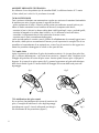
7.1 Cambio Gobo
Aprite il proiettore ed individuate il gobo che intendete sostituire. Se si tratta di un gobo fisso
(fig.1), sollevate delicatamente - con l’aiuto di un cacciavite - almeno 2 delle 3 linguette (A) di
fissaggio del gobo fino all’uscita del gobo stesso. Inserite quindi il nuovo gobo e ripiegate le
linguette. Se si tratta di un gobo rotante (fig.2), premete leggermente sul gobo nella direzione
della freccia finchè il gobo e l’anello elastico di fissaggio non escono dalla sede posta sull’
ingranaggio.
7.2 Lubrificazione dei gobo rotanti
Per un perfetto funzionamento del sistema di rotazione dei
gobo, si consiglia di lubrificare le sfere degli ingranaggi
periodicamente (ogni 2-4 mesi) utilizzando una siringa e
olio lubrificante ad alta prestazione (figura 3).
8
fig.1
fig.2
fig.3

7.3 Lubrificazione del prisma rotante
Per un perfetto funzionamento del sistema di rotazione del
prisma, si consiglia di lubrificare le sfere degli ingranaggi
periodicamente (ogni 2-4 mesi) utilizzando una siringa e
olio lubrificante ad alta prestazione (figura 1).
7.4 Lubrificazione delle aste autofocus
Per un perfetto funzionamento del sistema autofocus, si
consiglia di lubrificare periodicamente (ogni 2-4 mesi) le
aste su cui scorre la lente utilizzando una siringa e olio
lubrificante ad alta prestazione (figura 2).
8.0 INFORMAZIONI TECNICHE
9.0 PARTI DI RICAMBIO
Tutti i componenti del proiettore ACROBAT PE 575 sono disponibili come parti di ricambio e
la relativa vista esplosa è disponibile su richiesta.
9
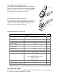
ACROBAT PE 575 W
Dimensioni max di ingombro
proiettore
L424 x P390 x H640
mm
Peso proiettore 28 Kg
Materiale della carcassa Polipropilene, Alluminio e Acciaio verniciato nero
Tensione nominale 230 V
Frequenza nominale 50/60 Hz
Corrente nominale 3,1 A
Potenza assorbita 700 VA
Lampada cons igliata HSR / MSR / MSD 575 W
Attacco GX 9,5
Sistema ottico
1 lente PC Ø 38
1 lente PC Ø 75
1 lente prismatica rotante Ø47 3 facce
Riflettore ellittico
Campo d'apertura 16°
Fus ibile 5x20 250V 10A
Temperatura ambiente massima 50 °C
Temperatura massima di esercizio 90 °C
fig.1
fig.2

1.0 PACKING
Check carefully the content of the box and in case of damage contact your forwarder immedia-
tely.
The following items are included in the box:
n° 1 instructions leaflet;
n° 1 ACROBAT PE 575;
n° 2 XLR 3 poles plugs (1 male + 1 female);
n° 1 power supply plug;
n°10 additional metal gobos.
2.0 SAFETY
Disconnect the lantern from mains supply before replacing the lamp or servicing the unit.
- This projector has been designed for use in interior: the unit shall be shielded or protected by
ingress of water if used outdoor.
- For safety operation, maximum ambient temperature must not exceed 50°C.
- Caution: the surface temperature of the projector can reach 90°C
- Caution: hot lamp! Make sure the lamp is cold before attempting to remove it: wait for about
10 minutes.
- Caution: it is strongly recommended that a safety-chain or wire is attached to this projector
and secured to the main mounting framework to arrest the fall of the unit in the unlikely event
that the primary mounting arrangement should fail.
3.0 INSTALLATION
3.1 Movement arrest system removal
A pan movement arrest system has been provided in order to avoid damages to the unit during
transport. Move the two arresting knobs before attempting to switch the unit on.
Unfasten the two knobs indicated by the arrows in pictures 1 and 2 and move them to the very
end of the outer profile;
10
pict.1
pict.2

3.2 Fitting the lamp
1) Open the lamp cover by loosening the 2 screws (indicated by arrows A) located on the rear
part of the head of the unit (see pictures 1, 2, 3).
2) Clean the lamp with a cleaning towel and fit it carefully in the lamp holder.
Avoid touching the lamp with fingers or dirty towels. Do not shake the lamp or make it clash
against the frame of the unit or any other internal component.
3) Fix the lamp to the lamp holder tightly.
4) Close the lamp cover.
5) The beam may not be even when you install the lamp. This may vary depending on different
lamps shape. For this reason lamp adjustment can be carried out by loosening or turning in the
3 M4 screws (indicated by arrows B) located on the lamp cover (see pict. 3).
3.3 Mounting position
ACROBAT PE 575 can be mounted in any position.
The support plate is fitted with 4 rubber feet that allow a steady position on the floor. The unit
should be installed at a minum distance from flammable objects of 0.5m, so as to make air cir-
culation easy.
3.4 Fixing plate
The base of the unit is provided with 6 M10
thread inserts to allow a steady installation on
every single kind of trussing system as well as
on the wall and on the floor.
Please note that the rubber feet can be removed
for a much more confortable fixing of the unit
by its proper insert.
3.5 Electrical connection
1) Cable the mains plug with a supply cable 3x1.5mm
2
(minimum size).
2) Connect the lantern to a mains supply of 230V - 50/60Hz.
3) Make sure the mains supply unit is correctly grounded.
The power line shall be provided with safety switch. (IN 10A, ID 0,03A).
4) ACROBAT PE 575 is fitted with power factor correction.
11
pict.1
pict.2
pict.3
pict.4
A
A
B
B
B

3.6 XLR plugs connection
The connection of the XLR 3 poles must be as follows:
pin 1---> function GND (SHIELD)
pin 2---> function SIGNAL -
pin 3---> function SIGNAL +
Please make sure the cables are properly connected.
Use shielded cable.
4.0 USE OF THE LANTERN
4.1 Display and control panel use
The led colour indicates the projector mode.
The green led indicates the operating mode.
The red light indicates the setting or the zapping mode.
When the projector is in the operating mode the display indicates the DMX addressing number,
which is 001 the first time you turn it on. Push (SELECT) then (-) or (+) to change the DMX
addressing number. Then press (ENTER) to memorise the required number.
Push (SELECT) twice when you want to activate or zap an option. To memorise it push
(ENTER).
If options are not entered within 15 seconds the projector returns to the operating mode.
4.2 Options
The option is activated.
The option is not activated.
12

Lamp life: Push (ENTER) for more then 5 seconds.
Lamp life reset:
Push (-), (+) and (ENTER) simultaneously until you get the zero setting of the
display to reset the lamp life meter.
Use meter:
Push (ENTER) for more than 15 seconds.
4.3 DMX standard mode
Make sure the display of the unit is correctly set. The ACROBAT PE 575 unit uses from a
minimum of 9 up to a maximum of 14 channels depending on the number of options selected.
The DMX addressing of more units accessed by a digital controller should be set as per follo-
wing diagram.
13
1= PAN/TILT Swap
2= PAN Reverse
3= TILT Reverse
4= Automatic/Master
5= PAN/TILT low speed
6= Automatic mode through DMX
7= Fixed - colour position
8= PAN/TILT 16 bit
9= TEST/DEMO mode
10= Display readout reversal
11= Lamp ON/OFF through DMX
12= Stand-By activation through DMX
13= Display ON/OFF
14=PAN/TILT positioning correction system ON/OFF
Address 9 Channels
Projector 1 0 0 1
Projector 2 0 1 0
Projector 3 0 1 9
Projector 4 0 2 8
Projector 5 0 3 7
Projector 6 0 4 6
Projector 7 0 5 5
Projector 8 0 6 4
Projector 9 0 7 3
Projector 10 0 8 2

4.4 Channels indication
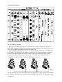
5.0 AUTOMATIC MODE
1. When the ACROBAT PE 575 unit is not connected to a DMX controller it can operate to
music while changing to different pre-programmed scenes sequences. The music beat is recei-
ved by the on-board microphone located on the main PCB.
2. More ACROBAT PE 575 units can be set to ‘SLAVE’option to follow the ‘MASTER’ unit
in synchrony. The ‘MASTER’ unit shall have option 4 set to (H); its microphone will follow
the music beat and will guide the rest of the units of the chain to the same rythm change
through the pre-programmed scenes. Option 4 of all ‘SLAVE’ units connected to the
‘MASTER’ one shall be set to (L) and their DMX address must be 1.
The line terminal is a resistor fitted between the 2 Signal Pins (2 and 3) at the end of the DMX
line. This is to avoid the defective functioning of the DMX line itself. A 120 Ohm/1W resistor
is suggested.
14
Master SlaveSlave
Slave
Line
terminal

6.0 RESET mode access from a DMX controller
Reset mode can be selected from any standard DMX controller by selecting the second channel
of the unit (Colour Wheel) and positioning between values 4 and 10 for more than 6 seconds.
7.0 MAINTENANCE
All lanterns require regular maintenance to ensure maximum performance and light output.
Please follow these instructions:
- clean lenses, mirrors and dichroics regularly, as even a thin layer of dust can reduce the light
output and scatter the beam;
- replace the lamp if it is damaged or deformed;
- carefully check the electrical connections, particularly the earth connection;
- replace lenses, mirrors and dichroic filters if they are visibly damaged;
- replace all damaged components
CAUTION: clean regularly the fans and the grids. Don't use screw drivers or sharp objects
which may damage the fans or other parts of the lantern.
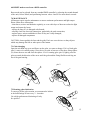
7.1 Gobo changing
Open the unit head top cover and figure out the gobo you want to change. If it is a fixed gobo
(pict.1) remove it carefully using a screw driver to open at least two of the three fixing splines
(A). Insert the new one and close the splines. If it is a rotating gobo (pict.2) lightly press the
gobo towarads the direction of the arrow until the gobo and the fixing flexible metal ring are
out of the gear housing.
7.2 Rotating gobos lubrication
To ensure a perfect gobo rotation we recommend to lubrica-
te the ball bearings at least every 2 - 4 months.
Use a high-performance lubricating oil only.
See picture 3.
15
pict.1
pict.2
pict.3

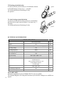
7.3 Rotating prism lubrication
To ensure a perfect prism rotation we recommend to lubrica-
te the ball bearings at least every 2 - 4 months.
Use a high-performance lubricating oil only.
See picture 1.
7.4 Auto focusing system lubrication
To ensure a perfect auto focusing system we recommend to
lubricate the two slide rods (see picture 2) at least every 2 -
4 months.
Use a high-performance lubricating oil only.
8.0 TECHNICAL INFORMATION
9.0 SPARE PARTS
All spares components for the ACROBAT PE 575 unit are available.
The exploded diagram, the wiring and electronic layouts and the catalogue are available on
request.
16
ACROBAT PE 575 W
Size
L424 x W390 x H640
mm
Weight 28 Kg
Body Galvanised Steel Body Aluminium and Polypropylene
Operating Voltage 230 V
Operating Frequence 50/60 Hz
Operating Amperage 3,1 A
Power Absorbed 700 VA
Suggested Lamp HSR / MSR / MSD 575 W
GX 9,5 Bas e
Optic System
1 PCX lens Ø 38
1 PCX lents Ø 75
3-facet rotating prismatic lens Ø47
Coated elliptical reflector
16° beam angle
Fuse 5x20 - 250V / 10A
Max Working Temperature 90 °C
Max Ambient Temperature 50 °C
pict.1
pict.2

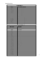
10.0 DMX VALUES
17
CHANNEL 1
DMX Level ROTOGOBO
0-127 360° indexed positioning
128-134
1° Rotation speed
135-141 2° Rotation speed
142-148 3° Rotation speed
149-155 4° Rotation speed
156-161 5° Rotation speed
162-168 6° Rotation speed
169-175 7° Rotation speed
176-182 8° Rotation speed
183-199 Stop
200-206 1° Reverse rotation speed
207-213 2° Reverse rotation speed
214-220 3° Reverse rotation speed
221-227 4° Reverse rotation speed
228-234 5° Reverse rotation speed
235-241 6° Reverse rotation speed
242-248 7° Reverse rotation speed
249-255 8° Reverse rotation speed
CHANNEL 2
DMX Level COLOURS
0-31 White
32-39 White - Deep purple
40-46 Deep purple
47-54 Deep purple - Yellow
55-61 Yellow
62-69 Yellow - Blue
70-76 Blue
77-84 Blue - Red
85-91 Red
92-99 Red - Green
100-107 Green
108-114 Green - Amber
115-122 Amber
123-129 Amber - Cyan
130-137 Cyan
138-144 Cyan - Magenta
145-152 Magenta
153-159 Magenta - Wood
160-167 Wood
168-175 Wood - White
176-183 1° Continuous rotation
184-191 2° Continuous rotation
192-199 3° Continuous rotation
200-207 4° Continuous rotation
208-215 5° Continuous rotation
216-223 6° Continuous rotation
224-231 7° Continuous rotation
232-239 8° Continuous rotation
240-255 9° Continuous rotation

18
CHANNEL 3
DMX Level GOBO CHANGE
0-36 1° Gobo
37-72 2° Gobo
73-109 3° Gobo
110-145
4° Gobo
146-182 5° Gobo
183-219
6° Gobo
220-255 7° Gobo
CHANNEL 4
DMX Level SHUTTER
0-15 Black-out
16-31 1° Strobing speed
32-47 2° Strobing speed
48-63 3° Strobing speed
64-79 4° Strobing speed
80-95 5° Strobing speed
96-111 6° Strobing speed
112-127 7° Strobing speed
128-143 8° Strobing speed
144-159 9° Strobing speed
160-175 10° Strobing speed
176-191
11° Strobing speed
192-207
12° Strobing speed
208-223
13° Strobing speed
224-239
14° Strobing speed
240-255
15° Strobing speed
CHANNEL 5
DMX Level PAN
0-255
PAN positioning
CHANNEL 7
DMX Level DIMMER
0-1 Open
2-240 Variable dimmering
241-255 Closed
CHANNEL 8
DMX Level FROST/PRISM
0-31 Open
32-63 Frost
64-127 Fixed prism
128-159 1° Rotating prism speed
160-191 2° Rotating prism speed
192-223 3° Rotating prism speed
224-255 Fixed prism
CHANNEL 6
DMX Level TILT
0-255 TILT positioning

19
CHANNEL 10
DMX Level LAMP/STAND-BY
0-127 Lamp ON
128-191 Stand-by (when option 11 H)
192-255
Lamp OFF
CHANNEL 11
DMX Level PAN 16 BIT
0-255 16 bit PAN (when option 8 H)
CHANNEL 12
DMX Level TILT 16 BIT
0-255 16 bit TILT (when option 8 H)
CHANNEL 13
DMX Level AUTOMATIC VIA DMX
0-192 Standard DMX
193-255 Automatic via DMX (when option 6 H)
CHANNEL 14
DMX Level DISPLAY
0-128 Display ON
129-255 Display OFF (when option 13 H)
CHANNEL 9
DMX Level FOCUS
0-255 Continuous focus progression

WORLD LIGHTING CHALLENGE
Professional Lighting Manufacturer
Via Bulgaria, 16 - 46042 CASTEL GOFFREDO (MN)
Telefono 0376/779483 - Fax 0376/779682 - 0376/779552
http://www.griven.com/ e-mail [email protected]
http://www.griven.it/ e-mail [email protected]
-
 1
1
-
 2
2
-
 3
3
-
 4
4
-
 5
5
-
 6
6
-
 7
7
-
 8
8
-
 9
9
-
 10
10
-
 11
11
-
 12
12
-
 13
13
-
 14
14
-
 15
15
-
 16
16
-
 17
17
-
 18
18
-
 19
19
-
 20
20


Griven ACROBAT PE 575 Owners Manual & Instruction
- Categoria
- Stroboscopi
- Tipo
- Owners Manual & Instruction
in altre lingue
- English: Griven ACROBAT PE 575
Documenti correlati
Altri documenti
-
ProLights RAZOR440 Manuale utente
-
-
-
-
-
-
-
-
-
 COEF MASTERSHOW 512 Istruzioni per l'uso
