
EnglishFrançaisItalianoHrvatskiDeutschEspañol
1
www.williamsjettenders.com
Owner’s
Handbook
www.williamsjettenders.com

EnglishFrançaisItalianoHrvatskiDeutschEspañol
2
www.williamsjettenders.com
EnglishFrançaisItalianoHrvatskiDeutschEspañol
3
www.williamsjettenders.com
32
Español Deutsch Hrvatski Italiano Français English
English
4–23
Français
24–43
Italiano
44–63
Hrvatski
64–83
Deutsch
84–103
Español
104–123
www.williamsjettenders.com
Owner’s Handbook
Owner’s Handbook

www.williamsjettenders.com
English
5
www.williamsjettenders.com
English
4
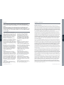
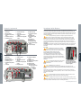
Thank You for Choosing a
Williams Dieseljet
This owner’s handbook has been compiled to help you operate your Dieseljet with safety and
pleasure. It contains details of the boat and equipment fitted, together with information on its
operation and maintenance. Please read it carefully, along with the Yanmar Engine manual,
and familiarise yourself with the boat before using it.
The Williams Dieseljet uses water jet propulsion. If this is your first boat or you are changing
to a type of boat you are not familiar with, for your own safety, please ensure that you obtain
handling and operating experience before assuming command of the boat. Your dealer,
national sailing federation or yacht club will be pleased to advise you of sea schools, or
competent instructors.
To take advantage of the Yanmar Engine Warranty, please remember to register your engine
online at www.yanmarmarine.com.
The Dieseljet range are high performance boats. Williams recommends a minimum
standard of RYA level 2 or ICC (International certificate of competency) is attained by
the operator prior to taking control of this boat. This manual assumes the operator has
acquired this standard of qualification and possesses knowledge of basic seamanship.
Please keep this handbook in a secure place and hand it to the new
owner if you sell the boat.
Hull Identification Number (HIN):
Safety
Williams Performance Tenders consider the safety of our customers of great importance. We
recommend people using our products exercise care and common sense, and comply with
the safety information within the Owner’s Handbook.
Always obey the safety labels fitted to the tender and replace should they become unreadable.
Be aware of local laws and restrictions and never use whilst under the influence of alcohol or
any substance which may affect your judgement.
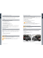
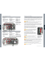
This symbol appears on a number of labels fitted to the Tender.
The symbol draws your attention to the message and refers you to the Owner’s
Handbook.
This safety alert symbol appears throughout the Owner’s Handbook and appears on
various labels fitted to the tender. It means attention, be alert, your safety is involved!
Please read and abide by the message that follows the safety alert symbol.
DANGER
Indicates a hazardous situation which, if not avoided, will result in death or serious injury.
WARNING
Indicates a hazardous situation which, if not avoided, could result in death or serious injury.
CAUTION
Indicates a hazardous situation which, if not avoided, could result in minor or moderate injury.
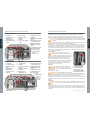
Classification
Category C – “inshore”: Craft designed for voyages in coastal waters, large bays, estuaries,
lakes and rivers, where conditions up to and including wind force 6 and significant wave
heights up to and including 2m may be experienced. These boats comply with ISO 6185-3.
The Hull Identification Number is located above jet nozzle on starboard side below platform
step: record it in the box opposite. The CE plate is located in the starboard footwell. The CE
plate is the certification to European Directive 94/25/CE.
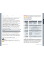
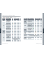
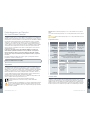
Engine Specifications
Dieseljet 445 & 505 Dieseljet 565 Dieseljet 625
Yanmar engine type
4JH4-HTE 110 HP 4BY2 150 HP 4BY2 180 HP
Maximum output
(Crankshaft)
80.9 kW (110 mhp) /
3200 rpm
110 kW (150 mhp) /
4000 rpm
132 kW (180 mhp) /
4000 rpm
Configuration
Water cooled, turbocharged, direct injection diesel
Displacement
1.995 L (122 cu in)
Cylinders
4 cylinders, 4 valves per cylinder
Cooling system
Fresh water cooling by centrifugal water pump and
rubber impeller sea water pump
Oil grade
15W40 0W40 – 10W30
API categories CD or higher
Coolant
Texaco Long Life
Coolant (LLC)
or Havoline
Extended life
antifreeze/coolant
30%-60%
Glysantin G48-24 engine coolant
Fuel
Diesel

EnglishFrançaisItalianoHrvatskiDeutschEspañol
6
www.williamsjettenders.com
7
www.williamsjettenders.com
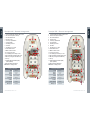
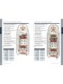
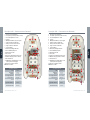
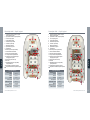
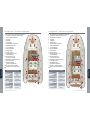
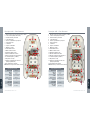
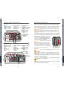
Dieseljet 505 – General Arrangement
1 Port and Starboard navigation light socket
2 Anchor locker (under cushion)
3 Shower fill and head
4 Storage locker
5 Passenger grab handles
6 Footwell drains
7 Boarding post bases
8 Fuel filler
9 Throttle/reverse control
10 Tube inflation valves
11 Main electrical isolator
12 Over pressure valves
13 12v auxiliary power/charge socket
14 All-round white navigation light socket
15 Mooring cleat (port and starboard)
16 Ski eye
17 Hull Identification Number (HIN)
(under platform)
18 Engine flushing attachment
@
Indicates seating position
General specifications
LOA
5.05 m
Beam
2.02 m
Height
1.1 m
Draft
0.27 – 0.42 m
Dry weight
820 kg
Seating
8
Fuel capacity
85 litres
Max speed
34 knots
English
Dieseljet 445 – General Arrangement
1 Port and Starboard navigation light socket
2 Anchor locker (under cushion)
3 Shower fill and head
4 Storage locker
5 Passenger grab handles
6 Footwell drains
7 Boarding post bases
8 Fuel filler
9 Throttle/reverse control
10 Tube inflation valves
11 Main electrical isolator
12 Over pressure valves
13 12v auxiliary power/charge socket
14 All-round white navigation light socket
15 Mooring cleat (port and starboard)
16 Ski eye
17 Hull Identification Number (HIN)
(under platform)
18 Engine flushing attachment
@
Indicates seating position
General specifications
LOA
4.45 m
Beam
2.02 m
Height
1.1 m
Draft
0.27 – 0.42 m
Dry weight
755 kg
Seating
7
Fuel capacity
50 litres
Max speed
35 knots
4
4
4
4
4
5
5
5
5
6
6
6
6
6
6
6
6
1
1
7
7
7
7
9
9
10
10
10
10
10
10
10
12
12
12
8
8
14
14
12
12
11
17
17
16
16
2 2
3
3
3
5
13
13
134 11
@
@
@
@
@
@
@
@
@
@
@
@
@
@ @
15
15
15
15
English
6
18
18
3

English
8
www.williamsjettenders.com
English
9
www.williamsjettenders.com
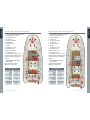
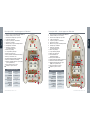
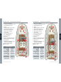
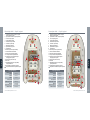
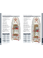
Dieseljet 565 – General Arrangement
1 Port and Starboard navigation light socket
2 Anchor locker (under cushion)
3 Shower fill and head
4 Storage locker
5 Passenger grab handles
6 Footwell drains
7 Boarding post bases
8 Fuel filler
9 Throttle/reverse control
10 Tube inflation valves
11 Main electrical isolator
12 Over pressure valves
13 12v auxiliary power/charge socket
14 All-round white navigation light socket
15 Mooring cleat (port and starboard)
16 Ski eye
17 Hull Identification Number (HIN)
(under platform)
18 Engine flushing attachment
@
Indicates seating position
General specifications
LOA
5.65 m
Beam
2.35 m
Height
1.16 m
Draft
0.35 – 0.5 m
Dry weight
1060 kg
Seating
9
Fuel capacity
105 litres
Max speed
36 knots
Dieseljet 625 – General Arrangement
1 Port and Starboard navigation light socket
2 Anchor locker (under cushion)
3 Shower fill and head
4 Storage locker
5 Passenger grab handles
6 Footwell drains
7 Boarding post bases
8 Fuel filler
9 Throttle/reverse control
10 Tube inflation valves
11 Main electrical isolator
12 Over pressure valves
13 12v auxiliary power/charge socket
14 All-round white navigation light socket
15 Mooring cleat (port and starboard)
16 Ski eye
17 Hull Identification Number (HIN)
(under platform)
18 Engine flushing attachment
@
Indicates seating position
General specifications
LOA
6.25 m
Beam
2.35 m
Height
1.16 m
Draft
0.35 – 0.5 m
Dry weight
1250 kg
Seating
11
Fuel capacity
120 litres
Max speed
36 knots
4 4
4
5
5
5
5
6
6
6
6
6
6
6
6
1 1
7
7
7
7
9
9
10 10
10 10
10
10 10
10
12 12
12
12
12
8
8
14
14
12
114
114
17
17
16
16
2
2
3
3
3
3
18
13
13
@
@
@
@
@
@ @
@@
@
@
@
@
@
@
@
@ @
15
15
15
15
4
4 4
@ @
18
5
5

www.williamsjettenders.com
English
11
www.williamsjettenders.com
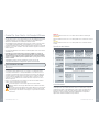
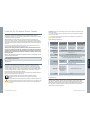
Controls and Instruments Operating Your Tender
This boat uses a water-jet propulsion system and has unique characteristics in steering. The
throttle produces thrust from the jet pump, the directional control is provided by opening the
throttle and turning the wheel in the direction of your turn. High thrust will turn the boat sharply;
low thrust will produce less turning force. There is no rudder, so while underway there is no
steering without thrust.
CAUTION. Maneuverability is severely restricted with reduced throttle or while
decelerating.
After running tender at high speeds it is important to allow engine to idle for a minimum of one
minute before switching off to allow turbo to cool.
If weed or debris gets caught in the jet unit during use cavitation can occur causing a decrease
in forward thrust. If there is any sign of debris or weeds etc. blocking the jet, remove the boat
from the water. Switch off battery isolator and remove all debris from around the jet unit.
DO NOT make repeated attempts to start a blocked or jammed tender as transmission
damage may result. In case of difficulty consult your Williams authorized dealer.
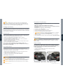
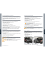
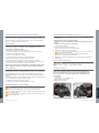
Recovery
CAUTION. Do not attempt to lift or recover the tender by the transom. Any stern-up
angle will cause water to enter the engine from
exhaust system and will result in serious engine damage.
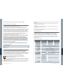
Manual Override of Reverse System
In the event that the reverse servo fails a manual override
facility is in place allowing forward drive of the tender. This
is by means of a lockable pin which can be removed from
its normal operating position and secured in the forward
bracket, as shown.
Mooring
CAUTION. Do not leave the Dieseljet moored
for extended periods as this may result in an
accumulation of marine growth and a loss of performance.
Beaching
CAUTION. DO NOT operate in less than 0.95m/3ft
of water as debris may enter the jet unit. DO NOT
drive Dieseljet onto beach. Stop engine before beaching to
prevent blockage to pump/engine cooling system.
After beaching move boat into deeper water and rock from side to side several times to
remove sand from intake area – failure to do so can cause excessive wear to jet unit.
Trim
CAUTION. Do not overload the boat beyond plated capacity. At all speeds be aware of
trim and keep weight evenly distributed.
General
CAUTION. Operate the boat with due care and at a speed appropriate to the sea
conditions. Be aware of local laws and restrictions. Always carry out a visual check of
the boat and its components prior to use. Adhere to the maintenance/service schedule.
Remove securing pin,
manually pull cable forward,
secure in forward bracket
English
10
Dieseljet 445 & 505
1 Rev counter
2 Speedometer
3 Coolant temperature
gauge
4 Oil pressure gauge
5 Fuel gauge
6 Warning light bank
7 VHF radio
8 Safety lanyard
9 Navigation light switch
10 Bilge blower switch
11 Bilge pump override
switch
12 Horn switch
13 Deck light switch
14 Shower switch
15 Throttle control
16 Chart Plotter
17 Engine Stop Button
18 Ignition Key
7
Dieseljet 565 & 625
1 Rev counter
2 Speedometer
3 Oil pressure gauge
4 Fuel gauge
5 Coolant temperature
gauge
6 Voltmeter
7 Music system
8 VHF radio
9 Safety lanyard
10 Navigation light switch
11 Bilge blower switch
12 Bilge pump override
switch
13 Horn switch
14 Deck light switch
15 Shower switch
16 Throttle control
17 Chart plotter
18 Oil pressure warning light
19 Ignition key
15
16
13
14
18
12
11
17
10
9
8
7
3
3
1
1
4
4
2
2
6
6
5
5
9
8
13
15
16
19
14
12
18
11
10
17

www.williamsjettenders.com
English
13
www.williamsjettenders.com
English
12
New Engine Break-in Period
The way your engine is operated during the first 50 hours of use will play a very significant role
in determining its ultimate performance and lifespan. The engine must be operated at suitable
speeds and power settings during the break-in period. Refer to Yanmar engine manuals for
information on running the engine during the first 50 hours of operation.
Fuelling
As part of its pre-delivery inspection your new Dieseljet has been fully tested and
drained of fuel. When refuelling use only Diesel fuel.
Do not refuel with engine running.•
Remove seat cushion to expose filler cap.•
Re-fuel in a ventilated area.•
Do not overfill the tank; be careful not to spill fuel.•
Tighten fuel cap securely after re-fuelling.•
Open engine hatch and inspect bilges after re-fuelling.•
The filler cap has an integral breather. Do NOT directly hose around the fuel filler area as •
water may enter the fuel tank.
Note: If engine is fitted with fuel primer/pump it may require pumping at first use or
when left for extended periods.
Before Use
Tube pressure will fluctuate with temperature. Inflate tubes in sequence to 250mB/3.6psi,
starting at rear valves. Failure to observe this will compromise the sea-keeping ability and
water tight integrity of the boat. Inflation valves are fitted with quarter-turn locks to enable rapid
deflation.
Set valves to shut and inflate tubes evenly, starting at rear/right, rear/left, then forward •
valves.
Check bilge for fuel or water contamination.•
Check engine cover latches are secure.•
Safety Check!
WARNING. ALWAYS attach yourself to the safety lanyard when engine is running.
Before setting off as a precautionary measure always test lanyard for its functionality by
pulling away from its seating – engine should always stop.
WARNING. NEVER operate the boat when bathers are using the boarding ladder, risk of
serious injury exists from reverse deflector.
WARNING. NEVER investigate engine bay with engine running or ignition on.
Starting Your Dieseljet
NEVER run engine if ambient temperature is excessively high or below -16°C (-5°F).•
NEVER attempt to switch off engine using battery isolator.•
Ensure boat is in a depth of at least 0.95m/3ft of water before attempting to start engine.•
Ensure all passengers are correctly seated.•
1 Turn on battery isolator.
2 Run bilge blower for 4 minutes.
3 Secure any loose ropes that could get sucked into jet unit.
4 Ensure shift lever is in neutral position.
5 Connect safety lanyard to switch.
WARNING. Personal injury may result if not attached.
6 Turn ignition key until engine starts, using heater function in cold conditions if required.
7 Test safety lanyard for correct functionality (see Safety Check! on page 12).
Warning Lamps/Alarms
CAUTION. Risk of engine damage. In the event that a warning lamp or buzzer activates
during use, STOP engine immediately, investigate cause and refer to engine manual.
Contact your authorized Williams Dealer.
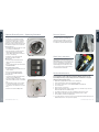
After Use
To prolong life it is very important to wash entire boat with fresh water after use and prior
to storage, especially the jet pump area. Failure to carry out fresh water washing will
significantly reduce the life of underwater components. Check anodes routinely.
Wash jet pump•
Check bilge of boat and dry any residual water•
Rinse footwells with fresh water•
Isolate battery•
1 Pump anodes 2 Hull anode 3 Reverse bucket anode
1
3
1
2

English
14
www.williamsjettenders.com
English
15
www.williamsjettenders.com
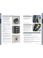
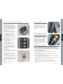
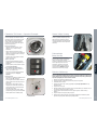
Flushing Procedure
To prolong engine life it is very important to flush engine of salt water after use and prior to
storage. Failure to carry out flushing will significantly reduce the life of engine components and
may invalidate warranty. DO NOT operate throttle out of water.
In addition it is advised to thoroughly wash with fresh water around the jet pump area to
remove all salt deposits after use.
CAUTION. Engine MUST be running
before water is connected. Risk of engine
flooding exists if water remains on after engine is
switched off.
1 Connect a fresh water hose fitted with the
male connector supplied with the tender to
the flushing attachment coupling fitted to
the tender. Push in outer ring when inserting
flushing connector.
2 Start engine and immediately turn on water
supply.
3 Run engine at idle for approximately 1 minute
to completely flush the open loop cooling
system.
4 Turn off water supply.
5 Allow the engine to run for no longer than 10
seconds to allow water to exit from the cooling
system, then turn off the engine. Remove hose
connector from flushing attachment.
6 Check bilge of boat and dry any residual water.
Remove footwell drain plugs.
Oil Level Check
The engine should be at operating temperature before an accurate level is indicated on
the dipstick.
The oil level should be between MIN and MAX on the dipstick.•
Use only the correct grade of oil (Diesel oil 15W40 or 0W40-10W30, refer to Engine •
Specification section and Yanmar Engine Manual.)
Do not overfill.•
CAUTION. Use of other than the specified engine oil may cause inner parts seizure or
early wear, leading to shortening the engine service life.
1
1 Flushing attachment
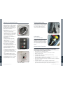
Electrical Panel
The tender’s electrical panel is located under the helm console. It mounts a number of
electrical components, including circuit breakers, the battery isolator, the thermal circuit
breaker and the 12 volt power socket.
WARNING. DAMAGE TO CHARGING CIRCUIT, LOSS OF REVERSE ACTUATOR &
SAFETY LANYARD WILL OCCUR IF ISOLATOR IS USED TO STOP ENGINE.
Cable Colour Codes
This chart sets out the corresponding colour to all cable printed abbreviations found on
the craft.
Code Colour Code Colour
BK Black VT Violet
GN Green RD Red
PK Pink GY Grey
LTGN Light green BE Blue
BN Brown WE White
OE Orange YW Yellow
Example: GN/YW will signify Green/Yellow

English
16
www.williamsjettenders.com
English
17
www.williamsjettenders.com
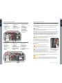
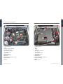
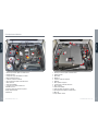
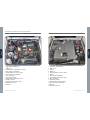
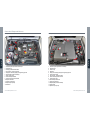
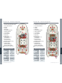
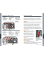
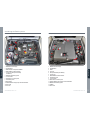
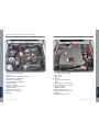
Boat System Arrangement
Dieseljet 445 & 505
Dieseljet 565 & 625
3
1
4
6
8
10
2
5
7
9
14
1
6
8
10
13
12
2
5
7
9
1 Coolant pressure cap
2 Oil fill
3 Fuel primer pump/secondary filter
4 Fuel/water separator filter
5 Fire extinguisher reset display
6 Coolant expansion tank
7 Seawater filter
8 Automatic greaser
9 Reverse actuator system
10 Bilge blower
11 Footwell drain pump and enclosed sump
12 Engine oil dipstick
13 Alternator
1 Coolant pressure cap
2 Oil fill
3 Oil filter
4 Alternator
5 Fire extinguisher reset display
6 Fire extinguisher
7 Fuel / water separator filter
8 Reverse actuator system
9 Seawater filter
10 Automatic greaser
11 Footwell drain pump and enclosed sump
12 Coolant expansion tank
13 Air filter
14 Engine oil dipstick
12
11
11
3
4
13

English
18
www.williamsjettenders.com
English
19
www.williamsjettenders.com
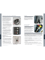
Optional Shower System – Operating Procedure
Filling Water Tank
The water filler is found under the forward
seat cushion of the boat and is connected to
a 20 litre tank. It is impossible to completely
evacuate the system of water; therefore the
following procedure should be followed to best
prevent the development of micro-organisms.
Before First Use
Partly fill the tank with warm water (50°c) and •
a 1% solution of mild detergent.
After a few minutes, rinse with clear water •
and fill it again with water treated with
chlorine tablets (follow package instructions
for a 5% concentration).
Empty after 2 hours and carefully and •
thoroughly rinse with clear water.
When in Use
Each time the tank is filled, add chlorine •
tablets at the dosage specified by the
supplier.
Every 6 months repeat the procedure stated •
for Before First Use.
Before Extended Storage
Keep tank partly filled with water and 10% of •
chlorine solution.
Before using the tank again follow the •
procedure stated for Before First Use.
Using Shower
Check the boat isolator and shower isolator •
switches are in their ON positions.
Fit shower head/pipe connector into shower •
attachment and twist clockwise to start water
flow.
When finished turn head counter-clockwise •
to stop water flow (always return head to
closed position, even when there is no water
flow).
Return shower isolator to • OFF position.
3 Shower attachment
3
1 Water filler
1
2 Shower isolator
2
Reverse System
The forward and reverse operation is powered
by an electric actuator located within the
engine tray. This item requires no servicing,
but cables should be inspected and greased
according to the periodic maintenance table.
Shaft Seal Lubrication
Shaft seal lubrication is provided by an
automatic grease unit. Inspect reservoir level
approximately every 10 hours of operation. Use
a premium, multipurpose calcium sulphonate
grease or equivalent high temperature, high
speed bearing grease to re-fill reservoir. Take
care not to over-pressurise system. DO NOT
exceed maximum level indication.
Routine Maintenance
To ensure long service life and to maintain the tender in a safe and reliable condition
please follow these routine maintenance instructions. Williams cannot accept any
responsibility for damage or injury resulting from incorrect maintenance or improper
adjustment carried out by the owner.
1 Wash tender regularly with fresh water to remove salt deposits.
2 Inspect automatic grease unit reservoir and refill as required.
3 Check engine oil level (refer to section Oil Level Check in this handbook).
4 Check coolant level.
5 Flush open loop cooling system.
6 Apply a good quality marine grease containing Teflon (e.g. Quicksilver 101) to all control
cables both under the helm and at the pump.
7 Check bilges for water ingress, oil or fuel contamination and clean if necessary.
8 Lightly grease the extending running light pole using white grease or similar.
9 Check condition of anodes around pump area.
10 Loss of tube pressure over 24 hours is not unusual. Temperature and atmospheric pressure
will affect tube pressures. Check pressures regularly.
Max

English
20
www.williamsjettenders.com
English
21
www.williamsjettenders.com
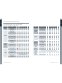
Full Inspection Maintenance Table
•
Check or clean
•
Replace
•
Contact your authorised Williams Dealer
•
Refer to Yanmar Engine Manual
•
Refer to Yanmar Service Manual
•
Initial 50 hours only
•
During use
•
After starting
System Item
Every
use
Regular intervals (hours)
50 250 500 1000
End of
year
Engine
•
Visual inspection of
engine exterior
•
Fuel system
Check fuel level.
Refill if necessary
• •
Drain water and sediment
from fuel tank
• • •
Drain fuel/water separator
•
Replace fuel filter element
• •
Check fuel injection timing
•
Check fuel injector
spray pattern
•
Lubricating
system
•
Check lube oil level
•
Replace lube oil
• •
Replace oil filter element
• • •
Cooling
system
Seawater filter
• •
Check coolant level
•
Check or replace seawater
pump impeller
•
• •
Replace coolant
•
Every year (2 years if Long Life), see Yanmar
operation manual specifications
Clean and check
seawater passages
•
System Item
Every
use
Regular intervals (hours)
50 250 500 1000
End of
year
Air intake
& exhaust
system
Clean intake silencer
(air cleaner) element
•
Clean or replace the
exhaust/water mixing elbow
• • •
Clean the turbocharger
•
•
Electrical
system
Check alarms and gauges
•
Adjust or replace
alternator V-belt
• • •
Check electrical connectors
•
Engine
cylinder head
& block
Check for leakages of fuel,
engine oil and coolant
•
Tighten all major
nuts and bolts
•
Adjust intake/exhaust
valve clearance
•
Control
cables
Check operation
• • • •
Reverse
system
Check and adjust
• • •
Hoses
(fuel & water)
Replace every 2 years or 2000 hrs, whichever comes first
Pump
anodes
• •
Shaft seal
reservoir
Check every 10 hours
• •

English
22
www.williamsjettenders.com
English
23
www.williamsjettenders.com
Servicing
The important post run-in 1st service is required at 50 hours. Thereafter servicing is
required according to Maintenance Table or yearly, whichever comes first. Consult your
Williams authorized dealer for servicing. Refer to the Yanmar service manual for periodic
engine maintenance.
For parts and accessories please contact your Williams authorized dealer.
Winterising/Dry Storage
Store the boat covered, in a clean, ventilated and dry place that is not affected by major
variations in temperature or humidity. This is a general best practice guide. For full
information on engine maintenance please refer to the YANMAR engine service manual.
Buoyancy Tube
Prior to storing over the winter periods the buoyancy tubes must be deflated and hosed down
with fresh water, removing any small stones and weed from luffing track, then allowed dry. Use
a proprietary tube cleaner and polish to ensure optimum condition. Store with the tubes lightly
inflated where possible.
Maintenance of the Hull & Deck
Wash the deck regularly using a mild detergent in warm water and hose down to remove sand
etc. The hull and deck should be regularly polished using a good quality gelcoat polish to
minimise fade and UV chalking.
Battery
The battery used in the Dieseljet is of the dry cell type and as such if replacing the battery
ensure an AGM type is used. This means that the electrolyte content is absorbed in a special
fabric which requires no ‘topping up’ and is leak proof in any position. When the boat is not
being used for an extended period of time, disconnect the earth terminal. A trickle-charging
device, such as an ‘Accumate’, will extend battery life.
Fuel System
A full fuel tank prevents moisture and mildew from developing within the tank. Drain water from
fuel separator.
Cooling System
Flush the open loop water circuit to remove salt, sand, shells and other contaminants that
may be trapped in the raw water cooling circuit (refer to Flushing Procedure section). Remove
engine raw water impeller if not in use for long periods. Measure the anti-freeze content of
the engine coolant with a commercially available anti-freeze tester. A 50/50 mixture of distilled
water to propylene glycol provides sufficient frost protection to approx. -37°C, drain raw water
from engine OR run the same 50/50 antifreeze mixture through the open loop system via
the raw water strainer and with the isolator valve in the OFF position. See engine manual for
location of engine drain cocks.
Control Cables
Grease all control cables at both ends and exercise in and out to ensure good coverage.
General Corrosion Protection
Apply ‘Vaseline’ or similar white grease to battery isolator switch, upholstery press studs and
telescopic running light. Use maintenance spray on key switch. Apply a proprietary corrosion
guard to engine, electrical connections, under seat, under helm and around jet pump area.
Limited Warranty
Williams Performance Tenders Ltd. 2012 Model Year Limited Warranty Certificate
Williams Performance Tenders (“Williams”) undertake a PDI (pre-delivery inspection) on all new boats before shipment
from factory. Williams will provide for repairs to their inflatable boats during the specific warranty periods provided herein,
in accordance with the following terms, conditions and limitations. Registration of Williams boat – Each Williams boat is
supplied to the original customer with a registration card. The limited Warranty contained herein shall not take effect and
shall be deemed null and void unless the original owner submits a completed registration card to Williams Performance
Tenders Ltd, Unit 2 Vogue Business Park, Berinsfield, Oxon OX10 7LN. UK within 30 days from the date of original
registration. Williams approved dealers shall be entitled to store boats for a period of up to 6 months prior to registration
provided that: a) The boats are stored in original packaging in accordance with Williams guidelines; b) Registration is
recorded upon handover with delivery hours only.
Warranty coverage:
Williams warrants to the original private purchaser of a properly registered craft that: a) All seams of the tubes, inflation
valves, and the fabric used in the construction of the tube shall be free from defects in material and workmanship for a
period of 3 years from the date of the original registration; b) The fabric of the tube shall be free from deterioration affecting
serviceability (i.e. cracking, porosity, but not discolouration, fading or chaffing) for a period of 3 years from the date of the
original registration; c) the fibreglass hull shall be free from defects in material and workmanship for a period of 2 years from
the date of the original registration; d) all components fitted to the boat at the Williams factory or subsequently replaced
under warranty shall be free from defects in material and workmanship for a period of 2 years from the date of the original
registration. The warranty period for commercial use owners will be 4 months from the date of original registration. The
obligation of Williams under this Limited Warranty is limited to repairing or replacing, as Williams may elect at its sole
discretion, any parts that prove, in Williams’ sole judgement, to be defective in material or workmanship. THIS LIMITED
WARRANTY SHALL BE THE ORIGINAL PURCHASER’S SOLE AND EXCLUSIVE REMEDY.
What is not covered:
This Limited Warranty shall not apply to: a) normal wear and tear; b) any minor boat damage, including but not limited to,
gel coat crazing, fading or blistering; c) Any damage to Williams boats due to negligence, accident, misuse, alteration,
improper operation, collision, fire, theft, vandalism, riot, explosion, objects striking the boat, improper maintenance and
storage; d) Any damage caused by towing a Williams boat, any damage caused by lifting or recovering a Williams boat;
e) Tubes exposed to harsh or corrosive chemicals; f) any parts installed by anyone other than Williams factory personnel;
g) any damage caused by after-market parts; h) Williams boats purchased for commercial/governmental use; i) any work
carried out on a Williams boat by an unauthorised service centre and/or without Williams’ prior approval; j) labour, freight,
delivery, storage or other similar charges; k) defects caused or worsened by failure to adhere to the instructions concerning
the treatment, maintenance and care of the boat; l) Damage caused by water ingestion. Sometimes equipment installed
on a Williams boat (such as electronics) carry their own individual warranties provided by their respective manufacturers. In
such cases any warranty claims regarding those parts must be directed to those manufacturers and not Williams. Williams
reserves the right to make warranty coverage contingent upon proof of proper maintenance.
How to obtain Warranty repair:
Prior to any work being commenced on a Williams boat, the warranty claim must be approved in writing by Williams
Performance Tenders Ltd. In order to obtain warranty repair approval, the original owner must send written notification,
along with a copy of the bill of sale, and photograph depicting the damage and/or defect sought to be repaired to Williams
Performance Tenders Ltd, Unit 2 Vogue Business Park, Berinsfield, Oxon OX10 7LN. U.K. If Williams finds that the specific
defect and/or damage is covered under this Limited Warranty, Williams will advise the owner in writing where to send (via
pre-paid freight) the boat or part(s) for repair or replacement. In many cases the local authorised Sales and Service Centre
may be utilised for repairs. In others the boat or parts must be repaired by Williams personnel only. Williams does not
assume any liability for any work performed on a Williams boat at an unauthorised Service Centre and/or without Williams’
prior approval. All parts replaced under this Limited warranty become the property of Williams.
Miscellaneous:
Williams does not authorise any person to create for it any other obligation or liability in connection with its boats. THIS
LIMITED WARRANTY AND WILLIAMS’ OBLIGATION HEREUNDER IS IN LIEU OF ALL WARRANTIES EXPRESS OR
IMPLIED, INCLUDING WITHOUT LIMITATION THE WARRANTIES OF MERCHANTABILITY AND FITNESS FOR A
PARTICULAR PURPOSE. Williams will not be liable for any incidental or consequential damages resulting from breach
of this limited warranty, including without limitation, loss of inflatable boat use, storage, payment for loss of time,
inconvenience, boat rental expense, and local taxes required on warranty repairs. Williams reserves the right to alter
models, change colors, specifications, materials, equipment, component parts, prices or cease production of certain
models at any time without prior notice, and such changes, alterations, or cessation shall be made without Williams
incurring any obligations to equip or modify inflatable boats produced prior to the date of such changes or alterations. This
Limited Warranty shall be governed by and construed and enforced in accordance with UK Law.

www.williamsjettenders.com
Français
25
www.williamsjettenders.com
Français
24
Félicitations Pour Avoir Choisi un
Williams Dieseljet
Ce manuel du propriétaire a été élaboré afin de vous aider à utiliser votre Dieseljet en toute
sécurité. Il contient un descriptif détaillé du bateau et de ses équipements ainsi que des
informations sur son fonctionnement et son entretien. Prenez le temps de le lire attentivement
pour vous familiariser avec votre nouveau bateau avant de l’utiliser.
Le WILLIAMS Dieseljet utilise un mode de propulsion à jet d’eau. S’il s’agit de votre premier
bateau ou que vous changiez pour un bateau qui ne vous est pas familié, assurez- vous, pour
votre propre sécurité, d’acquérir les compétences nécessaires à son fonctionnement et à son
pilotage avant d’en assumer le commandement. Votre concessionnaire ou l’importateur seront
heureux de vous diriger vers une école de navigation ou un instructeur compétent.
Pour pouvoir profiter de la garantie du moteur Yanmar, n’oubliez pas d’enregistrer votre moteur
en ligne sur le site www.yanmarmarine.com.
Le 505D Dieseljet est un bateau très performant. Williams recommande qu’une
qualification au minimum , telle que RYA niveau 2, permis A ou Mer, ou Certificat
International de Compétence, soit acquise par l’utilisateur avant d’en prendre le contrôle.
Ce manuel considère que l’utilisateur possède ce niveau de qualification ainsi que les
connaissances de base du marin.
Merci de conserver ce manuel en lieu sur et de le donner au nouveau
propriétaire à la vente du bateau.
Numéro d’Identification de la Coque (HIN):
Sécurité
La sécurité est très importante pour Williams Performance Tenders et cette société
recommande que toutes les personnes qui entrent en contact avec ses embarcations et
ses autres produits, comme les responsables de l’entretien ou des réparations des produits
Williams, fassent attention, fassent preuve de bon sens et observent les informations
relatives à la sécurité figurant dans ce manuel et sur les étiquettes de sécurité affichées sur
les embarcations. Conservez les étiquettes en bon état et remplacez-les si elles deviennent
illisibles. En outre, si vous devez remplacer une pièce comportant une étiquette, veuillez vous
assurer de commander l’étiquette fixée à cette pièce, en commandant la pièce et l’étiquette en
même temps.
Soyez au courant des lois locales et des restrictions et ne jamais utiliser sous l’influence de
l’alcool ou toute autre substance qui peut affecter votre jugement.
Ce symbole apparaît sur un nombre d’étiquettes fixées à l’embarcation.
Ce symbole devrait attirer votre attention sur le message et vous référer au manuel
d’utilisation.
Ce symbole d’alerte de sécurité apparaît tout au long de ce manuel d’utilisation et
apparaît sur différentes étiquettes fixées à l’embarcation. Il signifie: attention, soyez
vigilent(e), votre sécurité est concernée! Veuillez lire et respecter le message qui suit le
symbole d’alerte de sécurité.
DANGER Indique une situation dangereuse qui, si elle n’est pas évitée, entraînera la mort ou
des blessures graves.
AVERTISSEMENT Indique une situation dangereuse qui, si elle n’est pas évitée, pourrait
entraîner la mort ou des blessures graves.
ATTENTION Indique une situation dangereuse qui, si elle n’est pas évitée, pourrait entraîner
des blessures légères ou de gravité modérée.
Caracteristiques Moteur
Dieseljet 445 & 505 Dieseljet 565 Dieseljet 625
Yanmar Moteur
4JH4-HTE 110 HP 4BY2 150 HP 4BY2 180 HP
Puissance
maximum
(vilebrequin)
80.9 kW (110 cv) /
3200 tr/min
110 kW (150 cv) /
4000 tr/min
132 kW (180 cv) /
4000 tr/min
Configuration
Diesel à injection directe, turbo-compressé, refroidissement liquide
Cylindrée
1.995 L (122 cu in)
No. de cylindres
4, 4-soupapes par cylindre
Refroidissement
Eau douce par pompe à eau centrifuge et
eau de mer par turbine en caoutchouc
Catégorie de Conception
Catégorie C – « à proximité des côtes » : navire de plaisance conçus pour la navigation à
proximité des côtes, dans de grandes baies, des estuaires, des lacs et des rivières, durant
laquelle les vents peuvent aller jusqu’à la force 6 comprise et les vagues peuvent atteindre une
hauteur significative jusqu’à 2m compris. Ce bateau est conforme à la norme ISO 6185-3. Le
numéro d’identification de la coque se trouve au dessus de la turbine et sous la plateforme
arrière. Notez- le dans le cadre ci-dessus. La plaque CE se trouve sur le franc bord arrière
tribord. La plaque CE certifie la conformité à la Directive Européenne 94/25/CE.
Huile
Viscosité 15W40 Viscosité 0W40 – 10W30
Normes API CD ou supérieures
Liquide de
refroidissement
Texaco Long Life
Coolant (LLC)
ou liquide antigel
longue durée
30%-60% type
Havoline
Liquide de refroidissement
Glysantin G48-24
Carburant
Diesel

www.williamsjettenders.com
27
www.williamsjettenders.com
Français
26
Français
Dieseljet 505 – Aménagement Général
1 Prise pour feux de navigation bâbord/tribord
2 Puits de chaine (sous le coussin)
3 Bouchon de remplissage et pomme
4 Coffre de rangement
5 Poignées passagers de maintien
6 Bouchons de nables
7 Embases de poignée d’embarquement
8 Remplissage carburant
9 Boitier de commande
accélération/inversion
10 Valves de gonflage
11 Coupe batterie principal
12 Valves de surpression
13 Prise auxiliaire 12v alimentation/charge
14 Prise pour feu blanc 360°
15 Taquet d’amarrage (bâbord et tribord)
16 Anneau de traction ski nautique
17 Numéro d’identification de coque (HIN)
(sous la plateforme)
18 Raccord de rinçage moteur
@
indique les places assises
General specifications
Longueur
5.05 m
Largeur
2.02 m
Hauteur
1.1 m
Tirant d’eau
0.27 – 0.42 m
Poids à vide
820 kg
Personnes
8
Carburant
85 litres
Vitesse
maximum
34 knots
Dieseljet 445 – Aménagement Général
1 Prise pour feux de navigation bâbord/tribord
2 Puits de chaine (sous le coussin)
3 Bouchon de remplissage et pomme
4 Coffre de rangement
5 Poignées passagers de maintien
6 Bouchons de nables
7 Embases de poignée d’embarquement
8 Remplissage carburant
9 Boitier de commande
accélération/inversion
10 Valves de gonflage
11 Coupe batterie principal
12 Valves de surpression
13 Prise auxiliaire 12v alimentation/charge
14 Prise pour feu blanc 360°
15 Taquet d’amarrage (bâbord et tribord)
16 Anneau de traction ski nautique
17 Numéro d’identification de coque (HIN)
(sous la plateforme)
18 Raccord de rinçage moteur
@
indique les places assises
Characteristiqes générales
Longueur
4.45 m
Largeur
2.02 m
Hauteur
1.1 m
Tirant d’eau
0.27 – 0.42 m
Poids à vide
755 kg
Personnes
7
Carburant
50 litres
Vitesse
maximum
35 knots
4
4
4
4
4
5
5
5
5
6
6
6
6
6
6
6
6
1
1
7
7
7
7
9
9
10
10
10
10
10
10
10
12
12
12
8
8
14
14
12
12
11
17
17
16
16
2 2
3
3
3
5
13
13
134 11
@
@
@
@
@
@
@
@
@
@
@
@
@
@ @
15
15
15
15
18
18
3

28
www.williamsjettenders.com
Français
29
www.williamsjettenders.com
Français
Dieseljet 565 – Aménagement Général
1 Prise pour feux de navigation bâbord/tribord
2 Puits de chaine (sous le coussin)
3 Bouchon de remplissage et pomme
4 Coffre de rangement
5 Poignées passagers de maintien
6 Bouchons de nables
7 Embases de poignée d’embarquement
8 Remplissage carburant
9 Boitier de commande
accélération/inversion
10 Valves de gonflage
11 Coupe batterie principal
12 Valves de surpression
13 Prise auxiliaire 12v alimentation/charge
14 Prise pour feu blanc 360°
15 Taquet d’amarrage (bâbord et tribord)
16 Anneau de traction ski nautique
17 Numéro d’identification de coque (HIN)
(sous la plateforme)
18 Raccord de rinçage moteur
@
indique les places assises
Characteristiqes générales
Longueur
5.65 m
Largeur
2.35 m
Hauteur
1.16 m
Tirant d’eau
0.35 – 0.5 m
Poids à vide
1060 kg
Personnes
9
Carburant
105 litres
Vitesse
maximum
36 knots
Dieseljet 625 – Aménagement Général
1 Prise pour feux de navigation bâbord/tribord
2 Puits de chaine (sous le coussin)
3 Bouchon de remplissage et pomme
4 Coffre de rangement
5 Poignées passagers de maintien
6 Bouchons de nables
7 Embases de poignée d’embarquement
8 Remplissage carburant
9 Boitier de commande
accélération/inversion
10 Valves de gonflage
11 Coupe batterie principal
12 Valves de surpression
13 Prise auxiliaire 12v
alimentation/charge
14 Prise pour feu blanc 360°
15 Taquet d’amarrage (bâbord et tribord)
16 Anneau de traction ski nautique
17 Numéro d’identification de coque
(HIN) (sous la plateforme)
18 Raccord de rinçage moteur
@
indique les places assises
Characteristiqes générales
Longueur
6.25 m
Largeur
2.35 m
Hauteur
1.16 m
Tirant d’eau
0.35 – 0.5 m
Poids à vide
1250 kg
Personnes
11
Carburant
120 litres
Vitesse
maximum
36 knots
4 4
4
5
5
5
5
6
6
6
6
6
6
6
6
1 1
7
7
7
7
9
9
10 10
10 10
10
10 10
10
12 12
12
12
12
8
8
14
14
12
114
114
17
17
16
16
2
2
3
3
3
3
18
13
13
@
@
@
@
@
@ @
@@
@
@
@
@
@
@
@
@ @
15
15
15
15
4
4 4
@ @
18
5
5

www.williamsjettenders.com
31
www.williamsjettenders.com
Français
30
Français
Utilisation de Votre Annexe
Ce bateau utilise un système de propulsion à jet d’eau qui lui confère des caractéristiques de
maniabilité exceptionnelles. L’accélération produit une poussée par la turbine, le contrôle
directionnel se fait en accélérant et en tournant le volant dans la direction voulue. Une forte
poussée fera tourner le bateau brusquement; une faible poussée produira moins de force en
virage. Il n’y a pas de gouvernail, il faut obligatoirement de la poussée pour avoir de la maniabilité.
ATTENTION: La maniabilité est sévèrement restreint avec accélérateur réduit oupendant
la décélération.
Après avoir utilisé l’annexe à haute vitesse, il est important de laisser tourner le moteur au ralenti
pendant au moins 1 minute avant l’arrêt afin de laisser refroidir le turbo.
Si des algues, un sac plastique ou des débris se prennent dans la turbine pendant l’utilisation,
un phénomène de cavitation peut survenir, causant une perte de poussée. S’il y a des signes de
débris, d’algues, etc, obstruant la turbine, sortir le bateau de l’eau. Coupez la batterie et enlevez
tous les débris de la turbine. NE PAS faire de tentatives répétées de démarrage d’une annexe
bloquée ou forçant, cela peut gravement l’endommager. En cas de difficulté, contactez votre
concessionnaire officiel Williams.
Récuperation
AVERTISSEMENT: ne pas essayer de lever ou
récupérer l’annexe par le tableau arrière. En la relevant
par l’arrière, cela provoquerait une entrée d’eau dans le moteur
par le système d’échappement et l’endommagerait gravement.
Utilisation Forcée du Système d’Inversion
Dans le cas d’une défaillance du servomoteur d’inversion, il
est possible de mettre l’annexe en marche avant de manière
forcée. Il faut retirer la goupille à blocage située en bout de
câble pour le libérer et le fixer avec cette goupille dans le
support situé en avant, voir la photo.
Mouillage
AVERTISSEMENT: Ne laissez pas votre Turbojet au
mouillage ou au port pour de longues périodes afin
d’éviter l’apparition d’algues et coquillages qui diminueraient
les performances.
Accoster sur la Plage
AVERTISSEMENT: NE PAS manœuvrer dans moins de
0.50m d’eau car du sable, des graviers ou des algues pourraient entrer dans la turbine.
NE PAS accoster sur la plage avec le moteur en marche. Coupez le moteur avant d’accoster car
cela pourrait endommager la turbine et boucher le circuit de refroidissement moteur.
En repartant, poussez le bateau en eau plus profonde et balancez le d’un coté à l’autre plusieurs
fois avant de le démarrer pour enlever le sable de la turbine – ne pas le faire peut endommager
la turbine.
Equilibrage
AVERTISSEMENT: ne pas surcharger le bateau plus qu’indiqué sur la plaque. A toutes les
vitesses, soyez conscient de l’assiette du bateau et répartissez les poids en conséquence.
Généralités
Adaptez une conduite responsable et une vitesse appropriée à l’état de la mer. Renseignez vous
sur la législation et les restrictions locales. Faites toujours un contrôle visuel du bateau et de
ses équipements avant de l’utiliser. Respectez le programme de révision détaillé dans le manuel
d’entretien.
Enlevez la goupillede
sécurité, tirez manuelle-
ment le câble en avant,
et fixez le câble avec la
goupille dans le support
situé devant, sur la cloison.
Tableau d’Instruments de Contrôle
Dieseljet 445 & 505
1 compte tours
2 compteur de vitesse
3 indicateur de
température d’eau
4 indicateur de pression
d’huile
5 jauge carburant
6 tableau de voyants
d’alarme
7 radio VHF
8 cordon coupe circuit de
sécurité
9 interrupteur de feux de
navigation
10 interrupteur de ventilateur
de cale
11 interrupteur de pompe de
cale en marche forcée
12 interrupteur de klaxon
13 interrupteur de feux de
pont
14 interrupteur de douche
15 commande des gaz
16 traceur de cartes
17 couton d’arrêt du
moteur
18 clé de contact
Dieseljet 565 & 625
1 compte tours
2 compteur de vitesse
3 indicateur de pression
d’huile
4 jauge carburant
5 indicateur de
température d’eau
6 voltmètre
7 Système musical
8 radio VHF
9 cordon coupe circuit de
sécurité
10 interrupteur de feux de
navigation
11 interrupteur de
ventilateur de cale
12 interrupteur de pompe de
cale en marche forcée
13 interrupteur de klaxon
14 interrupteur de feux de
pont
15 interrupteur de douche
16 commande des gaz
17 traceur de cartes
18 voyant
d’avertissement
de pression
d’huile
19 clé de
contact
15
16
13
14
18
12
11
17
10
9
8
7
3
1
4
2
65
73
1
4
2
6
5
9
8
13
15
16
19
14
12
18
11
10
17

32
www.williamsjettenders.com
Français
33
www.williamsjettenders.com
Français
Période de Rôdage Moteur
La manière dont va être utilisé votre moteur durant les 50 premières heures de fonctionnement
sera déterminante pour ses performances maximum et sa durée de vie. Le moteur doit être
utilisé aux vitesses et réglages de puissance adaptés durant la période de rodage. La page
14 du manuel d’utilisation du Yanmar série JH4 contient des informations essentielles sur
l’utilisation du moteur durant les 50 premières heures d’utilisation.
Remplissage Carburant
Dans le cadre du contrôle avant livraison, votre nouveau Turbojet a été intégralement
testé et, éventuellement, vidangé de son carburant. Lorsque vous faites le plein, utilisez
uniquement du carburant DIESEL.
Ne pas faire le plein avec le moteur en marche.•
Enlevez le coussin d’assise console pour atteindre le bouchon de remplissage.•
Faites le plein dans un endroit ventilé.•
Ne pas faire déborder le réservoir; ne pas renverser de carburant.•
Serrez correctement le bouchon de remplissage après avoir fait le plein.•
Ouvrez le compartiment moteur et vérifiez le fond de cale après avoir fait le plein.•
Le bouchon de remplissage est équipé d’une mise à l’air intégrale.•
NE PAS laver au jet d’eau autour du bouchon de remplissage car l’eau pourrait rentrer dans •
le réservoir.
Remarque : si le moteur est équipé d’un amorceur/d’une pompe de carburant, un
pompage peut être requis lors de la première utilisation ou après une longue période
d’inutilisation.
Avant Utilisation
La pression du tubulaire varie en fonction de la température de l’air. Gonflez les compartiments
du tubulaire à 250mB/3.6psi en suivant l’ordre indiqué sur les valves, commencez par l’arrière.
Ne pas respecter cette procédure compromettra la tenue en mer et l’étanchéité totale du
bateau. Les valves de gonflage ont des clapets quart de tour permettant un dégonflage rapide.
Vérifiez que les clapets de valves sont fermés et gonflez les compartiments de manière •
égale en commençant par l’arrière droit, l’arrière gauche puis les valves d’avant.
Contrôlez qu’il n’y ait pas d’eau ou d’essence dans le fond de cale.•
Vérifiez que les loquets de capot moteur sont bloqués.•
Vérification de Sécurité!
ATTENTION: TOUJOURS vous attacher avec le cordon de sécurité quand le moteur est
en marche. Avant de partir et à titre de précaution, toujours tester le cordon de sécurité
en tirant dessus pour le déconnecter du coupe circuit – le moteur doit toujours s’arrêter.
ATTENTION: NE JAMAIS manœuvrer le bateau lorsque des baigneurs utilisent l’échelle
de bain, le déflecteur de marche arrière pouvant entrainer des blessures graves.
ATTENTION: NE JAMAIS examiner le compartiment moteur quand le moteur tourne ou
avec le contact.
Démarrer Votre Dieseljet
NE JAMAIS démarrer le moteur si la température est excessivement élevée ou en •
dessous de -16°C (-5°F).
NE JAMAIS essayer d’arrêter le moteur en utilisant le coupe batterie.•
Assurez-vous que la profondeur d’eau sous le bateau soit au moins de 0.50m.•
Assurez-vous que tous les passagers sont assis correctement.•
1 Tournez le coupe batterie sur la position « ON ».
2 Ventilez la cale moteur pendant 4 minutes.
3 Vérifiez qu’il n’y ait pas de cordes détachées qui pourraient être aspirées par la turbine.
4 Vérifiez que le levier de commande est au point mort.
5 AVERTISSEMENT: Connectez le cordon de sécurité au coupe circuit et vérifiez
qu’il fonctionne bien – voir ci-dessus Vérification de Sécurité.
6 Tournez la clef de contact jusqu’au démarrage du moteur, utiliser la fonction préchauffage
par temps froid si nécessaire.
7 Testez la longe de sécurité pour vérifier son bon fonctionnement (consultez Vérification de
sécurité ! à la page 28).
Voyants d’Alarme/Alarme
ATTENTION: Risque d’endommagement du moteur. Dans le cas où un voyant
d’avertissement ou un avertisseur sonore s’active pendant l’utilisation, ARRÊTER
immédiatement le moteur, rechercher la cause et consulter le manuel du moteur. Contacter
votre revendeur Williams agréé.
Après Utilisation
Afin de prolonger sa durée de vie, il est très important de laver entièrement le bateau
à l’eau douce après utilisation et avant stockage, plus particulièrement la turbine.
Le manque de rinçage régulier réduira de manière significative la durée de vie des
composants situés dans l’eau. Vérifiez les anodes régulièrement.
Lavez la turbine.•
Contrôlez le fond de cale et séchez toute eau résiduelle.•
Rincez les planchers à l’eau douce.•
Coupez la batterie.•
1 Anodes de turbine 2 Anode de coque 3 Anode d’auget d’inversion
1
3
1
2

34
www.williamsjettenders.com
Français
35
www.williamsjettenders.com
Français
Procédure de Rincage
Afin de prolonger la vie du moteur, il est très important de rincer le moteur à l’eau douce
pour évacuer le sel après utilisation et avant stockage. Le manque de rinçage régulier
réduira de manière significative la durée de vie de certains composants du moteur et peut
invalider la garantie. NE PAS accélérer hors de l’eau. De plus, il est conseillé de rincer
consciencieusement à l’eau douce la turbine et autour d’elle, pour enlever toute trace de sel
après utilisation.
ATTENTION: le moteur DOIT être en marche
avant de brancher l’eau. Il y a un risque de
noyer le moteur si l’eau continue d’arriver après que
le moteur soit arrêté.
1 Brancher un tuyau d’eau douce équipé du
raccord mâle fourni avec l’annexe au raccord
femelle fixé sur le bateau (1).
2 Démarrer le moteur et ouvrir l’eau
immédiatement.
3 Faire tourner le moteur au ralenti pendant 1
minute environ afin de rincer complètement le
circuit de refroidissement ouvert.
4 Couper l’eau.
5 Laissez tourner le moteur pendant 10 secondes
au maximum pour évacuer l’eau du système
de refroidissement, puis arrêter le moteur.
Débranchez le tuyau d’eau du raccord de
rinçage.
6 Vérifiez le fond de cale du bateau et séchez
toute eau résiduelle. Enlevez les bouchons de
nable.
Vérification du Niveau d’Huile
Le moteur doit être à température de fonctionnement pour que le niveau exact soit
indiqué sur la jauge.
Le niveau d’huile doit être entre MIN et MAX sur la jauge.•
Ne pas visser le bouchon pour vérifier le niveau.•
Utiliser la viscosité d’huile préconisée.•
Ne pas remplir au-dessus de MAX.•
ATTENTION: l’utilisation d’une huile moteur autre que celle préconisée peut engendrer
le grippage de pièces internes ou une usure précoce, ayant pour résultat de réduire la
durée de vie du moteur.
Panneau Electrique
Le panneau électrique de commande de l’embarcation est situé sous la console de pilotage. Il
comprend un certain nombre de composants électriques, dont :
les disjoncteurs des composants, le sectionneur de batterie, le disjoncteur thermique et une
prise de courant de 12 V.
AVERTISSEMENT: LE FAIT D’UTILISER LE SECTIONNEUR POUR ARRÊTER LE
MOTEUR ENTRAÎNERA L’ENDOMMAGEMENT DU CIRCUIT DE CHARGE ET LA
PERTE DE L’ACTIONNEUR INVERSE ET DE LA LONGE DE SÉCURITÉ.
Tableau des Codes Couleur des Câbles
Le tableau ci-dessous présente la couleur correspondant à toutes les abréviations imprimées
des câbles. Veuillez également consulter le CD de ressources techniques de Williams pour le
schéma du circuit électrique.
Abréviation Couleur Abréviation Couleur
BK Noir VT Violet
GN Vert RD Rouge
PK Rose GY Gris
LTGN Vert clair BE Bleu
BN Marron WE Blanc
OE Orange YW Jaune
Exemple : GN/YW signifiera Vert/Jaune
1 Raccord de rincage
1

36
www.williamsjettenders.com
Français
37
www.williamsjettenders.com
Français
Compartiment Moteur
Dieseljet 445 & 505
Dieseljet 565 & 625
3
1
4
6
8
10
2
5
7
9
14
1
6
8
10
13
12
2
5
7
9
1 Bouchon pressurisé de liquide de refroidissement
2 Remplissage huile
3 Pompe d’amorçage carburant/filtre secondaire
4 Filtre séparateur eau/gasoil
5 Cadran de contrôle de l’extincteur
6 Vase d’expansion de liquide de refroidissement
7 Filtre eau de mer
8 Graisseur automatique
9 Servomoteur de commande d’inversion
10 Ventilateur de cale
11 Pompe de vidange des planchers et puisard
12 Jauge d’huile de moteur
13 Alternateur
1 Bouchon pressurisé de liquide de refroidissement
2 Remplissage huile
3 Filtre d’huile
4 Alternateur
5 Cadran de contrôle de l’extincteur
6 Extincteur
7 Filtre séparateur eau/gasoil
8 Servomoteur de commande d’inversion
9 Filtre eau de mer
10 Graisseur automatique
11 Pompe de vidange des planchers et puisard
12 Vase d’expansion de liquide de refroidissement
13 Filtre à air
14 Jauge d’huile de moteur
12
11
11
3
4
13

38
www.williamsjettenders.com
Français
39
www.williamsjettenders.com
Français
Douche Optionnelle – Fonctionnement
Remplissage du Réservoir d’Eau
L’orifice de remplissage d’eau se trouve sur
le franc bord bâbord du bateau et est relié
à un réservoir de 20 litres. Il est impossible
d’évacuer l’eau en intégralité du système ; en
conséquence, il faudra suivre la procédure
ci-dessous pour prévenir au mieux le
développement de micro organismes.
Avant la Première Utilisation
Remplir en partie le réservoir d’eau chaude •
(50°C) et une solution à 1% d’un détergent
doux.
Après quelques minutes, rincer à l’eau douce •
et remplir le réservoir d’eau traité avec des
tablettes de chlore (suivre les instructions sur
l’emballage pour une concentration à 5%).
Vider après 2 heures et rincer à l’eau claire •
avec précaution et consciencieusement.
A l’Utilisation
A chaque remplissage du réservoir, ajouter •
des tablettes de chlore au dosage spécifié par
le fournisseur.
Tous les 6 mois, répéter l’opération « • Avant la
première utilisation ».
Avant une Longue Période
de Stockage
Garder le réservoir en partie rempli avec de •
l’eau et 10% de chlore.
Avant de réutiliser le réservoir, suivre la •
procédure « Avant la première utilisation ».
Utilisation de la Douche
Contrôler que le coupe batterie et l’interrupteur •
de douche soient en position « ON ».
Tirer la douchette de son logement et tourner •
la tête dans le sens des aiguilles d’une montre
pour faire couler l’eau.
Pour arrêter l’eau de couler, tourner la tête •
de la douchette dans le sens contraire des
aiguilles d’une montre (toujours tourner la tête
en position fermée, même quand il n’y a pas
d’eau qui coule).
Remettre avec précaution le tuyau dans son •
logement et vérifier que la douchette est bien
en place.
Remettre l’interrupteur de douche sur « • OFF ».
1 Orifice de remplissage
2 Interrupteur de douche
Systeme d’Inversion
La mise en marche avant et arrière est
effectuée par un servomoteur électrique situé
dans le compartiment moteur. Cette pièce
ne nécessite pas d’entretien mais les câbles
devront être contrôlés et graissés selon le
tableau d’entretien périodique.
Graissage du Palier
d’Arbre de Transmission
La lubrification du palier d’étanchéité d’arbre
de transmission est faite par un graisseur
automatique. Vérifiez le niveau de graisse
dans le réservoir toutes les 10 heures de
fonctionnement. Utilisez une graisse au
calcium sulphonate de qualité, multi usage,
ou l’équivalent haute température pour remplir
le réservoir. Faire attention de ne pas sur
pressurisé le circuit.
NE PAS dépasser le niveau maximum indiqué.
Entretien Routinier
Afin d’assurer à votre annexe une longue durée de vie et d’en maintenir la fiabilité et la
sécurité, veuillez suivre ces instructions d’entretien routinier. Williams ne peut être tenu
responsable pout tout dommage ou blessure résultant d’un entretien non suivi ou d’une
intervention mal réalisée par le propriétaire.
1 Lavez entièrement votre bateau à l’eau douce.
2 Vérifiez le niveau du réservoir de graisse du palier et remplissez si nécessaire.
3 Graissez les câbles de contrôle.
4 Vérifiez le niveau d’huile moteur (voir section Verification du Niveau d’Huile).
5 Vérifiez le niveau de liquide de refroidissement.
6 Appliquez une graisse de bonne qualité contenant du Téflon (e.g. Quicksilver 101) sur tous
les câbles de commande, coté boitier et coté turbine.
7 Vérifiez qu’il n’y ait pas d’entrée d’eau, de fuite d’huile ou d’essence dans le fond de cale
et nettoyer si nécessaire.
8 Vérifiez l’usure des anodes de turbine et de plaque.
9 La perte de pression du tubulaire après 24 heures n’est pas anormale. La température et la
pression atmosphérique entrainent une variation de la pression du tubulaire.
10 Vérifiez régulièrement la pression de gonflage.
3 Douchette
3
1
2
Max
La pagina si sta caricando...
La pagina si sta caricando...
La pagina si sta caricando...
La pagina si sta caricando...
La pagina si sta caricando...
La pagina si sta caricando...
La pagina si sta caricando...
La pagina si sta caricando...
La pagina si sta caricando...
La pagina si sta caricando...
La pagina si sta caricando...
La pagina si sta caricando...
La pagina si sta caricando...
La pagina si sta caricando...
La pagina si sta caricando...
La pagina si sta caricando...
La pagina si sta caricando...
La pagina si sta caricando...
La pagina si sta caricando...
La pagina si sta caricando...
La pagina si sta caricando...
La pagina si sta caricando...
La pagina si sta caricando...
La pagina si sta caricando...
La pagina si sta caricando...
La pagina si sta caricando...
La pagina si sta caricando...
La pagina si sta caricando...
La pagina si sta caricando...
La pagina si sta caricando...
La pagina si sta caricando...
La pagina si sta caricando...
La pagina si sta caricando...
La pagina si sta caricando...
La pagina si sta caricando...
La pagina si sta caricando...
La pagina si sta caricando...
La pagina si sta caricando...
La pagina si sta caricando...
La pagina si sta caricando...
La pagina si sta caricando...
La pagina si sta caricando...
La pagina si sta caricando...
-
 1
1
-
 2
2
-
 3
3
-
 4
4
-
 5
5
-
 6
6
-
 7
7
-
 8
8
-
 9
9
-
 10
10
-
 11
11
-
 12
12
-
 13
13
-
 14
14
-
 15
15
-
 16
16
-
 17
17
-
 18
18
-
 19
19
-
 20
20
-
 21
21
-
 22
22
-
 23
23
-
 24
24
-
 25
25
-
 26
26
-
 27
27
-
 28
28
-
 29
29
-
 30
30
-
 31
31
-
 32
32
-
 33
33
-
 34
34
-
 35
35
-
 36
36
-
 37
37
-
 38
38
-
 39
39
-
 40
40
-
 41
41
-
 42
42
-
 43
43
-
 44
44
-
 45
45
-
 46
46
-
 47
47
-
 48
48
-
 49
49
-
 50
50
-
 51
51
-
 52
52
-
 53
53
-
 54
54
-
 55
55
-
 56
56
-
 57
57
-
 58
58
-
 59
59
-
 60
60
-
 61
61
-
 62
62
-
 63
63


Williams DieselJet 505 Owner's Handbook Manual
- Tipo
- Owner's Handbook Manual
- Questo manuale è adatto anche per
in altre lingue
- français: Williams DieselJet 505
- español: Williams DieselJet 505
- Deutsch: Williams DieselJet 505
Documenti correlati
-
Williams DieselJet 505 Owner's Handbook Manual
-
-
-
-
Williams SportJet 460 Owner's Handbook Manual
-
-
-
-
Williams Turbojet 285s Owner's Handbook Manual
Altri documenti
-
Yanmar 6HYM-WET Istruzioni per l'uso
-
Vetus BISEP19 Guida d'installazione
-
Steinbach Solar Shower Manuale del proprietario
-
Bayliner 2017 Generic International Small Craft Manuale utente
-
-
Steinbach 049015 Manuale del proprietario
-
Steinbach 049048 Manuale utente
-
Bossini D46053 Istruzioni per l'uso
-
 New Marine NewCat 16 Special Manuale del proprietario
