La pagina si sta caricando...

REGOLATORE DI PRESSIONE
PRESSURE REGULATOR
DIVAL 160 AP
MANUALE TECNICO MT059
TECHNICAL MANUAL MT059
ISTRUZIONI PER L’INSTALLAZIONE, LA MESSA IN SERVIZIO E LA MANUTENZIONE
INSTALLATION, COMMISSIONING AND MAINTENANCE INSTRUCTIONS
I - E

2
MANUALE TECNICO MT059 TECHNICAL MANUAL MT059
Edizione May 2014 Issue May 2014
DIVAL 160 AP
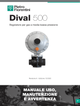
PRESSIONE D’ENTRATA
INLET PRESSURE PRESSIONE D’USCITA
OUTLET PRESSURE

MANUALE TECNICO MT059 TECHNICAL MANUAL MT059
3
AVVERTENZE GENERALI
- L’apparecchiatura descritta in questo manuale è un
dispositivo soggetto a pressione inserito in sistemi
pressurizzati;
- l’apparecchiatura in questione è normalmente inseri-
ta in sistemi che trasportano gas infiammabili (ad
esempio gas naturale).
AVVERTENZE PER GLI OPERATORI
Prima di procedere all’installazione, messa in servizio o
manutenzione gli operatori devono:
- prendere visione delle disposizioni di sicurezza
applicabili all’installazione in cui devono operare;
- ottenere le necessarie autorizzazioni ad operare
quando richieste;
- dotarsi delle necessarie protezioni individuali
(casco, occhiali, ecc.);
- assicurarsi che l’area in cui si deve operare sia dota-
ta delle protezioni collettive previste e delle necessa-
rie indicazioni di sicurezza.
MOVIMENTAZIONE
La movimentazione dell’apparecchiatura e dei suoi
componenti deve essere eseguita dopo aver valutato
che i mezzi di sollevamento siano adeguati ai carichi da
sollevare (capacità di sollevamento e funzionalità). La
movimentazione dell’apparecchiatura deve essere ese-
guita utilizzando i punti di sollevamento previsti sul-
l’apparecchiatura stessa.
L’impiego di mezzi motorizzati è riservato al personale
a ciò preposto.
INSTALLAZIONE
Qualora l’installazione dell’apparecchiatura richieda
l’applicazione in campo di raccordi a compressione,
questi devono essere installati seguendo le istruzioni
del produttore dei raccordi stessi. La scelta del raccor-
do deve essere compatibile con l’impiego specificato
per l’apparecchiatura e con le specifiche di impianto
quando previste.
MESSA IN SERVIZIO
La messa in servizio deve essere eseguita da personale
adeguatamente preparato.
Durante le attività di messa in servizio il personale non
strettamente necessario deve essere allontanato e deve
essere adeguatamente segnalata l’area di interdizione
(cartelli, transenne, ecc.).
Verificare che le tarature dell’apparecchiatura siano
quelle richieste; eventualmente provvedere al loro ripri-
stino ai valori richiesti secondo le modalità indicate
oltre nel manuale.
Durante la messa in servizio devono essere valutati i
rischi determinati da eventuali scarichi in atmosfera di
gas infiammabili o nocivi.
Per installazione su reti di distribuzione per gas natura-
le occorre considerare il rischio di formazioni di misce-
la esplosiva (gas/aria) all’interno delle tubazioni.
GENERAL PRECAUTIONS
- The apparatus described in this manual is a device
subject to pressure installed in systems under pres-
sure;
- the apparatus in question is normally installed in
systems for transporting flammable gases (natural
gas, for example).
PRECAUTIONS FOR THE OPERATORS
Before proceeding with installation, commissioning or
maintenance, operators must:
- examine the safety provisions applicable to the
installation in which they must work;
- obtain the authorisations necessary for working
when so required;
- use the necessary means of individual protection
(helmet, goggles, etc.);
- ensure that the area in which they operate is fitted
with the means of collective protection envisaged
and with the necessary safety indications.
HANDLING
The handling of the apparatus and of its components
must only be carried out after ensuring that the lifting
gear is adequate for the loads to lift (lifting capacity
and functionality). The apparatus must be handled
using the lifting points provided on the apparatus itself.
Motorised means must only be used by the persons in
charge of them.
INSTALLATION
If the installation of the apparatus requires the application
of compression fittings in the field, these must be in-
stalled following the instructions of the manufacturer of
the fittings themselves. The choice of the fitting must be
compatible with the use specified for the apparatus and
with the specifications of the system when envisaged.
COMMISSIONING
Commissioning must be carried out by adequately trained
personnel.
During the commissioning activities, the personnel not
strictly necessary must be ordered away and the no-go
area must be properly signalled (signs, barriers, etc.).
Check that the settings of the apparatus are those
requested; if necessary, reset them to the required
values in accordance with the procedures indicated in
the manual.
When commissioning, the risks associated with any
discharges into the atmosphere of flammable or
noxious gases must be assessed.
In installations in natural gas distribution networks, the
risk of the formation of explosive mixtures (gas/air)
inside the piping must be considered.
AVVERTENZE PRECAUTIONS

4
MANUALE TECNICO MT059 TECHNICAL MANUAL MT059
1.0 INTRODUZIONE PAGINA 5
1.1 PRINCIPALI CARATTERISTICHE 5
1.2 FUNZIONAMENTO 5
1.3 MOLLE DI TARATURA 7
2.0 INSTALLAZIONE 8
2.1 GENERALITA’ 8
3.0 ACCESSORI 12
3.1 VALVOLA DI SFIORO 12
3.1.1 INSTALLAZIONE DIRETTA SULLA LINEA 13
3.1.2 INSTALLAZ. CON VALVOLA DI INTERCETTAZIONE 13
4.0 MODULARITA’ 14
4.1 VALVOLA DI BLOCCO INCORPORATA SB 87 14
4.2 MOLLE DI TARATURA BLOCCO 16
4.3 DIVAL 160 AP CON FUNZIONAMENTO DA MONITOR 17
4.3.1 CARATTERISTICHE 17
5.0 MESSA IN SERVIZIO 18
5.1 GENERALITA’ 18
5.2 MESSA IN GAS TENUTA ESTERNA E TARATURA 20
5.3 MESSA IN SERVIZIO DEL REGOLATORE 21
6.0 SISTEMI 22
6.1 REGOLATORE CON VALVOLA DI BLOCCO 22
SB87 INCORPORATA
6.2 REGOLATORE PIU’ MONITOR IN LINEA DIVAL 160 AP 25
CON VALVOLA DI BLOCCO INCORPORATA SB 87
7.0 ANOMALIE E INTERVENTI 28
7.1 REGOLATORE 28
7.2 BLOCCO REGOLATORE 29
8.0 MANUTENZIONE 30
8.1 GENERALITA’ 30
8.2 PROCEDURA DI MANUTENZIONE 31
DEL REGOLATORE DIVAL 160 AP
8.3 ... + SB 87 DISPOSITIVO DI BLOCCO 34 .
9.0 LISTA DEI RICAMBI 38
1. INTRODUCTION PAGE 5
1.1 MAIN FEATURES 5
1.2 OPERATION 5
1.3 SETTING SPRINGS 7
2.0 INSTALLATION 8
2.1 GENERAL 8
3.0 ACCESSORIES 12
3.1 RELIEF VALVE 12
3.1.1 DIRECT INSTALLATION ON THE LINE 13
3.1.2 INSTALLATION WITH ON/OFF VALVE 13
4.0 MODULARITY 14
4.1 INCORPORATED SB 87 SLAM-SHUT 14
4.2 SLAM-SHUT SETTING SPRINGS 16
4.3 DIVAL 160 AP FUNCTIONING AS MONITOR 17
4.3.1 CHARACTERISTICS 17
5.0 START UP 18
5.1 GENERAL 18
5.2 GAS INPUT, CONTROL OF EXTERNAL 20
TIGHTNESS AND SETTING
5.3 COMMISSIONING THE REGULATOR 21
6.0 SYSTEMS 22
6.1 COMMISSIONING THE REGULATOR 22
WITH INCORPORATED SB87 SLAM-SHUT
6.2 COMMISSIONING THE REGULATOR PLUS 25
DIVAL 160 AP IN-LINE MONITOR WITH
INCORPORATED SB 87 SLAM-SHUT VALVE
7.0 TROUBLE-SHOOTING 28
7.1 REGULATOR 28
7.2 SB 87 SLAM-SHUT 29
8.0 MAINTENANCE 30
8.1 GENERAL 30
8.2 DIVAL 160 AP REGULATOR MAINTENANCE 31
PROCEDURE
8.3 ... + SB 87 SLAM-SHUT DEVICE 34
9.0 LIST OF RECOMMENDED SPARES 38
INDICE INDEX

MANUALE TECNICO MT059
Scopo di questo manuale è di fornire informazioni
essenziali per l’installazione, la messa in servizio, lo
smontaggio, il rimontaggio e la manutenzione del rego-
latore DIVAL 160 AP. Si ritiene inoltre opportuno forni-
re in questa sede una breve illustrazione delle caratteri-
stiche principali del regolatore e dei suoi accessori.
1.1 PRINCIPALI CARATTERISTICHE
Il regolatore di pressione DIVAL 160 AP è un regolato-
re di pressione per fluidi gassosi preliminarmente
depurati, idoneo per medie pressioni.
Il DIVAL 160 AP è un regolatore normalmente aperto e
conseguentemente apre in caso di
- rottura della membrana principale
- mancanza di segnale della pressione regolata
Le caratteristiche principali di questo regolatore sono:
• pressione di progetto: 85 bar
• temperatura operativa: -20°C +60°C
• temperatura ambiente: -20°C +60°C
• campo della pressione di entrata bpe: 1 ÷ 85 bar
• campo di regolazione possibile Wh: 1 ÷ 4,5 bar
• classe di precisione RG: fino a 5
•classe di pressione di chiusura SG: fino a 10
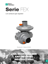
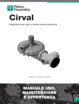
1.2 FUNZIONAMENTO
In assenza di pressione l’otturatore 3 è mantenuto in
posizione di apertura dalla molla 41 (fig. 1).
La pressione di valle Pa viene controllata mediante il
confronto fra il carico della molla 43 e la spinta che la
pressione di valle stessa esercita sulla membrana 19. In
questo confronto intervengono inoltre il peso dell’equi-
paggio mobile, la spinta derivante dalla molla di traino
41 e le spinte dinamiche sull’otturatore.
La pressione di monte, anche se variabile, non ha alcu-
na influenza sull’equilibrio dell’otturatore 3, poiché esso
per la presenza del foro A, viene a trovarsi tra due pres-
sioni uguali agenti su uguali superfici. Il movimento
della membrana 19 viene trasmesso tramite il sistema
di leverismi 13, allo stelo 9 e quindi all’otturatore 3. La
molla 41 ha la funzione di annullare gli inevitabili giochi
del sistema di leverismi 13.
L’otturatore è provvisto di una guarnizione in gomma
vulcanizzata 11 per assicurare la perfetta tenuta quando
la portata richiesta è nulla.
La regolazione si ottiene quindi dal confronto tra il cari-
co della molla di taratura 43 e la spinta sulla membrana
The scope of this manual is to provide essential infor-
mation for the installation, commissioning, disassem-
bly, re-assembly and maintenance of the DIVAL 160 AP
regulator. At the same time we consider it appropriate
to provide a brief illustration of the main features of the
regulator and its accessories.
1.1 MAIN FEATURES
The DIVAL 160 AP is a pressure regulator for previou-
sly cleaned gaseous fluids, and is suitable for medium
pressures.
The DIVAL 160 AP is a normally open regulator and
consequently opens in the event of
- breakage of the main diaphragm
- no regulated pressure signal
The main features of this regulator are:
• design pressure: 85 bar
• operation temperature range: -20°C +60°C
• ambient temperature: -20°C +60°C
• inlet pressure range bpe: 1 ÷ 85 bar
• possible regulating range Wh: 1 ÷ 4.5 bar
• precision class RG: up to 5
• closing pressure class SG: up to 10
1.2 OPERATION
If there is no pressure, the obturator 3 is maintained in
the open position by the spring 41 (fig. 1).
The downstream pressure Pa is controlled by the con-
trast between the load of the spring 43 and the thrust
that the downstream pressure exerts on the diaphragm
19.
The weight of the mobile assembly, the thrust deriving
from the spring 41 and the dynamic thrusts on the
obturator also contribute to this contrast.
Even if variable, the upstream pressure has no effect on
the equilibrium of the obturator 3, because as a result
of the presence of the hole A, it finds itself between two
equal pressures acting on equal surfaces. The move-
ment of the diaphragm 19 is transmitted by means of a
system of levers 13, to the stem 9 and hence to the
obturator 3.
The function of the spring 41 is to eliminate the inevi-
table play in the lever system 13. The obturator is fitted
with a gasket in vulcanised rubber 11 to ensure a per-
fect seal when a zero flow rate is requested.
The regulation is obtained therefore from the contrast
TECHNICAL MANUAL MT059
5
1.0 INTRODUZIONE 1.0 INTRODUCTION

MANUALE TECNICO MT059
19 derivante dalla pressione di valle. Se, per esempio,
durante il funzionamento c’è una diminuzione della
pressione di valle Pa al di sotto del valore di taratura
(per aumento della portata richiesta o diminuzione della
pressione a monte) si instaura uno sbilanciamento che
provoca l’apertura dell’otturatore 3 e quindi un aumen-
to di portata fino a che la pressione di valle raggiunge
nuovamente il valore di taratura impostato.
Viceversa quando il valore della pressione di valle cre-
sce oltre il valore di taratura (per diminuzione della
portata richiesta) si provoca la chiusura dell’otturatore
3 e quindi una diminuzione di portata fino a che la pres-
sione di valle raggiunge nuovamente il valore di taratu-
ra.
In condizioni di normale esercizio l’otturatore 3 si posi-
zione in modo tale da mantenere la pressione Pa attor-
no al valore di taratura prescelto.
Per la regolazione della pressione di taratura basta agire
opportunamente sulla vite di 29 in senso orario per
aumentarla, e viceversa per diminuirla.
La molla 42 ha lo scopo di eliminare gli effetti dannosi
all’otturatore 3 che potrebbero derivare da accidentali
between the load of the setting spring 43 and the thru-
st on the diaphragm 19 deriving from the pressure
downstream. If, for example, the downstream pressure
Pa drops below the set-point during operation (becau-
se of an increased flow rate demand or a drop in the
pressure upstream) an imbalance is created which cau-
ses the obturator 3 to open and therefore increases the
flow rate until the downstream pressure once again
returns to the set-point.
Vice versa, when the downstream pressure value rises
beyond the set-point (because of a drop in the reque-
sted flow rate) it causes the obturator 3 to close and
therefore reduces the flow rate until the downstream
pressure returns to the set-point again. In normal
working conditions, the obturator 3 positions itself so as
to maintain the pressure Pa around the selected set-
point.
The pressure set-point can be adjusted simply by tur-
ning the screw 29 clockwise to increase it and vice
versa to reduce it.
The function of the spring 42 is to eliminate the harm-
ful effects of the obturator 3 which could derive from
accidental overpressures below the diaphragm 19.
TECHNICAL MANUAL MT059
6
Fig. 1
1
1

MANUALE TECNICO MT059 TECHNICAL MANUAL MT059
7
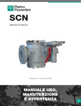
1.3 TAB. 1 Molle di taratura
1 2702940 BIANCO - WHITE 7 6.50 8.50 0.85 ÷ 1.15
2 2703125 GIALLO - YELLOW 7.5 6.25 8.50 1.1 ÷ 1.45
3 2703325 ARANCIO - ORANGE 65 150 8 6.75 9 1.4 ÷ 1.8
4 2703490 ROSSO - RED 8.5 6.25 8.25 1.75 ÷ 2.45
5 2703685 VERDE - GREEN 9 5.75 8 2.4 ÷ 3.3
6 2703995 NERO - BLACK 9.5 6.25 8.25 3.3 ÷ 4.5
De = Ø esterno d = Ø filo i= n. spire utili Lo = Lunghezza molla libera it = n. spire totali
De = Ø external diameter d = Ø wire diameter i= active coils Lo = Length it = total coils
Caratteristiche molla CAMPO DI TARATURA in bar
Springs characteristics SETTING RANGE in bar
Codice Colore De Lo d i it
Code Colour
1.3 TAB. 1 Setting springs

MANUALE TECNICO MT059
2.1 GENERALITÀ
Prima di installare il regolatore è necessario assicurar-
si che:
a) il regolatore sia inseribile nello spazio previsto e sia
sufficientemente agibile per le successive operazio-
ni di manutenzione;
b) le tubazioni di monte e di valle siano al medesimo
livello e in grado di sopportare il peso del regolatore;
c) le flange di entrata/uscita della tubazione siano
parallele;
d) le flange di entrata/uscita del regolatore siano pulite
e il regolatore stesso non abbia subito danni duran-
te il trasporto;
e) la tubazione a monte sia stata pulita eliminando le
impurità residue quali scorie di saldatura, sabbia,
residui di vernice, acqua, ecc...
La disposizione normalmente prescritta è:
TAB. 2
2.1 GENERAL
Before installing the regulator you must ensure that:
a) the regulator can be inserted into the space provi-
ded and that it is sufficiently accessible for subse-
quent maintenance operations;
b) the piping upstream and downstream are at the
same level and able to support the weight of the
regulator;
c) the inlet/outlet flanges on the piping are parallel;
d) the inlet/outlet flanges on the regulator are clean
and the regulator itself has not been damaged
during transport;
e) the piping upstream has been cleaned with the
removal of residual impurities such as welding slag,
sand, paint residues, water, etc.
The normally recommended set-ups are:
TAB. 2
TECHNICAL MANUAL MT059
8
2.0 INSTALLAZIONE 2.0 INSTALLATION
Fig. 2 (Regolatore Standard) Fig. 2 (Standard Regulator)
Fig. 3 (Regolatore capovolto) Fig. 3 (Overturned Regulator)

MANUALE TECNICO MT059
TAB. 3 COLLEGAMENTO APPARECCHIATURE
INSTALLAZIONE IN LINEA
TAB. 3 CONNECTING THE APPARATUSES
IN-LINE INSTALLATION
TECHNICAL MANUAL MT059
9
Regolatore
Regulator
Presa d’impulso
Sensing line
Manometro di controllo
Control pressure gauge
Rubinetto di sfiato
Bleed cock
Valvola di intercettazione
On/Off valve
INSTALLAZIONE A SQUADRA INSTALLATION AT RIGHT ANGLES
Regolatore
Regulator
Presa d’impulso
Sensing line
Manometro di controllo
Control pressure gauge
Rubinetto di sfiato
Bleed cock
Valvola di intercettazione
On/Off valve

MANUALE TECNICO MT059
TAB. 4 PARTICOLARE PRESA MULTIPLA TAB. 4 DETAIL OF MULTIPLE TAKE-OFF
TECHNICAL MANUAL MT059
10
The regulator must be installed in the line with the
arrow on the body pointing in the gas flow direction.
It is indispensable for good regulation for the position
of the downstream pressure take-offs and the speed of
the gas at the take-off point to respect the values given
in tables 3 and 4 (positioning) and 5 (speed).
The following are recommended so as to prevent the
accumulation of impurities and condensate in the lines
of the pressure take-offs:
a) the lines themselves must slope down towards the
downstream piping with a slope of about 5-10%;
b) the connectors on the piping must always be welded
on the top of the piping itself and there must be no burr
or inward protrusions in the hole in the piping.
NB. DO NOT PUT ON/OFF VALVES ON THE IMPUL-
SE TAKE-OFFS
Il regolatore va installato sulla linea orientando la frec-
cia sul corpo nel senso del flusso del gas.
Per ottenere una buona regolazione è indispensabile
che la posizione delle prese di pressione di valle e la
velocità del gas nel punto di presa rispettino i valori
indicati sulle tabelle 3 e 4 (posizionamento) e 5 (velo-
cità).
Allo scopo di evitare il raccogliersi di impurità e con-
dense nei tubi delle prese di pressione si consiglia:
a) che i tubi stessi siano sempre in discesa verso l’at-
tacco della tubazione di valle con una pendenza
all’incirca del 5-10%;
b) che gli attacchi della tubazione siano sempre salda-
ti sulla parte superiore della tubazione stessa e che
il foro sulla tubazione non presenti bave o sporgen-
ze verso l’interno.
NB. NON INTERPORRE VALVOLE DI INTERCETTA-
ZIONE SULLE PRESE DI IMPULSO

MANUALE TECNICO MT059
TAB. 5
Nella tubazione a valle del regolatore la
velocità del gas non deve superare
i seguenti valori:
Vmax = 25 m/s per 1,5 < Pa < 4 bar
Vmax = 20 m/s per 0,5 < Pa < 1,5 bar
VOLUME A VALLE NECESSARIO ALL’INSTALLAZIONE
In caso di impiego del regolatore in servizio di tipo ON-
OFF (arresto od avviamento di bruciatori), si deve tener
presente che l’apparecchio DIVAL, pur essendo classi-
ficato del tipo “a rapida reazione”, richiede un volume di
gas tra l’apparecchio stesso e il bruciatore opportuna-
mente dimensionato, al fine di ammortizzare in parte le
escursioni di pressione provocate da rapide variazioni
di portata.
TAB. 5
The speed of the gas must not exceed the
following values in the piping downstream
from the regulator:
Vmax = 25 m/s per 1,5 < Pa < 4 bar
Vmax = 20 m/s per 0,5 < Pa < 1,5 bar
DOWNSTREAM VOLUME REQUIRED FOR INSTALLATION
In the case of the use of a service regulator of the ON-
OFF type (stopping or starting of burners), you should
remember that though the DIVAL apparatus is classi-
fied as being of the fast reaction type, it requires an
appropriately dimensioned volume of gas between the
apparatus itself and the burner so as to partly absorb
the pressure swings caused by fast flow rate variations.
TECHNICAL MANUAL MT059
11

MANUALE TECNICO MT059 TECHNICAL MANUAL MT059
12
3.0 ACCESSORI 3.0 ACCESSORIES
3.1 VALVOLA DI SFIORO
La valvola di sfioro è un dispositivo di sicurezza che
provvede a scaricare all’esterno una certa quantità di
gas quando la pressione nel punto di controllo supera
quella di taratura a causa di eventi non duraturi, quali
per esempio, la chiusura di valvole di intercettazione in
un tempo molto ridotto e/o un surriscaldamento del gas
con portata richiesta nulla. Lo scarico del gas all’ester-
no può, per esempio ritardare o evitare l’intervento del
dispositivo di blocco per cause transitorie derivanti da
danni al regolatore.
Ovviamente la quantità di gas scaricata dipende dall’en-
tità della sovrapressione rispetto alla taratura. I diversi
modelli di valvole di sfioro disponibili si basano tutti
sullo stesso principio di funzionamento, che viene in
seguito illustrato facendo riferimento alla valvola
VS/AM 56 (fig. 4).
Esso si fonda sul confronto tra la spinta sulla membrana
24 derivante dalla pressione del gas da controllare e la
spinta derivante dalla molla di taratura 18. In questo con-
fronto intervengono il peso dell’equipaggio mobile, le
spinte statiche e quelle dinamiche residue sull’otturatore 4.
Quando la spinta derivante dalla pressione del gas supe-
ra quella della molla di taratura, l’otturatore 4 viene solle-
vato con conseguente scarico di una certa quantità di gas.
Non appena la pressione scende al di sotto del valore di tara-
tura, l’otturatore ritorna in posizione di chiusura. Il controllo
e la registrazione dell’intervento della valvola di sfioro può
essere eseguito seguendo le procedure di seguito indicate.
3.1 RELIEF VALVE
The relief valve is a safety device which releases a cer-
tain quantity of gas to the exterior when the pressure at
the control point exceeds the set-point as a result of
short-lasting events such as, for example, the very fast
closing of the on/off valves and/or overheating of the
gas with zero flow rate demand. The release of the gas
to the exterior can, for example, delay or block inter-
vention of the slam-shut valve for transitory reasons
deriving from damage to the regulator.
Obviously the quantity of gas released depends on the
extent of the overpressure with respect to the set-point.
The different models of relief valve available are all
based on the same operating principle which is illustra-
ted below with reference to the valve VS/AM 56 (fig. 4).
It is based on the contrast between the thrust on the
diaphragm 24 deriving from the pressure of the gas to
control and the thrust from the setting spring 18. The
weight of the mobile assembly, the static thrust and the
residual dynamic thrust on the obturator 4 also contri-
bute to this contrast.
When the thrust deriving from the pressure of the gas
exceeds that of the setting spring, the obturator 4 is
raised and a certain quantity of gas is released as a
result.
As soon as the pressure drops below the set-point, the
obturator returns to the closed position. Proceed as
indicated below to control and adjust intervention of
the relief valve.
Fig. 4

MANUALE TECNICO MT059
3.1.1 INSTALLAZIONE DIRETTA SULLA LINEA
(Fig. 5)
Quando la valvola di sfioro è montata direttamente sulla
linea, senza cioè l’interposizione di una valvola di inter-
cettazione, si consiglia di procedere come indicato di
seguito:
1) assicurarsi che la valvola di intercettazione di valle
V2 e il rubinetto di sfiato 6 siano chiusi;
2) aumentare la pressione nel tronco di valle fino al
valore previsto di intervento collegando al rubinetto
6 una pressione ausiliaria controllata e stabilizzarla al
valore desiderato;
3) verificare l’intervento della valvola di sfioro ed even-
tualmente registrarlo ruotando opportunamente il
tappo di regolazione 13 (in senso orario per aumen-
tare la taratura, e viceversa per diminuirla).
3.1.1 DIRECT INSTALLATION ON THE LINE
(Fig. 5)
When the relief valve is fitted directly in the line without,
that is, the interposition of an on/off valve, we recom-
mend proceeding as follows:
1) ensure that the downstream on/off valve V2 and the
bleed cock 6 are closed;
2) increase the pressure in the downstream section to
the value at which intervention should occur by con-
necting a controlled auxiliary pressure to the cock 6
and stabilise it at the desired value;
3) check intervention of the relief valve and adjust it if
necessary by turning the adjustment plug 13 appro-
priately (clockwise to increase the set-point, anti-
clockwise to reduce it).
TECHNICAL MANUAL MT059
13
3.1.2 INSTALLAZIONE CON VALVOLA DI
INTERCETTAZIONE (Fig. 6)
1) chiudere la valvola di intercettazione 16;
2) collegare alla presa 17 una pressione ausiliaria con-
trollata e aumentarla lentamente fino al valore previ-
sto di intervento;
3) verificare l’intervento della valvola di sfioro ed even-
tualmente registrarlo ruotando opportunamente il
tappo di regolazione 13 (in senso orario per aumen-
tare la taratura, e viceversa per diminuirla).
3.1.2 INSTALLATION WITH ON/OFF VALVE
(Fig. 6)
1) close the on/off valve 16;
2)connect a controlled auxiliary pressure to the take-
off 17 and increase it slowly to the envisaged inter-
vention value;
3)check the intervention of the relief valve and adjust it
if necessary by turning the adjustment plug 13 app-
ropriately (clockwise to increase the set-point, anti-
clockwise to reduce it).
Fig. 5 Fig. 6

MANUALE TECNICO MT059
La concezione di tipo modulare dei regolatori della serie
DIVAL assicura la possibilità di applicare la valvola di
blocco incorporata allo stesso corpo anche in tempi
successivi all’installazione del regolatore.
4.1 VALVOLA DI BLOCCO INCORPORATA
SB 87
E’ un dispositivo (fig. 7) che blocca immediatamente il
flusso del gas se, a causa di qualche guasto, la pres-
sione di valle raggiunge il valore prefissato per il suo
intervento.
Le principali caratteristiche di tale dispositivo di blocco
sono:
• pressione di progetto: 75 bar per tutti i
componenti;
• intervento per incremento e/o diminuzio-
ne della pressione;
• precisione (AG): ± 5% sul valore della
pressione di taratura per aumenti di
pressione, ± 15% per diminuzioni di
pressione;
• by-pass incorporato per ottenere l’equili-
brio delle pressioni ed agevolare il riar-
mo del dispositivo.
The modular-type conception of DIVAL series regula-
tors means that it is also possible to fit the slam-shut
incorporated with the body itself even after the installa-
tion of the regulator.
4.1 INCORPORATED SLAM-SHUT SB 87
This is a device (fig. 7) which immediately blocks the
gas flow if, following some kind of failure, the down-
stream pressure reaches the set-point for its interven-
tion or if it is operated manually.
The main characteristics of the slam-shut device are:
• design pressure: 75 bar for all the
components;
• intervention with pressure increase
and/or decrease;
• precision (AG): ± 5% of the pressure
set-point for pressure increases,
± 15% for pressure decreases;
• incorporated by-pass for balancing
the pressures and facilitating resetting
of the device.
TECHNICAL MANUAL MT059
14
4.0 MODULARITÀ 4.0 MODULARITY
Fig. 7

MANUALE TECNICO MT059
La valvola di blocco SB 87 è costituita essenzialmente
da un otturatore 7 montato su uno stelo 5, da un leve-
rismo di sgancio 23, da una testata di comando C, e da
un sistema di riarmo manuale .
Nella camera C della testata di comando la pressione da
controllare Pa agisce sulla membrana 4, che è solidale
con l’alberino fornito di camme.
Il carico della pressione Pa sulla membrana è contra-
stato dalle molle 35 e 36, che determinano, rispettiva-
mente, l’intervento per aumento o diminuzione di
pressione.
La taratura del dispositivo viene effettuata agendo sulle
ghiere 29 e 30. Una rotazione in senso orario delle ghie-
re provoca un aumento del valore di intervento; vicever-
sa per una rotazione in senso antiorario.
In caso di intervento per aumento di pressione, quando
la Pa supera il valore di taratura il carico sulla membra-
na 4 aumenta fino a vincere la resistenza della molla 35.
Questo provoca la traslazione verso il basso dell’alberi-
no 24, che per mezzo della camma sposta il tastatore
sganciando il leverismo 23. In questo modo si libera lo
stelo 5 con l’otturatore 7 che viene portato in chiusura
dalla molla 38.
L’intervento per diminuzione di pressione avviene invece
nel seguente modo. Fintantoché il valore di Pa rimane al
di sopra del carico di taratura della molla 36 il supporto
molla 26 rimane in appoggio sul supporto 27.
Se la pressione Pa diminuisce al di sotto del valore pre-
fissato, la molla 36 fa traslare verso l’alto il supporto 26
e di conseguenza l’alberino 24.
La camma sposta quindi il tastatore provocando lo
sgancio del leverismo 23. Il riarmo del blocco si esegue
svitando la bussola filettata 6 e tirandola verso il basso
fino a riagganciare il leverismo 23.
Nella prima fase della manovra, sarà necessario atten-
dere che la pressione di monte, attraverso il by-pass
interno, passi a valle dell’otturatore equilibrandolo.
Dopo il riarmo la bussola 6 dovrà essere riavvitata nella
sua sede. La condizione di apertura o chiusura della val-
vola di blocco è individuabile dall’esterno osservando la
posizione del dado 50 attraverso la feritoia della
bussola 6.
Il collegamento tra la testata di comando C e il punto di
controllo della Pa può avvenire con l’interposizione di un
dispositivo (Push) fig. 12 che consente un facile con-
trollo della funzionalità del dispositivo pressostatico.
The SB 87 slam-shut consists essentially of an obtura-
tor 7 fitted on a rod 5, a release lever assembly 23, a
control head C and a manual resetting system.
In the chamber C of the control head, the pressure to
control Pa acts on the diaphragm 4 which is integral
with the shaft with cams.
The load of the pressure Pa on the diaphragm is con-
trasted by the springs 35 and 36, which respectively
determine intervention for a pressure increase or
decrease.
The device is set by adjusting the rings 29 and 30. The
intervention value is increased by turning the rings
clockwise and vice versa when turned anticlockwise.
In the case of intervention for pressure increase, when
the Pa exceeds the set-point, the load on the diaphragm
4 increases until it overcomes the resistance of the
spring 35.
This provokes the downward displacement of the shaft
24 which shifts the feeler and releases the lever mecha-
nism 23 by means of the cam. In this way, the rod 5 is
released with the obturator 7 which is closed by the
spring 38.
Intervention for a pressure decrease takes place as fol-
lows. As long as the value of Pa stays above the set
load of the spring 36, the spring support 26 rests on
support 27.
If the pressure Pa drops below the set-point, the spring
36 displaces the support 26 upwards and the shaft 24
as a result.
The cam then shifts the feeler and causes the release of
the lever mechanism 23. The slam-shut is re-armed by
unscrewing the threaded bushing 6 and pulling it
downwards until the lever mechanism 23 is rearmed.
During the first stage of this operation, you must wait
until the pressure upstream from the obturator passes
downstream through the internal by-pass and
rebalances it.
After re-arming, you must screw the bushing 6 back in
its seat. It is possible to see from outside if the slam-
shut is open or closed by observing the position of the
nut 50 through the slot in the bushing 6.
The connection between the control head C and Pa
control point can be made with the interposition of a
device (Push) fig. 12 which makes it easy to control the
operation of the pressure control device.
TECHNICAL MANUAL MT059
15

9 2700513 ROSSO - RED 2 8.50 10.50 0.07 ÷ 0.19
10 2700713 VERDE - GREEN 2.3 8.50 10.50 0.17 ÷ 0.03
11 2700750 NERO - BLACK 2.5 6.50 8.25 0.27 ÷ 0.7
12 2700985 GIALLO - YELLOW 15 40 3 6 8 0.68 ÷ 1
13 2700513 ROSSO -RED 2 8.50 10.50 0.4 ÷ 1
14 2700713 VERDE - GREEN 2.3 8.50 10.50 1 ÷ 1.9
15 2700750 NERO - BLACK 2.5 6.50 8.25 1.8 ÷ 2.8
16 2700985 GIALLO - YELLOW 3 6 8 2.7 ÷ 5
MANUALE TECNICO MT059 TECHNICAL MANUAL MT059
16
4.2 TAB. 6 MOLLE DI TARATURA BLOCCO 4.2 TAB. 6 SLAM-SHUT SETTING SPRINGS
De = Ø esterno d = Ø filo i= n. spire utili Lo = Lunghezza molla libera it = n. spire totali
De = Ø external diameter d = Ø wire diameter i= active coils Lo = Length it = total coils
1 2701040 BIANCO - WHITE 3 5.5 7.5 0.15 ÷ 0.26
ARANCIO - ORANGE
2 2701260 BIANCO - WHITE 35 60 3.5 5.5 7.5 0.25 ÷ 0.54
3 2701530 GIALLO - YELLOW 4 5 7 0.53 ÷ 0.95
4 2701790 GIALLO - YELLOW 4.5 4.5 6.5 0.92 ÷ 1.5
NERO - BLACK
5 2701142 BIANCO - WHITE 3.25 5.5 8 1 ÷ 1.4
GIALLO - YELLOW
6 2701260 BIANCO - WHITE 35 60 3.5 5.5 7.5 1.3 ÷ 2.1
7 2701530 GIALLO - YELLOW 4 5 7 2 ÷ 3.7
8 2701790 GIALLO - YELLOW 4.5 4.5 6.5 3.8 ÷ 6.8
NERO - BLACK
CAMPO DI TARATURA in bar
SETTING RANGE in bar
Caratteristiche molla/Springs characteristics SB 87/102 SB 87/103
Codice Colore De Lo d i it max min max min
Code Colour

MANUALE TECNICO MT059
Il monitor è un regolatore di emergenza che ha il com-
pito di entrare in servizio al posto del regolatore princi-
pale qualora questo, per una sua anomalia, consenta
alla pressione di valle di raggiungere il valore di taratu-
ra fissato per l’intervento del monitor.
Per tale dispositivo di emergenza la PIETRO FIORENTI-
NI dispone di una soluzione per installazioni con moni-
tor in linea (fig. 8) .
4.3.1 CARATTERISTICHE
• ingombro ridotto;
• semplicità di manutenzione.
The monitor is an emergency regulator whose function
is to come into service instead of the main regulator
when failure of the latter allows the downstream pres-
sure to reach the point set for monitor intervention.
PIETRO FIORENTINI has a solution for this emergency
device for installations with in-line monitor (fig. 8).
4.3.1 CHARACTERISTICS
•reduced dimensions;
•easy maintenance.
TECHNICAL MANUAL MT059
17
4.3 DIVAL AP CON FUNZIONAMENTO DA
MONITOR
4.3 DIVAL AP FUNCTIONING AS MONITOR
Fig. 8

MANUALE TECNICO MT059
5.1 GENERALITÀ
Dopo l’installazione verificare che le valvole di intercet-
tazione di entrata/uscita, l’eventuale by-pass e il rubi-
netto di sfiato siano chiusi.
Si raccomanda di verificare, prima della messa in servi-
zio, che le condizioni di impiego siano conformi alle
caratteristiche delle apparecchiature.
Tali caratteristiche siano richiamate con i simboli sulle
targhette di cui ogni apparecchiatura è munita.
Si raccomanda di azionare le valvole di apertura e chiu-
sura molto lentamente. Manovre troppe rapide potreb-
bero danneggiare il regolatore.
5.0 MESSA IN SERVIZIO 5.0 START UP
TECHNICAL MANUAL MT059
18
REGULATOR: T:
S.n.: Pzul: Pemax:bar bar
DN: Flange: RG:
Wh: Bpe:bar bar SG:
Wa: bar Fluido: Cg:
DIVAL 160 AP -10 + 60° C
2000AA0021 46,8 46,8
1” S300 SMOOTH FINISH 1,5
0,85/4,5 22,0/23,00 2,5
1,75/2,45 METANO /
SLAM SHUT DEVICE:
S.n.:
T:
AG:
AG:
Who:
Wao:
Whu:
Wau:
bar
bar
bar
bar
SB/87 M. 103
2000ZA2327
-10 + 60° C
5
10
1.00/6.80
1.80/2.80
0,40/5.00
0,40/1.00
TARGHETTE APPARECCHIATURE APPARATUS SPECIFICATION PLATES
5.1 GENERAL
After installation, check that the inlet/outlet on/off val-
ves, any by-pass and the bleed cock are closed.
Before commissioning, you must ensure that the con-
ditions of use comply with the characteristics of the
apparatuses.
These characteristics are recalled by the symbols on
the specification plates applied to each apparatus.
We recommend actuating the opening and closing val-
ves very slowly. The regulator could be damaged by
operations which are too fast.

MANUALE TECNICO MT059
Di seguito è riportato l’elenco dei simboli usati e il loro
significato:
Pemax= massima pressione di funzionamento
all’entrata dell’apparecchio
bpe= campo di variabilità della pressione di entrata del
regolatore di pressione in condizioni di normale funzio-
namento
Pzul= massima pressione che può essere sopportata in
condizioni di sicurezza dalla struttura del corpo dell’appa-
recchio
Wa= campo di taratura del regolatore di pressione/
pilota/preriduttore che può essere ottenuto usando i
particolari e la molla di taratura montati al momento del
collaudo (non cambiando cioè alcun componente del-
l’apparecchio). Nei regolatori pilotati il pilota viene con-
siderato come apparecchiatura separata con proprio
campo di taratura Wa
Wh= campo di taratura del regolatore di pressione/pilo-
ta/preriduttore che può essere ottenuto usando le molle
di taratura indicate nelle apposite tabelle ed eventual-
mente cambiando qualche altro particolare dell’appa-
recchio (pastiglia armata, membrane, ecc.). Nei regola-
tori pilotati il pilota viene considerato come apparec-
chiatura separata con proprio campo di taratura Wh
QmxPemin= portata massima con la pressione minima
all’entrata del regolatore di pressione
QmxPemax= portata massima con la pressione massi-
ma all’ingresso del regolatore di pressione
Cg= coefficiente sperimentale di portata critica
RG= classe di regolazione
SG= classe di pressione di chiusura
AG= precisione di intervento
Wao= campo di intervento per sovrapressione di valvo-
le di blocco, sfioro e di sicurezza e acceleratori che può
essere ottenuto usando la molla di taratura montata al
momento del collaudo. Nelle valvole di sicurezza pilota-
te il pilota viene considerato come apparecchiatura
separata con proprio campo di taratura Wao
Who= campo di intervento per sovrapressione di valvo-
le di blocco, sfioro e di sicurezza e acceleratori che può
essere ottenuto usando le molle di taratura indicate
nelle tabelle. Nelle valvole di sicurezza pilotata il pilota
viene considerato come apparecchiatura separata con
proprio campo di taratura Who
Wau= campo di intervento per diminuzione di pressio-
ne di valvole di blocco che può essere ottenuto usando
la molla di taratura montata al momento del collaudo
Whu= campo di intervento per diminuzione di pressio-
ne di valvole di blocco che può essere ottenuto usando
le molle di taratura indicate nelle tabelle.
The list of symbols used and their meanings are listed
below:
Pemax= maximum inlet operating pressure of the
apparatus
bpe= range of variability of the inlet pressure of the
pressure regulator in normal operating conditions
Pzul= maximum pressure which can be supported by
the structure of the body of the apparatus in safety con-
ditions
Wa= range of setting of the pressure regulator/
pilot/pre-regulator which can be obtained using the
parts and the setting spring fitted at the moment of
testing (without changing any components of the appa-
ratus, that is). In the piloted regulators, the pilot is con-
sidered as a separate apparatus with its own setting
range Wa
Wh= range of setting of the pressure regulator/pilot/
pre-regulator which can be obtained using the setting
springs indicated in the associated tables and also by
changing some other part of the apparatus (reinforced
gasket, diaphragm etc.). In the piloted regulators, the
pilot is considered as a separate apparatus with its own
setting range Wh
QmxPemin= maximum flow rate with minimum pres-
sure at the pressure regulator inlet
QmxPemx= maximum flow rate with maximum pres-
sure at the pressure regulator inlet
Cg= experimental coefficient of critical flow
RG= regulation class
SG= closing pressure class
AG= precision of action
Wao= range of operation for the over pressure of slam-
shut, relief and safety valves and accelerators which
can be obtained using the setting spring fitted at the
moment of testing. In the piloted regulators, the pilot is
considered as a separate apparatus with its own setting
range Wao
Who= range of operation for the over pressure of slam-
shut, relief and safety valves and accelerators which
can be obtained using the setting springs indicated in
the tables. In the piloted regulators, the pilot is consi-
dered as a separate apparatus with its own setting
range Who
Wau= range of operation for the reduction of slam-shut
pressure which can be obtained using the setting
spring fitted at the moment of testing
Whu= range of operation for the reduction of slam-shut
pressure which an be obtained using the setting
springs indicated in the tables.
TECHNICAL MANUAL MT059
19

MANUALE TECNICO MT059
5.2 MESSA IN GAS, CONTROLLO TENUTA
ESTERNA E TARATURE
La tenuta esterna è garantita quando, cospargendo l’e-
lemento in pressione con un mezzo schiumogeno, non
si formano rigonfiamenti di bolle.
Il regolatore e le altre eventuali apparecchiature (valvo-
le di blocco, monitor) vengono normalmente forniti già
tarati al valore richiesto. E’ peraltro possibile che per
vari motivi (es. vibrazioni durante il trasporto), le tara-
ture possano subire modifiche, restando in ogni caso
comprese entro i valori consentiti dalle molle utilizzate.
Si consiglia quindi di verificare le tarature secondo le
procedure di seguito illustrate.
Nelle tabelle 7 e 8 sono riportati i valori consigliati di
taratura delle apparecchiature previste nelle diverse
filosofie impiantistiche. I dati di queste tabelle possono
risultare utili sia in fase di verifica delle tarature esi-
stenti, sia in caso di modifica delle stese che dovesse-
ro rendersi necessarie in tempi successivi. Per gli
impianti composti da due linee, si suggerisce di proce-
dere alla messa in servizio di una linea alla volta, ini-
ziando da quella con taratura inferiore cosiddetta “di
riserva”. Per questa linea, i valori di taratura delle
apparecchiature si scosteranno ovviamente da quelli
indicati dalle tabelle 7 e 8.
Prima di procedere alla messa in servizio del regola-
tore è necessario verificare che tutte le valvole di
intercettazione (entrata, uscita, by-pass eventuale)
siano chiuse e che il gas sia a temperatura tale da
non generare disfunzioni.
5.2 GAS INPUT, CONTROL OF EXTERNAL
TIGHTNESS AND SETTING
External tightness is guaranteed if no bubbles form
when a foam medium is applied on the element under
pressure.
The regulator and any other apparatuses (slam-shut,
monitor) are normally supplied already set for the desi-
red set-point. It is possible for various reasons (e.g.,
vibration during transport) for the settings to be chan-
ged while remaining within the values permitted by the
springs used.
We therefore recommend checking the settings using
the procedures illustrated below.
Tables 7 and 8 give the recommended set-points for the
apparatuses in the various installation arrangements.
The figures in these tables can be useful both when
checking existing set-points and for modifying them
should this become necessary later.
In installations consisting of two lines, we suggest
commissioning one line at a time, starting from the one
with the lower set-point, known as the "reserve" line.
The set-points of the apparatuses in this line will
obviously deviate from those specified in the tables 7
and 8.
Before commissioning the regulator you must check
that all the on/off valves (inlet, outlet, any by-pass)
are closed and that the gas is at a temperature which
will not lead to malfunction.
TECHNICAL MANUAL MT059
20
1/44