Trox X-CUBE X2 Istruzioni per l'uso
- Categoria
- Antincendio
- Tipo
- Istruzioni per l'uso
Questo manuale è adatto anche per

Air handling units
X-CUBE CONTROL 2
Operating manual
Read the instructions prior to performing any task!
Controls visualisation for air handling units
GB/en

A00000093796, 2, GB/en
© TROX GmbH 2022
TROX GmbH
Heinrich-Trox-Platz
47504 Neukirchen-Vluyn, Germany
Germany
Phone: +49 (0) 2845 2020
Fax: +49 2845 202-265
E-mail: [email protected]
Internet: http://www.troxtechnik.com
08/2022
Air handling units X-CUBE CONTROL 22

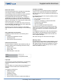
About this manual
This manual describes how to operate the air handling
unit using the controls visualisation software.
This operating manual is intended for use by operators
(instructed persons) and network administrators.
It is essential that instructed persons (
Ä
Chapter 1.1
‘Qualification’ on page 6 ) read and fully understand
this manual before starting any work. The basic prereq-
uisite for safe working is to comply with the safety notes
and all instructions in this manual.
The local regulations for health and safety at work and
the general safety regulations for the area of application
of the air handling unit also apply.
Illustrations in this manual are mainly for information
and may differ from the actual design of the air handling
unit.
Other applicable documentation
In addition to these instructions, the following docu-
ments apply:
Transport and installation manual
Operating manual
Order-specific approval drawing
TROX Technical Service
To ensure that your request is processed as quickly as
possible, please keep the following information ready:
Product name
TROX order number
Delivery date
Brief description of the fault
Online www.trox.de
Phone +49 (0) 2845 202400
Copyright
This document, including all illustrations, is protected by
copyright and pertains only to the corresponding
product.
Any use without our consent may be an infringement of
copyright, and the violator will be held liable for any
damage.
This applies in particular to:
Publishing content
Copying content
Translating content
Microcopying content
Saving content to electronic systems and editing it
Limitation of liability
The information in this manual has been compiled with
reference to the applicable standards and guidelines,
the state of the art, and our expertise and experience of
many years.
The manufacturer does not accept any liability for dam-
ages resulting from:
Non-compliance with this manual
Incorrect use
Operation or handling by untrained individuals
Unauthorised modifications
Technical changes
Use of non-approved replacement parts
The actual scope of delivery may differ from the infor-
mation in this manual for bespoke constructions, addi-
tional order options or as a result of recent technical
changes.
The obligations agreed in the order, the general terms
and conditions, the manufacturer's terms of delivery,
and the legal regulations in effect at the time the con-
tract is signed shall apply.
We reserve the right to make technical changes.
Warranty claims
The provisions of the respective general delivery terms
apply to warranty claims. For purchase orders placed
with TROX GmbH, these are the regulations in section
"Vl. Warranty claims" of the Delivery Terms of TROX
GmbH, see www.trox.de/en/ .
Supplemental directives
Air handling units X-CUBE CONTROL 2 3

Safety notes
Symbols are used in this manual to alert readers to
areas of potential hazard. Signal words express the
degree of the hazard.
Comply with all safety instructions and proceed carefully
to avoid accidents, injuries and damage to property.
DANGER!
Imminently hazardous situation which, if not avoided,
will result in death or serious injury.
WARNING!
Potentially hazardous situation which, if not avoided,
may result in death or serious injury.
CAUTION!
Potentially hazardous situation which, if not avoided,
may result in minor or moderate injury.
NOTICE!
Potentially hazardous situation which, if not avoided,
may result in property damage.
ENVIRONMENT!
Environmental pollution hazard.
Tips and recommendations
Useful tips and recommendations as well as informa-
tion for efficient and fault-free operation.
Specific safety notes
The following symbols are used in safety notes to alert
you to specific hazards:
Warning signs Type of danger
Warning – danger zone.
Additional markers
In order to highlight instructions, results, lists, refer-
ences and other elements, the following markers are
used in this manual:
Marker Explanation
1., 2., 3. ...
Step-by-step instructions
ðResults of actions
References to sections in this
manual and to other applicable
documents
Lists without a defined sequence
[Switch] Operating elements (e.g. push but-
tons, switches), display elements
(e.g. LEDs)
‘Display’ Screen elements (e.g. buttons or
menus)
Supplemental directives
Air handling units X-CUBE CONTROL 24

1 Safety ................................................................ 6
1.1 Qualification ............................................... 6
2 Network configuration .................................... 7
2.1 Changing the target address for visualisa-
tion ............................................................. 7
2.2 Changing your own IP address ................. 7
2.3 Visualisation on external devices .............. 7
3 User interface ................................................... 8
3.1 Starting screen .......................................... 8
3.2 State control ........................................ 12
3.3 User management ................................... 14
3.4 Alarm list .................................................. 16
4 General settings ............................................ 18
4.1 Switching the system on/off ..................... 18
4.1.1 Setting holidays .................................... 22
4.1.2 Setting a vacation ................................. 23
4.1.3 Setpoint additional time ........................ 24
4.2 Basic settings .......................................... 25
4.3 Control strategy ....................................... 26
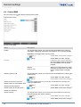
4.4 Central BMS ............................................ 28
4.5 Room control unit .................................... 29
4.6 Setpoint adjustment ................................. 29
4.7 Night purge .............................................. 30
4.8 External alarms ....................................... 30
4.9 External devices ...................................... 31
4.10 Guided operation ................................... 32
4.11 Modbus RTU monitoring ........................ 33
4.12 X-AIRCONTROL ................................... 33
4.13 Network adapter .................................... 34
5 Component status and settings ................... 35
5.1 Exhaust air damper / Outdoor air damper /
Supply air damper / Extract air damper ... 35
5.2 Outdoor air filter, supply air filter, extract
air filter ..................................................... 36
5.3 Supply air fan / extract air fan .................. 37
5.4 Heat recovery wheel ................................ 40
5.5 Plate heat exchanger .............................. 42
5.6 Recirculation damper .............................. 44
5.7 Run around coil ....................................... 46
5.8 Preheater/reheater (hot water) ................ 48
5.9 Electric preheater / electric reheater ....... 51
5.10 Cooler (chilled water) ............................ 52
5.11 External chiller ....................................... 54
5.12 Humidifier .............................................. 56
5.13 Sensors ................................................. 58
5.14 Weather sensor ..................................... 59
5.15 Room sensor ......................................... 60
6 Fire protection ............................................... 62
6.1 TROXNETCOM ....................................... 62
6.2 Smoke detector ....................................... 63
6.3 Fire dampers ........................................... 65
6.4 Assisted smoke extraction ....................... 68
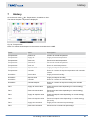
7 History ............................................................ 69
8 Faults .............................................................. 71
8.1 Faults ....................................................... 71
8.2 Alarm list .................................................. 71
9 Change history .............................................. 88
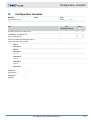
10 Configuration checklist ................................. 89
11 Index................................................................ 90
Table of contents
Air handling units X-CUBE CONTROL 2 5

1 Safety
1.1 Qualification
The work described in this manual has to be carried out
by individuals with the qualification, training, knowledge
and experience described below:
Network administrator
Network administrators design, install, configure and
maintain the IT infrastructure in companies or organisa-
tions.
Operator
Operators have been instructed by the system owner to
enable them to avoid any potential hazards related to
the work under consideration. Operators must not carry
out any jobs beyond regular operation unless explicitly
stated in this manual and unless the system owner has
specifically agreed to them.
Any work has to be carried out by individuals who can
be expected to carry out their assigned duties reliably.
Individuals whose reaction time is delayed due to
alcohol, drugs or other medication must not carry out
any work.
Passwords
The various functions of the visualisation software are
password protected to prevent unauthorised people
from using it.
Every user should have their own, unique user
name and password.
Make sure that each user knows only their own
password.
Do not share your access data with anyone.
Do not use the same access data for both private
and professional purposes.
Do not store passwords on an internet browser.
Store passwords (if you need to store them at all) in
a safe place; use a password manager, for example.
Instruction
System owners must regularly instruct their personnel.
The instruction procedure has to be documented for fur-
ther reference.
At least the following details have to be documented:
Date of instruction
Names of persons being instructed
Type of instruction
Name of instructor
Signature of person being instructed
Safety
Qualification
Air handling units X-CUBE CONTROL 26

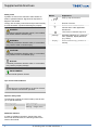
2 Network configuration
The touch panel and X-CUBE Control are factory set in such a way that any visualisation data is displayed on the
touch panel.
Factory setting
Own IP address: 192.168.0.10 or 192.168.0.100
Target address for visualisation: https://192.168.0.180:1020 or
https://192.168.0.200:1020
IMPORTANT
If other IP addresses have been set previously, e.g. as part of commissioning, contact your network administrator.
Use the form in the appendix to document IP addresses and user names,
Ä
Chapter 10 ‘ Configuration check-
list’ on page 89
2.1 Changing the target address for
visualisation
Personnel:
Network administrator
If there is no X-CUBE visualisation (white display or
error message ERR_ADDRESS_UNREACHABLE ), check
whether the correct IP address has been set; if not, cor-
rect it.
1. To show the ‘System menu’ on the touch panel,
swipe from the left edge to the centre.
ðBack with
2. Select ‘Edit profile’ .
3. Select the ‘General’ tab.
Enter the IP address of the X-CUBE controller
(target address of the controls visualisation) as fol-
lows:
https://[IP ADDRESS]:1020
ðApply with .
2.2 Changing your own IP address
Personnel:
Network administrator
Important: This is not the IP address of the X-CUBE
controller.
Changing that address is described in chapter 3.9.2.
1. To show the ‘System menu’ on the touch panel,
swipe from the left to the centre.
ðBack with
2. Select ‘Edit profile’ .
3. Select the ‘Bridge’ tab.
Go to the ‘Start page’ field and enter your own IP
address, also enter the subnet mask of the touch
panel.
ðApply with .
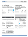
2.3 Visualisation on external devices
You can also use other terminal devices (PC, notebook,
tablet, web browser that supports HTML5) for visualisa-
tion.
Make sure that the terminal device and X-CUBE con-
troller are part of the same network.
We recommend the following browsers:
Mozilla Firefox
Google Chrome
Microsoft Edge
To open the visualisation software, enter the IP address
into the address line of the browser.
https://192.168.0.180:1020 or
https://192.168.0.200:1020
For more information
Ä
‘Factory setting’ on page 7
Network configuration
Visualisation on external devices
Air handling units X-CUBE CONTROL 2 7

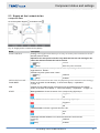
3 User interface
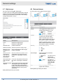
3.1 Starting screen
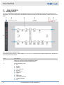
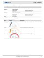
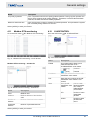
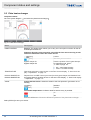
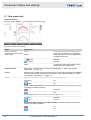
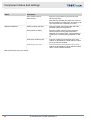
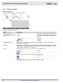
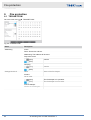
Once the visualisation software has been opened without any errors, the loading progress and the web server ver-
sion appear. The various pages of the visualisation software are loaded to the web browser to enable a smooth navi-
gation.
Fig. 1: Visualisation starting screen
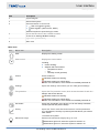
The starting screen displays a system diagram. If you click on a component, the respective page opens. Header and
main menu are always shown.
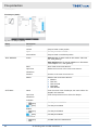
Item Description
1 Select this symbol to display the software version.
TROX Service will ask for the software version.
2 Current operating mode:
Off
Standby
Control
Frost protection
De-icing
Start-up time
Follow up
Hand
Night purge
Intermittent operation
Cooling protection
Fire
User interface
Starting screen
Air handling units X-CUBE CONTROL 28

Item Description
3 System diagram
4 Name of the system
5 Name and status of current user
User not logged in (guest)
User logged in (staff, service, admin)
Select this symbol to open the log-in screen.
6 Shows date and time of the X-CUBE controller,
To set: Go to ‘Settings è Basic settings’ .
7 Light switch (maintenance)
8 Main menu
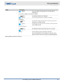
Main menu
Icon Menu item Description
Start Displays the starting screen.
State control Displays the control status.
Including
Control strategy
Setpoint and actual values:
– Temperature control
– Fan
– Humidity control (optional)
Alarms Shows all alarms
Indicates at least one warning.
Indicates at least one critical alarm.
In case of a critical alarm, the X-CUBE is immediately switched off.
Settings Opens the 'Settings' menu where you can make general settings.
Fire protection Opens the 'Fire protection' menu, which shows the status of each fire
damper and smoke detector.
Indicates at least one warning.
Indicates at least one critical alarm.
In case of a critical alarm, the X-CUBE is immediately switched off.
Schedules Opens the 'Schedules' menu where you can set weekly schedules,
vacation periods and public holidays.
History Opens the 'Trend' menu that shows trends for various parameters
(e.g. temperature, humidity or pressure) and that allows you to down-
load* trends.
*not with a touch panel
Maintenance light Switches the maintenance light (if any) on or off.
Maintenance light is off; select this symbol to switch it on
Maintenance light is on; select this symbol to switch it off
User interface
Starting screen
Air handling units X-CUBE CONTROL 2 9

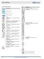
System diagram symbols
Icon Description
Airflow to the left
Airflow to the left
Airflow to the right
Airflow to the right
Cooler
Ä
Chapter 5.10 ‘ Cooler (chilled water)’
on page 52
Damper
Ä
Chapter 5.1 ‘ Exhaust air damper / Out-
door air damper / Supply air damper /
Extract air damper’ on page 35
Left fan
Ä
Chapter 5.3 ‘Supply air fan / extract air
fan’ on page 37
Right fan
Ä
Chapter 5.3 ‘Supply air fan / extract air
fan’ on page 37
Left filter
Ä
Chapter 5.2 ‘ Outdoor air filter, supply
air filter, extract air filter’ on page 36
Right filter
Ä
Chapter 5.2 ‘ Outdoor air filter, supply
air filter, extract air filter’ on page 36
Preheater
Ä
Chapter 5.8 ‘ Preheater/reheater (hot
water)’ on page 48
Reheater
Ä
Chapter 5.8 ‘ Preheater/reheater (hot
water)’ on page 48
Electric preheater
Ä
Chapter 5.9 ‘ Electric preheater / elec-
tric reheater’ on page 51
Electric reheater
Ä
Chapter 5.9 ‘ Electric preheater / elec-
tric reheater’ on page 51
Humidifier
Ä
Chapter 5.12 ‘ Humidifier’
on page 56
Icon Description
Plate heat exchanger
Ä
Chapter 5.5 ‘Plate heat exchanger’
on page 42
Heat recovery wheel
Ä
Chapter 5.4 ‘Heat recovery wheel’
on page 40
Run around coil
Ä
Chapter 5.7 ‘ Run around coil’
on page 46
Orange: Heating energy feed
Blue: Cooling energy feed
User interface
Starting screen
Air handling units X-CUBE CONTROL 210

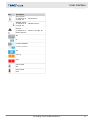
Icon Description
Room sensor
Ä
Chapter 5.15 ‘ Room sensor’
on page 60
Weather sensor
Ä
Chapter 5.14 ‘ Weather sensor’
on page 59
Sensors
Ä
Chapter 5.13 ‘ Sensors’ on page 58
Smoke detector
Off
On
Function disabled
Function enabled
OK
Warning
Error
Hand control
OK
Hand control
Error
User interface
Starting screen
Air handling units X-CUBE CONTROL 2 11

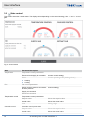
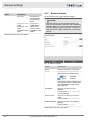
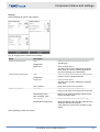
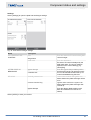
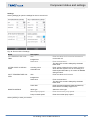
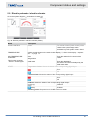
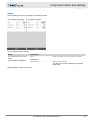
3.2 State control
This screen shows the control status. The display varies depending on the control strategy. Use ‘<’ and ‘>’ to navi-
gate.
Fig. 2: Control status
Area Parameter/description
Temperature Temperature control parameters
Extract air and supply air cascades Current control strategy
Mode:
Heating
Cooling
Current operating mode (heating shown)
Fan Fan control parameters
Supply air duct pressure and extract
air duct pressure
Control strategy
Supply air command
Extract air command
Temperature control Temperature control parameters
Setpoint value Shows the setpoint value
Actual value Shows the actual value
Area Setting range
Cascade control Cascade control parameters
Setpoint value Shows the setpoint value
Actual value Shows the actual value
User interface
State control
Air handling units X-CUBE CONTROL 212

Area Parameter/description
Area Setting range
Supply air Supply air values
Setpoint value Shows the setpoint value
Actual value Shows the actual value
Extract air Shows extract air values
Setpoint value Shows the setpoint value
Actual value Shows the actual value
Close Close window
Semi-circle display – explanation
Colour Display Description
Neutral/grey Normal, error-free control Actual value within defined range
Orange Actual value deviates from setpoint value
Red Actual value exceeds displayed range
User interface
State control
Air handling units X-CUBE CONTROL 2 13

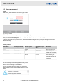
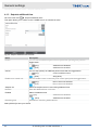
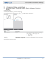
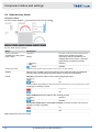
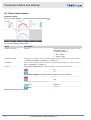
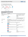
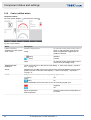
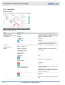
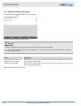
3.3 User management
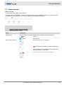
Login
Select the in the header to open the ‘Login’ screen.
Fig. 3: Login screen
Enter your ‘user name’ and ‘password’ , then select [LOGIN].
Also select a display language, either [Deutsch], [English] or [Françai]s; the display language you select will be used
once you are successfully logged in.
If another user wants to log in, the current, active user first has to log out. To log out, open the log-in screen and
select [LOGOUT].
Factory settings
User name Default password Access rights Automatic logout
after …
Activities
Guest - Guest - Read access only
userStaff userStaff Staff 15 minutes Can change set-
points and schedules
userService userService Service 1 hour Can change con-
troller settings,
external devices and
the central BMS
interface
Be sure to change the default login data when you are
commissioning the system to prevent any unauthorised
persons from accessing the visualisation.
As long as you are using the default user name and
default password to log in, the following warning will be
shown:
User interface
User management
Air handling units X-CUBE CONTROL 214

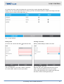
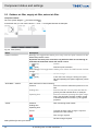
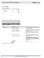
To create a new user or edit an existing user, go to the log-in screen and select [SETTINGS].
Please note: Your access rights allow you to change your own user data as well as to create and change users that
have the same or fewer access rights than you.
Fig. 4: Log-in settings
Editing users
Go to the ‘edit’ column and select to edit user data.
Fig. 5: Editing users
You may change the ‘user name’ and the ‘password’
for a user. Select ‘APPLY’ to save your entries.
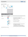
Creating a new user
Select [+ NEW USER] to create a new user.
Fig. 6: Creating a new user
Enter the user name, password and level of access
rights*, then select [APPLY] to save your entries.
Your access rights allow you to create users that have
the same or fewer access rights than you.
User interface
User management
Air handling units X-CUBE CONTROL 2 15

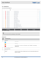
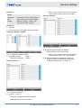
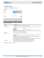
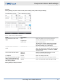
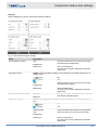
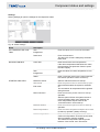
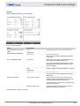
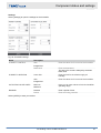
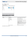
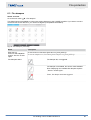
3.4 Alarm list
This screen shows all alarms.
Fig. 7: Alarm overview
You can sort the alarms by selecting a column header.
Explanation
Colu
mn
Icon/description
1 Alarm no.
2 Information
Warning
Critical alarm. In case of a critical alarm, the X-CUBE is immediately
switched off.
3 Time the alarm occurred.
4 Alarm description
5 Alarm ID
History Opens the 'Alarm history' window where you can download the alarm his-
tory as a csv file.
User interface
Alarm list
Air handling units X-CUBE CONTROL 216

Colu
mn
Icon/description
Acknowledge/delete all alarms.
Alarms for unsolved errors will be displayed again after a short while.
This function requires at least 'Staff' access rights.
Close Close window
History
This screen shows the alarm history.
Fig. 8: 'Alarm history' window
To download alarms as csv files, select a history; 'his-
tory #1' shows the newest alarms, 'history #10' shows
the oldest alarms. The alarm history comprises up to
2000 entries with time stamp, error text and priority. If a
logged in user acknowledges or deletes an alarm, this
information will be saved together with the user name.
User interface
Alarm list
Air handling units X-CUBE CONTROL 2 17

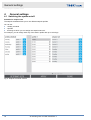
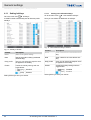
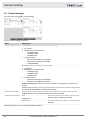
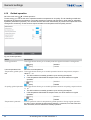
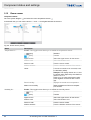
4 General settings
4.1 Switching the system on/off
Schedule for setpoint sets
The setpoint schedule allows you to use different setpoint profiles.
You can set:
1 weekly schedule
7 profiles
10 timings to which you can assign one setpoint set each.
For example, you can assign each day of the week a profile with up to 10 timings.
Fig. 9: 'Setpoint schedule' window
General settings
Switching the system on/off
Air handling units X-CUBE CONTROL 218

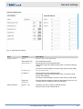
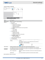
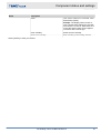
Defining setpoint sets
Fig. 10: 'Setpoint sets' window
Area Parameter Description
Setpoint values Name Enter a name for the setpoint set.
Temperature from Set a temperature range.
Energy-efficient control with dead band:
If this value is within the defined range, there is no active heating or
cooling.
To achieve a certain setpoint, enter the same value into both fields.
Temperature to
Humidity from Set a humidity range.
Energy-efficient control with dead band:
If this value is within the defined range, there is no active humidi-
fying or dehumidifying.
To achieve a certain setpoint, enter the same value into both fields.
Humidity to
Supply fan Enter the setpoint values for supply air and extract air fans in a unit
of measure that is suitable for the control strategy.
Extract fan
External devices Device 1 - 20 Schedules can also be used for external devices.
Enter the value for the external device.
General settings
Switching the system on/off
Air handling units X-CUBE CONTROL 2 19

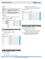
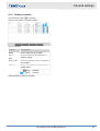
Example 1
Given
Operating
time
- Each working day from 06:00 to
18:00h with the same setpoint
values
Setting - Monday to Friday - profile 1, Sat-
urday and Sunday - profile 2
Personnel:
Operator
1. Go to the main menu è ‘Setpoint schedule’ .
Defining a ‘Weekly schedule’
Fig. 11: 'Setpoint schedule' window
2. Monday to Friday - Profile 1
Saturday and Sunday - Profile 2
Defining ‘Profile 1’
Fig. 12: Setpoint schedule – Profile 1
3. 06:00 - Control 1
18:00 - Standby
Set all other timings to 00:00 and 'Standby'.
Select [APPLY] to save your entries.
ðWhen you save your entries, the next profile is
shown with the entries you have just made.
Defining ‘Profile 2’
Fig. 13: Setpoint schedule – Profile 2
4. Set all timings to 00:00 and 'Standby'.
Select [APPLY] to save your entries.
ðWhen you save your entries, the next profile is
shown with the entries you have just made.
5. Select the [Setpoint sets] button to open the
screen where you can define the setpoint sets,
Ä
‘Defining setpoint sets’ on page 19 .
General settings
Switching the system on/off
Air handling units X-CUBE CONTROL 220
La pagina si sta caricando...
La pagina si sta caricando...
La pagina si sta caricando...
La pagina si sta caricando...
La pagina si sta caricando...
La pagina si sta caricando...
La pagina si sta caricando...
La pagina si sta caricando...
La pagina si sta caricando...
La pagina si sta caricando...
La pagina si sta caricando...
La pagina si sta caricando...
La pagina si sta caricando...
La pagina si sta caricando...
La pagina si sta caricando...
La pagina si sta caricando...
La pagina si sta caricando...
La pagina si sta caricando...
La pagina si sta caricando...
La pagina si sta caricando...
La pagina si sta caricando...
La pagina si sta caricando...
La pagina si sta caricando...
La pagina si sta caricando...
La pagina si sta caricando...
La pagina si sta caricando...
La pagina si sta caricando...
La pagina si sta caricando...
La pagina si sta caricando...
La pagina si sta caricando...
La pagina si sta caricando...
La pagina si sta caricando...
La pagina si sta caricando...
La pagina si sta caricando...
La pagina si sta caricando...
La pagina si sta caricando...
La pagina si sta caricando...
La pagina si sta caricando...
La pagina si sta caricando...
La pagina si sta caricando...
La pagina si sta caricando...
La pagina si sta caricando...
La pagina si sta caricando...
La pagina si sta caricando...
La pagina si sta caricando...
La pagina si sta caricando...
La pagina si sta caricando...
La pagina si sta caricando...
La pagina si sta caricando...
La pagina si sta caricando...
La pagina si sta caricando...
La pagina si sta caricando...
La pagina si sta caricando...
La pagina si sta caricando...
La pagina si sta caricando...
La pagina si sta caricando...
La pagina si sta caricando...
La pagina si sta caricando...
La pagina si sta caricando...
La pagina si sta caricando...
La pagina si sta caricando...
La pagina si sta caricando...
La pagina si sta caricando...
La pagina si sta caricando...
La pagina si sta caricando...
La pagina si sta caricando...
La pagina si sta caricando...
La pagina si sta caricando...
La pagina si sta caricando...
La pagina si sta caricando...
La pagina si sta caricando...
La pagina si sta caricando...
La pagina si sta caricando...
La pagina si sta caricando...
La pagina si sta caricando...
La pagina si sta caricando...
-
 1
1
-
 2
2
-
 3
3
-
 4
4
-
 5
5
-
 6
6
-
 7
7
-
 8
8
-
 9
9
-
 10
10
-
 11
11
-
 12
12
-
 13
13
-
 14
14
-
 15
15
-
 16
16
-
 17
17
-
 18
18
-
 19
19
-
 20
20
-
 21
21
-
 22
22
-
 23
23
-
 24
24
-
 25
25
-
 26
26
-
 27
27
-
 28
28
-
 29
29
-
 30
30
-
 31
31
-
 32
32
-
 33
33
-
 34
34
-
 35
35
-
 36
36
-
 37
37
-
 38
38
-
 39
39
-
 40
40
-
 41
41
-
 42
42
-
 43
43
-
 44
44
-
 45
45
-
 46
46
-
 47
47
-
 48
48
-
 49
49
-
 50
50
-
 51
51
-
 52
52
-
 53
53
-
 54
54
-
 55
55
-
 56
56
-
 57
57
-
 58
58
-
 59
59
-
 60
60
-
 61
61
-
 62
62
-
 63
63
-
 64
64
-
 65
65
-
 66
66
-
 67
67
-
 68
68
-
 69
69
-
 70
70
-
 71
71
-
 72
72
-
 73
73
-
 74
74
-
 75
75
-
 76
76
-
 77
77
-
 78
78
-
 79
79
-
 80
80
-
 81
81
-
 82
82
-
 83
83
-
 84
84
-
 85
85
-
 86
86
-
 87
87
-
 88
88
-
 89
89
-
 90
90
-
 91
91
-
 92
92
-
 93
93
-
 94
94
-
 95
95
-
 96
96


Trox X-CUBE X2 Istruzioni per l'uso
- Categoria
- Antincendio
- Tipo
- Istruzioni per l'uso
- Questo manuale è adatto anche per
in altre lingue
Documenti correlati
Altri documenti
-
Rosemount X-STREAM Enhanced XECLD Continuous Gas Analyzer Manuale del proprietario
-
Olimpia Splendid Sherpa AQUADUE OS-CETNH48EI Manuale del proprietario
-
Carel IR32C Manuale utente
-
Dell Stud Sensor MP2000 Manuale utente
-
Emmeti X-ONE Orizzontale (1022DC-O e 1122DC-O) Manuale del proprietario
-
Omega CN3240 Series Manuale del proprietario
-
 Hach AS950 Basic Operations
-
Dometic CFX3 100 Mobile Compressor Cooler Manuale utente
-
-
