
CONTENTS
General features . . . . . 1
Models available . . . . . 1
Main features of the Infrared Series . . . . 2
Front panel and buttons . . . . . 4
LED display - Indicators . . . . . 4
Keypad . . . . . 5
Installation . . . . . 6
Standard configuration . . . . . 6
Cautions . . . . . 7
Selection of the main working parameters - Other important parameters . . . 8
List of the working parameters to be checked before starting the unit . . . 9
How to modify the working parameters . . . . 10
Gaining access - How to modify the parameters . . . . 10
How to exit the procedure - How to exit the procedure without memorizing the modified data . . 10
Reset procedure . . . . . 11
Remote control unit . . . . . 12
Technical specifications - Keypad description . . . . 12
Buttons used to activate/deactivate the use of the remote control unit . . . 12
Buttons used to modify the main parameters (directly accessible buttons) . . . 13
Buttons for the remote control of the IR instruments . . . . 13
How to use the remote control unit . . . . 13
Access without code . . . . . 13
Access with code . . . . . 14
Further information . . . . . 15
Configuration parameters - The password . . . . 15
/ = parameters for the management of the temperature sensors . . . 16
r = parameters for the temperature regulation . . . . 18
c = parameters for the compressor management . . . . 19
d = parameters for the defrost management . . . . 21
A = parameters for the alarm control . . . . 24
F = parameters for controlling evaporator fans . . . . 28
Summary diagram of the evaporator fan operation . . . . 29
Notes for the new release . . . . . 31
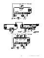
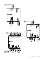
Wiring diagrams . . . . . 34
Wiring diagram for multiple units - IR32 panel mounting connections . . . 34
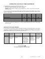
Operating states of the equipment . . . . 38
Sequence of main phases . . . . . 38
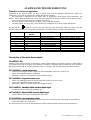
Alarms and troubleshooting . . . . . 39
What to do if the IR32S, IRDRSE/S0 fails to work . . . . 41
What to do if the IR32Y fails to work . . . . 41
What to do if the IR32P or IR32C, IRDRC fails to work . . . 43
Technical characteristics . . . . . 44
Temperature/resistance ratios for NTC thermistors. . . . 48
IR32 dimensions . . . . . 50
Code numbers for ordering controls and accessories . . . 51
IR96: microprocessor-based freezer controller . . . . 53
New functions . . . . . 53
Technical features -- Connections . . . . 55
Ir96: keys functioning . . . . . 56
Functioning . . . . . 56
IR96: parameters . . . . . 58
Parameters modification . . . . . 58
New-set values memorisation . . . . . 58
List of parameters . . . . . 59
Description of particular parameters and performances . . . 61
Memorisation of minimum/maximum temperature . . . . 61
Functioning of the relay 4 . . . . . 61
Type of sensor - Digital Inputs Configuration . . . . 61
IR96: alarms . . . . . 62
Dimensions . . . . . 62

Cod. +030220151 - Rel. 2.1 - 04/09/98
1
GENERAL FEATURES
Models available
The electronic controllers of the Infrared series have been specifically designed for the control and regulation
of refrigeration units. These new instruments are microprocessor based and come complete with a LED
display. Carel offers a wide range of models to ensure that the exact instrument is available for your
application at the most competitive price. In brief, here is a list of the main models available:
IR32M
An electronic digital thermometer, capable of displaying the temperature from one or two
sensors. It is the ideal solution for applications requiring temperature display. It is possible to
display the temperature of either the first sensor or the second one alternatively by simply
connecting a switch to the thermometer. Additionally, the modification of a specific parameter
will allow you to get the weighted average of the two sensors. For further information see the
parameter '/4' (virtual sensor).
IR32S
IRDRSE
IRDRS0
The ideal solution for regulation of 'static' refrigeration units (without evaporator fans) working
at normal temperature ranges (above 0ºC). IR32S works both as a thermometer − it displays
the temperature − and as an electronic thermostat: it activates the compressor (or the
solenoid valve in piped systems) to keep the temperature at the set value. You can select the
time-interval between successive defrosting cycles as well as their duration. IR32S can be
used simply as a thermostat. In this case it proves to be extremely useful in cooling or
heating applications where it activates compressors, heaters, etc. IR32S, in fact, can work
either in the 'Direct' (Cooling) or 'Reverse' (Heating) functioning mode, by simply selecting the
dedicated parameter (see 'r3' below) or acting on the digital input. The operating temperature
range is 40/90ºC (-40 /130 ºC with PTC sensor).
IR32Y
Specifically designed for the control and regulation of 'static' refrigeration units working at low
temperature ranges (below 0ºC), requiring 'active' defrost (that is, electrical or hot gas
defrost). IR32Y, in fact, works not only as a thermometer and a thermostat at the same time,
but it also controls defrost. You can select the time-interval between successive defrost cycles
as well as their duration. Defrosting will be stopped when the defrost end temperature is
reached (it is necessary to connect a defrost sensor to the evaporator). A timed fail safe is
included as standard in the event that the defrost end temperature is not reached. A parameter will
allow you to select the defrost end mode most suitable to your application, i.e.
time/temperature or time/time.
IR32P
Specifically designed for the control and regulation of ventilated refrigeration units (with
evaporator fan) working at low temperatures. It features the same functions described above
for IR32Y plus control of the evaporator fans, thus optimizing their ON/OFF routines in
relation to the specific characteristics of your unit. IR32P has no relays; therefore it is
necessary to add a power card, either the S90RDPW200 or the S90OEM4PWR. The first card
has 3 relays for the control of compressor, fan and defrosting. The compressor relay can
control units up to 1 Hp at 240Vac. The second card has 4 relays; it allows you to enjoy the
benefits of the 'Multifunction output' to operate an auxiliary output (cold room light, de-misting
fan, etc.) or to send a remote alarm signal. Both cards can be powered with either 24 Vac or
240Vac.
IR32C
IRDRC
It is a complete solution for the control and the management of ventilated units working at low
temperatures. It performs all the functions of the IR32P model complete with the
S90OEM4PWR card, with everything packed into one case. Thanks to the very latest
technology, we have achieved a unique product that integrates the 4 relays (2000 VA) into a
case just 74mm wide, 72mm deep and 33mm height, without sacrificing performance and
reliability.
IR96
Ir96 is a microprocessor based controller designed for the management of freezer with gravity
or forced-air evaporators. It has 5 relay outputs available to control all the main actuators:
compressor (directly up to 1Hp single-phase), evaporator fans and defrosting. The fourth relay
allows remote signalling of any malfunctioning (high temperature, faulty sensors,...). The fifth
relay can be used to control the unit lights or other auxiliary functions. Two programmable
digital inputs allow innovative performances: automatic alarm management, real time
defrosting, management of lights subjected to the door switch.

Cod. +030220151 - Rel. 2.1 - 04/09/98
2
Main features of the Infrared series
Power supply
All the instruments of the Infrared series − except IR32P − come complete with WIDE RANGE power
supply, allowing you to power your units with either direct or alternating current, from 12 to 24Volt. The 'S'
model is also available with a UNIVERSAL or a HIGH range power supply that allow to extend the power
supply range: from 24 to 240V or from 110 to 240V respectively. All Infrared instruments fit automatically to
the voltage supplied.
With the UNIVERSAL and HIGH range power supply any external transformer to change from 24Vac to
240Vac or from 110 to 240V is not required. Such features simplify your work and provide the maximum
reliability as the controller is capable of adjusting perfectly any fluctuation of supply
IR32P is powered by means of the power card and can be supplied either with 24Vac or 240Vac.
Soft touch keypad
It is made of silicone for both functional reasons (especially when pressing the keys) and aesthetic reasons
(it matches the new lines and structures of the latest refrigeration units). The Infrared series is the result of
specific ergonomic choices designed to simplify all procedures. Setting or modifying a parameter, for
example, now requires the touch of just one button.
LED Display
The LED display shows two and half digits' ranging from -40 to +90ºC (-40/+130 with PTC sensor); the
temperature value appears with one decimal point (you can omit it by acting on the dedicated parameter)
ranging from -19.9 to +19.9. In addition there are up to 4 LED indicators (depending on the model) that light
up when the output they represent is ON. They will flash in case of external problems relative to the output
(see Multifunction input) or during active/current procedures.
Buzzer
All controllers come complete with an alarm buzzer upon request.
Remote control
To make it easier to set and display the working parameters, you can request your controller complete with
the Infrared receiver. In this case you will be able to use the remote control unit to perform any operation.
One remote control unit can be used for several IR32 instruments placed within the same room, with no
interference since each controller can be identified by a specific access code.
Duty setting
A completely new function allows the compressor to run even if the regulation sensor is damaged. In case of
short-circuit or open-circuit sensor, the compressor is instructed to start on the basis of time-intervals
(minutes) selected through the 'duty setting' parameter ('c4') and to turn OFF every 15 minutes (fixed time-
interval).
Multifunction input
The Infrared instruments come complete with a digital input that can be used in different ways, depending on
the value given to the parameter 'A4'. The multifunction input can be used to enable/disable defrost, to act
on serious alarm conditions requiring either the immediate (for example, high pressure alarms) or delayed
lockout of the unit (low pressure alarms).
Multifunction output
Some models come complete with a fourth relay for the remote alarm signal or to drive auxiliary ON/OFF
devices.
Keypad protection
The keypad and/or the remote control unit can be deactivated to prevent unauthorized personnel from
modifying settings (especially when the controller is located in a public area).
Continuous cycle
This function operates the ON routines of the compressor for a 't' time selected through a dedicated
parameter. This is particularly useful when a rapid fall of temperature is required.

Cod. +030220151 - Rel. 2.1 - 04/09/98
3
Serial connection
All instruments can be equipped with a 'serial' card that can be fitted any time, even after the controller has
been installed. The serial output allows you to connect the controller to a supervisory and/or telamintenance
system.
In addition, Carel has developed 'MODÌ, a special program for the trouble-free configuration of the Infrared
instruments via Personal Computer through a serial output. 'Modì’ proves to be extremely useful especially
when you need to configure several controllers.
Virtual sensor
All models equipped with two sensors (all except IR32S) may be adjusted to regulate the unit on the basis of
the weighted average temperature or the two sensors. It is also possible to choose which sensor − either the
first or the second one − will be the most important one for the determination of the final value. The value
relative to the virtual sensor will appear on the display (see parameter '/4').
Dimensions
Even the most sophisticated model has standard dimensions. Panel mountings usually require a 71x29mm
drilling template thus making it extremely simple and fast to replace older controllers with new Infrared
instruments.
Protection index
The O-RING inside the front panel of the instrument and the material of the keypad ensure a very high
protection index (IP65). All controllers come complete with a flat gasket that contributes to increase the
protection index of the panel housing the controller.
Fastening the controller
Fastening the controller is achieved using a small clamp made of plastic. No screws are required.
Test-in-circuit
The instruments of the Infrared series are the result of the most advanced SMD technology. All controllers
are built using high quality components. Quality control includes a rigorous 'TEST-IN-CIRCUIT' on each
single component to ensure that your controller is entirely reliable.
NTC sensor
The Infrared instruments have been designed to be connected to Carel NTC sensors since they give greater
precision than different sensor models. However, special versions capable of receiving the most common
types of PTC sensors are available upon request.
Watch dog
It is a special device that will protect the microprocessor of the controller even in the event of strong
electromagnetic noises. In case of abnormal conditions the watch dog restores the initial functioning status of
your unit. Only Carel controllers come complete with this exclusive safety device.
Immunity against noise
The INFRARED series complies with the EEC standards regarding the electromagnetic compatibility.
& ISO9001 Approvals
Quality and safety of the INFRARED series are assured by the ISO 9001 design and production certificate as
well as the CE labelling.

Cod. +030220151 - Rel. 2.1 - 04/09/98
4
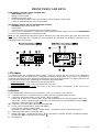
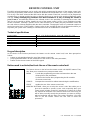
FRONT PANEL AND KEYS
Each Infrared controller comes complete with:
• Wide Range power supply
• display 2 and 1/2 digits
• temperature decimal point
• LEDs indicating the outputs status (the number of LEDs depends on the model)
• 4 keys for programming the unit (except IR32M);
The following options are also available upon request:
• Universal power supply (IR32S only)
• alarm buzzer
• infrared receiver for programming the unit via remote control
• serial card for connection to a supervisory and/or telemaintenance system such as Carel MasterPlant
for the control and regulation of refrigeration units.
Note: you are requested to indicate the optional functions you need when placing the order. Only the serial
card can be fitted after the controller has been installed. The IRDRSE and IR32SOU versions are not
equipped with the serial output.
LED display
The display shows the temperature values (range: -40/90 or -40/+130 with PTC sensor). The temperature
measured by the sensor is displayed to a 10th degree resolution ranging from -19.9 to +19.9. It is possible to
exclude the decimal part of the degree by modifying the value of the /6 parameter. The display will show one
of the following values/codes, depending on the function being performed.
• normal functioning: value measured by the ambient sensor;
• parameter selection stage: code of the parameter or its value;
• when an alarm condition occurs: the code of the alarm flashes alternatively to the value of the
temperature.
Indicators
On the display there are some luminous indicators (see ƒ to ˆ above). They indicate:
3 current transmission via remote unit (the controller must be equipped with IR receiver);
4 compressor ON routine (IR32S, IR32Y, IR32C, IR32P e IRDRC);
if the IR32S as been set to work as the ‘T’ model (see parameter H1=0), this LED indicates the status
(ON or OFF), of the controlled output (compressor or other devices); in the IRDRSE/S0 models comp
indication is replaced with the symbol
4b continuous cycle ON routine (all models except IR32M)
5 fan ON routine (models IR32C, IR32P and IRDRC);
second sensor reading (model IR32M);
REVERSE function mode (heating) - models IR32S - configured to work as thermostats (H1=0)
6 fourth relay active (IR32C and IR32P only)
7 defrost ON routine - models IR32S, IR32Y, IR32C and IR32P; in IRDRS, IRDRSE and IRDRS0 models
the indication def is replaced with the symbol
8 decimal point

Cod. +030220151 - Rel. 2.1 - 04/09/98
5
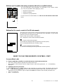
Keypad
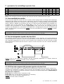
The buttons on the front panel of the instrument allow you to perform the following functions:
• - goes to the next parameter;
- increases the value of the parameter;
if pressed simultaneously to the button no. 10 (*):
- activates/deactivates the continuous cycle;
in models IR32C and IR32P complete with S90OEM4PWR:
- activates/deactivates the auxiliary output
‚ - silences the buzzer (if present);
if pressed for more than 5 seconds:
- allows you to enter the 'F' parameters section (Frequent);
if pressed for more than 5 seconds together with the button no. 9:
- allows you to enter the 'C' parameters section (Configuration);
if pressed when turning ON the instrument:
- activates the RESET procedure
‰ displays and/or selects the SET-POINT;
- displays the value of the selected parameter;
if pressed for more than 5 seconds together with the button no. 2:
- allows you to enter type 'C' parameters (Configuration);
Š
- goes to the previous parameter;
- decreases the value of the parameter;
if pressed for more than 5 seconds:
- activates a manual defrosting cycle (except version IR32S with parameter H1=0);
if pressed together with the button no. 1 (*):
- activates/deactivates the continuous cycle.
(*) Warning: in order to activate a continuous cycle, press the button no. 10 first and then the button no. 1.

Cod. +030220151 - Rel. 2.1 - 04/09/98
6
INSTALLATION
Standard configuration
All Infrared controllers are supplied ready to use. The values of the main working parameters have been
factory-set on the basis of the most frequent and common requirements to meet the greatest number of
application needs. It is always possible to change the preset values to personalize the unit according to your
requirements. The notes below show the default values as well as the parameters that can be modified in
relation to the type of refrigeration unit to be controlled (set-point, differential, etc.). We will also list all the
parameters whose values should always be carefully checked before starting the unit.
The factory-set program makes your unit perform the following main functions:
IR32M: specifically programmed for the detection of two different temperature values. Connect a switch to
the digital input to switch from the first to the second sensor. IR32M can be connected to either NTC or PTC
sensors, as specified when placing the order.
IR32S, IRDRSE and IRDRS0: configured as a thermostat with DIRECT functioning mode (to control
cooling), set-point = 0 ºC and differential= 2 ºC. The default values also include a high temperature alarm set
at 10 ºC above the set-point and a low temperature alarm set at -10 ºC below the set-point. Should you
change the default set-point (0 ºC), the deviation values relative to the alarms will remain +/-10 degrees
above and below the new set-point. When the continuous cycle functioning mode is ON, it will last 4 hours.
After this cycle the temperature alarm will be delayed for two hours.
IR32Y: features the same functions as IR32S. In addition, it is programmed to control timed electric defrost
(duration = 30 minutes) and 8-hour intervals between successive defrost cycles. The temperature displayed
during the defrost cycle will be that acquired before the beginning of the cycle. At the end of the defrost cycle
the evaporator will drain down for 2 minutes and the high temperature alarm will be inhibited for 1 hour.
IR32P: performs the same functions as IR32Y plus the control and regulation of the evaporator fans, these
will be stopped when the compressor is off and during each defrost cycle. At the end of the drain-down time,
the fans will remain off for 3 minutes; this time-delay is necessary to restore the normal temperature of the
evaporator before re-starting the fans. In the IR32P models the defrost cycle will be interrupted as soon as
the evaporator sensor measures a temperature corresponding to 4ºC (defrost based on temperature). The
defrost cycle, however, will last max. 30 minutes. If your controller is complete with the S90OEM4PWR
card, the fourth relay will change state thus indicating an alarm condition.
IR32C, IRDRC: has the same configuration as IR32P plus the 4-relay card. For IR96, please see on page 36.
The following operations should be perform to ensure trouble-free operation of the Infrared unit:
1) installation;
2) connection to sensors, power supply and output contactors;
3) working parameters selection.
Installation
1) insert the instrument into the previously adjusted hole.
2) fasten the instrument to the panel by means of the dedicated clamp.
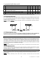
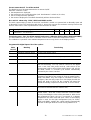
Connection
1) carry out all electrical connections following the instructions given in this guide (see “Caution”at the end
of this chapter);
2) connect the sensors following the installation instructions carefully.
NOTE: all IR32 and IRDR instruments have been designed for NTC sensors. However, should your system
comprise PTC sensors, ask for a PTC model when placing the order (it is available only for panel mounting
IR32).

Cod. +030220151 - Rel. 2.1 - 04/09/98
7
Cautions
Warning: Before making any electrical installation read the instructions and take careful note of the
diagrams on the following pages. Remember that all safety devices necessary to correct operation must be
fitted in advance.
Installation should be avoided in the following circumstances:
1. Relative humidity greater than 85%.
2. Heavy vibration or shocks.
3. Exposure to continuous water sprays.
4. Exposure to corrosive or pollutant gases (e.g. sulphurous or ammoniacal fumes, saline mist, smoke) so
as to avoid corrosion and oxidisation.
5. Strong magnetic and/or radio interference (therefore installation of the equipment near transmitter aerials
should be avoided).
6. Exposure of controls to direct solar radiation and other climatic influences.
The following must be observed when connecting the controllers:
1. Connecting a power supply of the incorrect voltage can seriously damage the system.
2. Use the correct type of connectors. Slacken each screw, insert the lead and then tighten the screws.
Finally, tug gently to make sure there is a secure grip.
3. So as to avoid any possible electro-magnetic interference, separate as far as possible the signal leads
from the sensors, and the digital inputs from the induction and power leads. Do not place power leads
and sensor leads in the same channels. Furthermore, avoid placing sensor leads in the immediate
vicinity of powered components (thermo-magnetic contacts or others).
Keep the sensor leads as short as possible and avoid their sharing routes with power leads. As defrost
sensors use only guaranteed IP67 sensors; place the sensors with the bulb upright in a position to assist
drainage of any condensation which may occur. Note that thermistor temperature sensors (NTC or PTC)
have no polarity and the terminals may therefore be connected either way.
4. Sensors can be located at distances of up to a maximum of 100 meters from the control. To connect
sensors, leads with a minimum cross-section of 1 square millimetre should be used, and may be
screened. In this case the screening should be connected to terminal 7 on the control; it should not be
connected to earth or to any fitting at the other end of the screening (i.e. the end nearer to the sensor).
5. Whatever may be provided for through the IR32SER board, it is necessary to take care when earthing the
system. In particular:
a) the secondary side of transformers supplying the equipment must not be earthed. If it should be
necessary to connect to a transformer which has a secondary earth, an insulating transformer must be
interposed. If necessary, Carel has available an insulating transformer with the following characteristics:
24Vac to 24Vac, 20VA, reference no. 0907651AXX.
b) if several controls are connected to the same transformer, care must be taken with polarity when
wiring: terminals "4" of all controls must all be connected to the same terminal on the transformer;
terminals "5" of the controls must all be connected to the other transformer terminal. See diagram for
further details.
6. Avoid touching with the fingers the electronic components mounted on the boards, so as to avoid
electrostatic discharges from the operator to the components, as these could become seriously damaged.

Cod. +030220151 - Rel. 2.1 - 04/09/98
8
Selection of the main working parameters
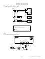
Setting the main working parameters - Ambient set-point
The factory set-point is 0ºC. Should you need a different value, more suitable to your specific application
requirements, observe the following instructions:
• press
for 1 second: the set-point value will appear on the display;
• after a while, the value will begin to flash;
• increase or decrease the set-point using the and/or keys until you reach the requested
value;
• press
again to confirm the new value;
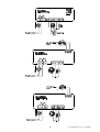
Setting the differential (hysteresis of the regulator)
The factory-set differential is 2ºC. Should you need a different value, more suitable to your specific
application requirements, operate as follows:
• press for more than 5 seconds (in case of active alarm, silence the buzzer first);
• the code of the first modifiable parameter (/C) appears on the display;
• press either or
until the code 'rd' appears;
• press to display the relative value;
• increase or decrease the value using either the or buttons until you reach the requested
value;
• press again to confirm temporarily the new value and display the code of the parameter;
• press to memorize the new value and exit the procedure.
Other important parameters
For all the models:
As indicated above, all Infrared instruments have been programmed to detect both the high and the low
temperature alarm. In the event of abnormal conditions the internal buzzer (if present) will sound and the
display will show the code of the alarm, that is 'HI' for high temperature, 'LO' for low temperature.
High/Low temperature alarms are generated by abnormal temperature conditions:
• high temperature alarm: the temperature measured by the ambient sensor is 'AH' degrees (or more)
above the set-point: ambient temperature > set-point + AH;
• low temperature alarm: the temperature measured by the ambient sensor is 'AL' degrees (or more)
below the set-point: ambient temperature < set point - AL.
On the basis of the default values, AL = 10 and AH = 10.
In the event of a temperature alarm, the relative message will be delayed for 120 minutes (Ad = 120). After
that the 'HI' or 'LO' alarm will be generated. No alarms will be generated if normal temperature conditions are
restored within the Ad time-interval (the temperature should range within +/-10 degrees of the selected set
point).
While installing the unit, the temperature might take more than 120 minutes (Ad time) to range between the
set limits. Consequently the temperature alarm will be generated. In order to avoid this problem, we suggest
- during this stage only - increasing the Ad time-interval, by increasing the value of the Ad parameter.

Cod. +030220151 - Rel. 2.1 - 04/09/98
9
Models IR32S, IRDRS, IRDRSE and IR32Y
Configuration of the 'type' of instrument
The INFRARED series comprises two models - IR32S and IR32Y - with different operating modes. Both
models feature the H1 parameter (see below) allowing you to select one of the two operating modes. IR32S,
IRDRS and IRDRSE can operate either as a simple thermostat (H1=0, default value) or as a thermostat and
defrost controller for static units operaring at normal temperatures (the defrost cycle starts when the
compressor stops, H1=1). For the second type of operating logic, it is necessary to configure the instrument
and give H1 the value '1' (H1=1, see below 'How to modify the working parameters').
IR32Y controls and regulates both temperature and defrost for static units working at low temperature
ranges. The defrost cycle can use the timed ('X' functioning mode) or temperature end (evaporator
temperature, 'Y' functioning mode). In the second case the instrument requires another sensor - called the
defrost end sensor - to be placed on the evaporator (when in the 'X' functioning mode, the input for the
'defrost end sensor' remains free). The 'H1' parameter allows you to select either the 'X' or 'Y' functioning
logic. When H1=0 (default value), the instrument works in the 'X' logic (end of defrost based on time). If you
want the end of defrost based on temperature, select the 'Y' logic, that is H1=1 (see below 'How to modify the
working parameters').
Defrost parameters
When using the Infrared unit to control defrost, check the following parameters before starting the unit:
Models IR32S, IRDRS and IRDRSE (with H1=1), IR32Y, IR32C, IRDRC and IR32P:
dI: Time-interval between defrost cycles: defrost cycles occur periodically, depending on the time-
intervals (hours) set through the 'dl' parameter. When the time-interval is 0 (dl=0), the defrosting cycle is
never carried out unless it is forced via keypad (manual defrost) or via the digital input (see A4 parameter).
Temperature alarms are inhibited during each defrost. Def.: 8 (hours)
dP: Maximum defrost time: the dP parameter determines the maximum duration of the defrosting cycle
(minutes). In the models without evaporator fan (IR32S with H1=1 and IR32Y with H1=0) this parameter
indicates the actual duration of the defrost. Def.: 30 minutes
Models IR32Y, IR32C, IRDRC and IR32P
d0: Type of defrost: in the models equipped with defrost relay (IR32Y, IR32C and IR32P) 'dO' determines the
type of defrost, that is: 0 = electrical defrosting, 1 = hot gas defrosting. Def.: d0=0, electrical defrosting
dt: Defrosting end SET-POINT: in the models equipped with defrost end sensor (IR32Y with H1=1,
IR32C, IRDRC and IR32P) 'dt' allows you to set the defrost end temperature. Remember, however, that the
maximum duration of the defrost cycle corresponds to the value (in minutes) given to the dP parameter.
When the temperature measured by the defrost end sensor is higher than the defrost end set point set by the
User, the defrost cycle will be omitted. Def.: 4 ºC
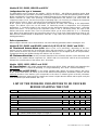
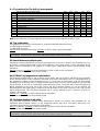
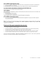
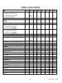
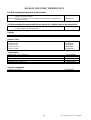
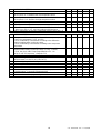
LIST OF THE WORKING PARAMETERS TO BE CHECKED
BEFORE STARTING THE UNIT
Code Parameter Type Min Max M.u. Def
PARAMETERS OF THE REGULATOR
rd Control differential F 0.1 +19.9 °C/°F 2
DEFROST PARAMETERS
d0 Type of defrost (0=electrical, 1=hot gas) C 0 1 flag 0
dI Time-intervals between def. cycles F 0 199 hours 8
dt Defrost end set-point F -40 +199 °C/°F 4
ALARM PARAMETERS
Ad Temperature alarm delay F 0 +199 min 120
OTHERS FUNCTIONS
H1 Model [IR32Y: 0=type X; 1=type Y]
[IR32S, IRDRSE/S0: 0=type T; 1=type S]
C 0 1 flag 0

Cod. +030220151 - Rel. 2.1 - 04/09/98
10
HOW TO MODIFY THE WORKING PARAMETERS
The microprocessor of the INFRARED instruments allows you to configure the functions of your controller
according to the application requirements. To simplify this operation, we have divided the Working
Parameters into two main groups:
• frequently used parameters (indicated as 'F' parameters in the tables below);
• configuration parameters ('C'), protected by a code or password to prevent unauthorised access to the
data.
All parameters can be modified via keypad (except IR32M, with no keys) as well as via remote control unit or
serial line. In order to modify the parameters via front panel keypad, observe the following instructions:
Gaining access
To gain access to the 'F' parameters:
• press the
for more than 5 seconds (in case of alarm condition, silence the buzzer first);
• the display shows the code of the first modifiable parameter (/C);
To gain access to the 'C' parameters:
• press the
and
buttons simultaneously for more than 5 seconds;
• the display shows 00;
• press either the or button until '22' (the password) appears;
• confirm pressing ;
• the display shows the code of the first modifiable parameter, that is '/C'.
How to modify the parameters
Modifying parameters: after having displayed the first parameter, either 'C' or 'F', follow these instructions:
• press either or until you reach the parameter whose value needs to be changed;
• press
to display its current value;
• increase of decrease its value using the or key until you reach the requested value;
• press
to memorize temporarily the new value and display the code of the parameter again;
• press again either or to go to the next parameter you want to change;
then repeat the operations as indicated above, starting from "press .."
How to exit the procedure
How to memorize the new set values
• Press
to memorize the new values and exit the procedure.
Important: it is necessary to press
to memorize the new values. In case of power failure before
has been pressed, all modifications will be lost. Whenever you modify the value of a parameter, we strongly
recommend writing it down in the dedicated column situated on page 46 of this guide (see column 'New value').
How to exit the procedure without memorizing the modified data
• do not press any key for at least 60 seconds (TIME OUT). The instrument will return to its normal
functioning mode.

Cod. +030220151 - Rel. 2.1 - 04/09/98
11
RESET PROCEDURE
In case of abnormal conditions - strong electromagnetic noises, for example - there might be errors when
storing data. Consequently the unit might not work correctly. When the microprocessor identifies an error in
the process of storing data, one of the following groups of letters will be displayed:
EA, EB or EE
In order to restore normal working conditions, it is necessary to RESET the instrument (for the instruments
having serial number < 5,000 see the note at the end of this guide). Please note that RESETTING the
instrument is quite an unusual procedure, as well as the causes that can make it necessary. We would also
like to point out that competitive controllers are not capable of dealing with such serious conditions which
would normally lead to inevitable damages to the instrument. This is the reason why Carel have
implemented the RESET function in all the controllers of the INFRARED series, thus providing safer and
more reliable instruments, always capable of restoring their normal functions without any problem. Should
this error message appear without any apparent reason, we strongly recommend inspecting the unit carefully
and finding out the causes that generated it. (Please also find useful information at the end of the
“Installation” chapter);
To reset the controller:
•• turn off the instrument;
• press and, keeping it pressed, turn on the controller;
• the display shows "_c_";
• after a few seconds, the instrument automatically allows you to gain access to the 'C' parameters where
you can modify the default values according to your specific requirements. Also the /0 parameter will be
displayed thus allowing you to select the type of sensor you want to use (NTC or PTC):
Important: after the RESET procedure the values of each single parameter will be exactly the
factory-set ones (default values). Any modification made before the reset procedure will therefore
be lost.
If you are using an instrument set to receive a PTC sensor, it is necessary to set the parameter /0=1
because the default value appearing after the reset procedure will be 0 (/0=0, NTC sensor).
For further information see the parameters relative to the sensors.
• if your instrument requires default values, normal working conditions will be restored by simply
pressing
.
• if the instrument requires a different configuration, it is necessary to modify all parameters whose values
are different from the factory-settings.
After having modified the parameters, press to exit the procedure and come back to the normal working
mode.
Note: the reset procedure should be carried out by expert personnel only. We would like to point out,
however, that such a procedure does not damage the instrument but it simply restores its factory-set
configuration. As a result, you can resort to this in the event of confused or incorrect modification of the
working parameters. In this case, in fact, resetting the controller will allow you to recover the factory-set
configuration and restart the modification procedure, without any problem.
Should 'EE' persist, even after the above procedure has been carried out, press until the message
disappears. If you do not manage to clear the EE error, it will be necessary to replace the controller. If the
EE message occurs frequently or disappears with difficulty, it is better to get in contact with the nearest
service centre to check the precision of the instrument.

Cod. +030220151 - Rel. 2.1 - 04/09/98
12
REMOTE CONTROL UNIT
The IR32 Infrared instruments can be easily and quickly programmed by means of the remote control unit.
Until now programming multi-function instruments dedicated to refrigeration was a very complex procedure.
This is why Carel have enhanced the IR32 series with the remote control unit, used not only to program the
controller from a remote position but also to allow the End-User to set the main working parameters easily
and fast. Today, modifying any parameter of an IR32 instrument is as easy as turning the volume of
your TV 55or 66.. An interesting feature of the Infrared series is the possibility of selecting the access code
(H3) for each controller to further simplify the use of the remote control. In fact, if your installation includes
several controllers, selecting a specific access code will allow you to modify only the parameters of the unit
the code refers to, without interfering with the other controllers. Changing the value of a parameter requires a
special procedure (see 'START' button). Further safety is also provided by the 'H2' parameter that allows you
to protect your system from unwilling or unauthorised access or modification of all set data.
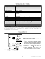
Technical specifications
Power supply no.2 1.5V alkaline batteries (type UM-4 AAA, IEC R03)
Case plastic
Dimensions 60x160x18mm
Storage -25/+70°C
Operating temperature 0/50°C
Transmission Infrared
Weight 80g (without batteries)
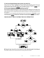
Keypad description
On the basis of the function performed, the buttons on the remote control unit, have been grouped as
follows:
• buttons to activate/deactivate the use of the remote control unit;
• pre-programmed buttons for the modification of the values of the main parameters;
• buttons for the remote control of the IR32 keypad.
Buttons used to activate/deactivate the use of the remote control unit
The buttons shown on the left are the remote control unit ON/OFF buttons. They
also allow you to memorize any new parameter value.
MEMO 1) ends the programming procedure and memorizes the new
values given to the parameters;
2) silences the buzzer when programming the IR controller
via remote control unit;
CANCEL interrupts the transmission without memorizing the modifications;
START enables the use of the remote control unit;
NUMERIC BUTTONS: allow you to select the access code. We advise you to
give each controller a specific access code, especially when your
control panel includes several IR instruments or when all of them
are exposed to the beam of the remote control unit. In this way you
will be able to modify exactly the parameters you want to change,
without interfering with the data of the other controllers. (See also
'How to use the remote control unit' and 'How to select the
password').

Cod. +030220151 - Rel. 2.1 - 04/09/98
13
Buttons used to modify the main parameters (directly accessible buttons)
The most frequently used parameters are indicated on the remote control
unit. They are grouped in three light-grey zones:
• temperature parameters;
• defrost parameters;
• continuous cycle parameters.
For the correct use of the buttons see 'How to use the remote control unit'
below.
Buttons for the remote control of the IR instruments
The green zone of the remote control unit reproduces exactly the keypad of the
IR instruments and allows you to perform the same operations, as you would
perform if you were using the keypad.
Here are the main functions of the buttons:
SEL displays the value of the selected parameter;
1) goes to the next parameter;
2) increases the displayed data (parameters selection phase);
AUX activates/deactivates the auxiliary output;
1) goes to the previous parameter;
2) decreases the displayed value (parameters selection phase).
HOW TO USE THE REMOTE CONTROL UNIT
Access without code
1) How to enable the controller to receive the remote control unit transmission
• press the 'START' button to operate the remote control unit;
• the controller's LED indicator above the digits flashes and the first parameter - '/C' - is immediately
displayed.
2) Modifying the main parameters
• press either the + or - button relative to the parameter you want to modify. The display will show the
code of the selected parameter (see the codes of the parameters listed in the Instruction Sheet of the
instrument). Press the button again to display the value associated to the selected parameter and
• press + to increase it;
• press - to decrease it.

Cod. +030220151 - Rel. 2.1 - 04/09/98
14
The section including directly accessible buttons also comprises 3 buttons that activate/deactivate the
function they represent:
DEFROST SECTION:
START activates/deactivates a manual defrost cycle;
°C evap. displays the temperature value measured by the defrost end sensor (if present) or the
value measured by the second sensor (IR32M model).
Important: this function is always active. Consequently the temperature measured by the second sensor will
be always displayed without having to press the 'START' button or select the access code (see point 5
below).
CONTINUOUS CYCLE SECTION:
C.cont. activates a continuous cycle;
• to exit the programming procedure see point 4 below.
3) How to modify the parameters not directly indicated by a specific button
The other parameters - not directly associated to a specific button on the remote control unit - can be easily
modified as follows:
• perform the same operations described in point 1 above until the first parameter '/C' appears on the
display;
3.1)
• press either or
until the display shows the parameter you want to modify;
• press SEL to display the value of the selected parameter;
• press either or to increase/decrease its value;
• press SEL to confirm temporarily the new value and display again the code of the parameter;
• to modify another parameter repeat the operations described above starting from point 3.1;
• exit the programming procedure as described in point 4 below.
4) How to exit the programming procedure
• press PRG to exit and memorize all modifications;
• press CANCEL to exit without memorizing the previous modifications;
• do not press any button for at least 60 seconds (TIME OUT).
In this way the previous modifications will be cancelled.
Access with code
5) How to enable the controller to receive the remote control unit transmission
• press 'START' to operate the remote control unit;
• all the controllers exposed to the beam of the remote control unit will display their own access code;
• select the access code of the controller whose parameter you intend to modify using the numeric section
on the remote control unit. Select the code correctly (if the code of the controller is 05, press 0 and 5).
• the controller's LED indicator above the digits flashes and, simultaneously, the code of the first
parameter '/C' appears on the display.
• perform the same operations described in point 2) or 3) above.
How to select the access code
Setting the access code
All IR32 controllers have no factory-set access codes. The User can choose and set his own access
codes by simply modifying the H3 parameter as follows:
• press 'START' to operate the remote control unit;
• the controller's LED indicator above the digits flashes and the first parameter ('/C) appears immediately.
• press to display the H3 parameter;
• press SEL to display its value (default 00);
• press to select the requested value (from 01 to 199);
• press SEL to confirm the new value and display again the H3 code;
• press MEMO to memorize the access code and exit the procedure.
Removing the code
• repeat the operations described above and give the H3 parameter the value 00 (H3=00). In this way you
can program your controller/s without selecting the access code.

Cod. +030220151 - Rel. 2.1 - 04/09/98
15
FURTHER INFORMATION
Configuration parameters
As already mentioned, (see chapter 'How to change the operating parameters'), there are two types of
parameter:
• parameters used frequently (indicated by 'F' in the following tables)
• configuration parameters (type C) which are protected by a password to prevent unwanted modification.
Categorisation of parameters
Besides being divided into TYPES, the parameters are grouped into logical categories labelled by letters
indicating their function. The categories and their identifying letters are given below:
Category Description
Flashing 00 Does not indicate a category, but merely that the password must be
entered in order to gain access to the configuration parameters.
/ parameters relative to the temperature sensor
r parameters relative to the temperature regulation
C parameters relative to the compressor management
d parameters relative to the defrost management
A parameters relative to the alarm management
F parameters relative to the evaporator fan management
H general parameter configuration
NEW RELEASE
The instruments with serial number greater than 100,000 have a new software release − compatible with the
previous one − offering new functionalities described in detail in the following chapter.
The password
Flashing 00: PASSWORD
This is a protective device which intentionally "complicates" access to Configuration parameters in order to
prevent accidental changes or any that might be made by unauthorised persons. Type C parameters are in
fact those which alter the control configuration. Once the configuration parameters have been entered by use
of the password, the system allows the user to alter type F parameters as requested.
The password request (flashing 00) appears when the two buttons and are pressed at the same
time. Access to type C parameters is gained as follows:
• press or to produce 22 or the correct password;
• confirm with ;
• the code of the first modifiable parameter is displayed, that is '/C'. (On controls with serial number
less than 5,000, '/O' is displayed instead of '/C' . See the relative note on page 49).
In the following paragraphs all the parameters will be described, indicating in which versions they are
available and what values can be assigned to them. (Remember that on version IR32M the parameters are
modifiable only through the remote controller and the serial input).
There will also be indicated the default value (Def.), which is the value given to the parameter in the factory.
Furthermore it will be stated whether the parameter is modifiable through the remote controller with "direct
access", that is, whether there is a specific button for modifying it on the remote controller. It should be
remembered that ALL the parameters are modifiable through the remote controller; the 16 most frequent
parameters can however be modified directly by means of a dedicated button ("direct access").

Cod. +030220151 - Rel. 2.1 - 04/09/98
16
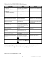
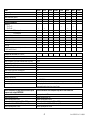
/ = Parameters for the management of the temperature sensors
SENSOR PARAMETERS Type Min. Max. Unit Def
/0 Type of sensor (0=NTC, 1=PTC) C 0 1 - 0
/C Calibration F -20 +20 +C/+F 0.0
/2 Stability measurement C 1 15 - 4
/3 Sensor reading speed C 1 15 - 8
/4 Virtual sensor C 0 100 0
/5
°C / °F (0=°C,1=°F)
C 0 1 flag 0
/6 Decimal point (0=yes, 1=no) C 0 1 flag 0
Note: for the set times to become operative, the instrument must be switched off and on again.
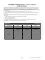
Short descriptive note about sensors with thermistors types NTC and PTC:
Equipment of the IR32 series is designed to work with NTC Carel temperature sensors, or sensors using
thermistors with a negative characteristic (NTC stands for Negative Temperature Coefficient). This type of
thermistor modifies an electrical parameter (its own resistance) in inverse proportion to any change in
temperature; that is, the resistance falls as the temperature rises, and vice versa. Other types of thermistor
are on the market. Widely available are PTC thermistors with a resistance of 985 Ohms at 25°C. PTC stands
for Positive Temperature Coefficient; by contrast with the NTC, these increase their resistance directly
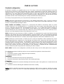
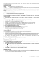
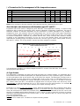
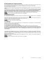
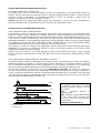
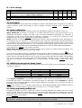
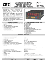
according to the temperature increasing. As you can see in the diagram below, (the horizontal axis
represents the operating range, the vertical axis the error), the NTC type of sensor shows greater accuracy
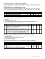
than the PTC version. This is why the NTC sensors have been adopted as standard.
Maximun variation shown by types NTC and PTC temperature probes in
relation to intended theoretical values .
-4
-3
-2
-1
0
1
2
3
-30 -25 -20 -15 -10 -5 0 5 10 15 20 25 30
Variation of Carel NTC probe
Variation of PTC 985 Ohm probe at 25°C
It is nevertheless possible to use Infrared equipment with PTC sensors of the 985 Ohm, 25°C type by
specifying the model required.
/0: Type of sensor
This parameter is displayed only during the reset procedure (see relative chapter). On equipment with a
serial number less than 5000 the parameter /0 is displayed whenever access is gained to type C parameters.
On this point please refer to the specific note at the end of the manual. The parameter /0 allows users to
specify the type of sensor being used, i.e. whether NTC (/0=0) or PTC (/0=1). As indicated previously, it is
emphasised that IR32 equipment is normally designed to work with NTC sensors. To be able to work with
PTC sensors rather than NTC, a modification is required which can only be carried out in the factory, and it
is not enough to shift the parameter /0 to =1. If PTC sensors are to be used, therefore, it is essential to
specify the requested code at the time of ordering (see chapter 'Ordering codes 'I).
Parameter /0 is useful in only one situation: that is where the equipment has been acquired to work with a
PTC sensor and, in addition, due to serious malfunction, it has been reset (see "Reset procedure"). After the
reset, the microprocessor installs the parameter /0=0, which is the value intended for the NTC sensor and
therefore incompatible with hardware designed for a PTC sensor. In such an event it is necessary to operate
manually to set the parameter /0 to the correct value, i.e. /0=1 (operation with PTC sensor). Any other use
can cause malfunctioning.
Default for standard models /0=0
Default for PTC models /0=1. Available on all panel mounting models

Cod. +030220151 - Rel. 2.1 - 04/09/98
17
/C: Calibration offset
This parameter allows the temperature shown on the display to be corrected. The value assigned to this
parameter is added to (if positive) or subtracted from (if negative) the temperature transmitted by the sensor.
For example, if it is wished to reduce the temperature displayed by 2.3 degrees, /C should be set to = -2.3.
The calibration offset can be varied from -20 to +20 with a precision to a tenth of a degree, from -19.9 to
+19.9. Default is 0.0, i.e. no offset is applied to the sensor's reading.
This parameter can be accessed directly from the remote control.
/2: Stability of measurement
This parameter is employed to control the stability with which the temperature is measured. Low values
assigned to this parameter produce a prompt response by the sensor to variations in temperature; however,
the display becomes correspondingly sensitive to changes. High values slow down the response, causing
less fluctuation and a more stable reading. Default value is 4. Available on all models.
/3: Sensor reading speed
This parameter stabilises the maximum temperature variation within a period equal to 200ms (equipment
cycle period). Small values of this parameter restrict the variation in temperature within the short period, and
thus reduce the equipment's susceptibility to erratic impulses.
Note: If it is wished to alter both this parameter and the previous one, it is recommended to operate in a
consistent manner: if /2 is increased, it is correct to leave /3 unchanged or to reduce it. Vice versa if /2 is
decreased. Default value is 8. Available on all models.
/4: Virtual sensor
In equipment with two sensors (IR32M, IR32Y, IR32C, IDRDC and IR32P), this parameter allows a choice as
to whether temperature is regulated by reference to one sensor alone (P1 on the IR32M) or by reference to a
weighted average of the two sensors. This parameter is useful in special applications. For example, it is
possible to place the ambient sensor in the suction and the defrost sensor in series. Control can be effected
via the weighted average of the two values read. The formula used by the microprocessor is:
virtual sensor = ambient - (ambient - defrost) x (value of /4)
100
When /4=0, control is effected using the ambient sensor. This is the typical situation.
When /4=100, control is effected by reference to the values read by the defrost sensor (sensor P2 on
IR32M).
When /4=50, control is effected by reference to a "virtual" sensor, which is given by the average between
the ambient sensor (or P1) and the defrost sensor (or sensor P2). With values above 50 the defrost sensor
exerts greater influence; with lesser values the ambient sensor does. If the defrost sensor suffers a failure,
the equipment is controlled by the ambient sensor. On the IR32M version, the parameter must remain at
zero (0), as this control system has no second sensor. Default: 0, control by ambient sensor (P1 on the
IR32M).
Available on IR32M, IR32Y, IR32P, IR32C and IRDRC).
/5: Selection of °°F or °°C
Defines the unit of measurement.
0 = for working in degrees Celsius,
1 = for working in degrees Fahrenheit.
In passing from one to the other there is automatic conversion of set and differential into the new unit.
Default = 0, working in degrees Celsius. Available on all models.
/6: Decimal point
Allows the display of temperature with or without tenths of degrees ranging from -19.9 to +19.9.
0= data displayed with tenths of degrees;
1= data displayed without tenths of degrees.
Default: 0, decimal place shown. Available on all models.

Cod. +030220151 - Rel. 2.1 - 04/09/98
18
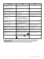
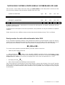
r = parameters for the temperature regulation
REGULATION PARAMETERS Type Min. Max. U.m. Def.
rd Regulation delta (differential) F 0.1 +19.9 °C/°F 2
r1 Set minimum allowed C -40 r2 °C/°F -40
r2 Set maximum allowed C r1 +199 °C/°F 90
r3 Direct/reverse operation (Dir r3=0, rev r3=1;IR32S only) C 0 1 flag 0
Note: for the set times to become operative, the instrument must be switched off and on again.
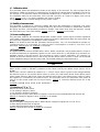
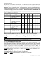
rd: Regulation delta
Sets the value of the differential, or hysteresis, used in regulating the temperature. A narrow differential, i.e.
one with a low number, ensures a temperature which differs little from the setpoint (or optimal operating
temperature), but which requires frequent switching on and off of the main operating components (normally
the compressor). It is possible to prolong the life of the compressor by appropriately setting the parameters
to define the number of start-ups per hour and the minimum switch-off period (see the Compressor
parameters).
In all Infrared refrigeration equipment the differential is placed to the right of the setpoint as indicated below
(DIRECT operation):
Default: rd=2. Available on IR32S, IRDRSE/S0, IR32Y, IR32P, IR32C and IRDRC. Parameter with direct
access from remote commander.
r1: SET minimum allowed
This parameter sets the minimum value that can be given to the setpoint. Using this parameter prevents the
user from fixing a setpoint lower than the value assigned to r1. Default: -40. Available on IR32S,
IRDRSE/S0, IR32Y, IR32P, IR32C and IRDRC.
r2: SET maximum allowed
This parameter sets the maximum value accepted as a setpoint. Use of this parameter prevents the user
from fixing a setpoint greater than the value assigned to r2. Default: +90. Available on IR32S, IRDRSE/S0,
IR32Y, IR32P, IR32C and IRDRC.
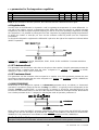
r3: DIRECT/REVERSE
Model IR32S is also designed to operate as a thermostat (parameter H1=0, see below). In "thermostat"
operation it is possible to select the function "cooling" (or DIRECT, as typically used in refrigeration) or the
function "heating" (or REVERSE, as used typically in heating). It should be remembered that in the
REVERSE mode the differential is to the left of the setpoint as indicated in the diagram below. Model IR32S
has a further parameter in the "r" category for selecting the mode of operation, parameter r3.
When r3=0 you have the DIRECT operation (refrigeration). When r3=1 you have the REVERSE operation
(heating). See also the description of parameter A4. Default: r3=0 (DIRECT) with H1=0 on model IR32S,
IRDRSE/S0. This parameter is not available on other models. Available on IR32S, IRDRSE/S0.
For the r3, r4, r5, rt, rH, rL parameters: see the following chapter “Notes for the new release” to a more detailed
description of this parameter functionalities, effective for the instrument with serial number greater than 100,000)

Cod. +030220151 - Rel. 2.1 - 04/09/98
19
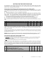
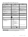
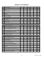
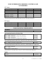
c = parameters for the compressor management
COMPRESSOR PARAMETERS Type Min. Max. U.m. Def.
c0 Delay in compressor insertion after switching on equipment C 0 15 mins 0
c1 Minimum time between two successive insertions of
compressor
C 0 15 mins 0
c2 Minimum compressor down time C 0 15 mins 0
c3 Minimum compressor operating time C 0 15 mins 0
c4 Duty setting (compressor safety: 0=OFF, 1=ON) C 0 100 mins 0
cc Duration of continuos cycle C 0 15 hrs 4
c6 Alarm cut-out after continuos cycle C 0 15 hrs 2
Note: for the set times to become operative, the instrument must be switched off and on again.
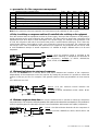
c0 Delay in switching on compressor and fans (if controlled) after switching on the equipment.
From the moment when the equipment receives its power supply, start-up of the compressor is delayed by a
period equivalent to the value assigned to this parameter. This delay serves to protect the compressor from
repeated start-ups when there is some interruption in the power supply. For example, if the paramater is set
at c0=6, the compressor will wait for six minutes after power is restored before starting up. Thus if there are
several power failures close together (in this case at intervals of less than six minutes), the compressor will
not start up. In the case of installations with more than one compressor, the parameter A0 can also be used
to avoid simultaneous start-ups of several compressors; it is sufficient to assign a different value to A0 for each
compressor.
Default: c0=0 (no minimum period is assigned to the
delay between switching on equipment and activation of
the compressor). Available on IR32S, IRDRSE/S0,
IR32Y, IR32P, IR32C and IRDRC
c1: Minimum time between two start-ups of compressor.
This sets the minimum time in minutes which must elapse between two insertions of the compressor,
independently of the temperature and of the setpoint. By setting this parameter it is possible to restrict the
number of start-ups per hour. For example, if the greatest number of start-ups permitted in an hour must be
10,
it is sufficient to set c1=6.
Default: c1=0 (No minimum interval between two
insertions is set.)
Available on IR32S, IRDRSE/S0, IR32Y, IR32P, IR32C
and IRDRC.
c2: Minimum compressor down-time: this sets the minimum time in minutes for which the compressor
may remain inactive. The compressor will not be started up if the minimum time selected has not elapsed (c2). This parameter is
useful for equalising pressure after switch-off in the case of installations with hermetic and capillary compressors.
Default: c2=0 (No minimum down-time for the compressor is
set.)
Available on IR32S, IRDRSE/S0, IR32Y, IR32P, IR32C and
IRDRC.
La pagina si sta caricando...
La pagina si sta caricando...
La pagina si sta caricando...
La pagina si sta caricando...
La pagina si sta caricando...
La pagina si sta caricando...
La pagina si sta caricando...
La pagina si sta caricando...
La pagina si sta caricando...
La pagina si sta caricando...
La pagina si sta caricando...
La pagina si sta caricando...
La pagina si sta caricando...
La pagina si sta caricando...
La pagina si sta caricando...
La pagina si sta caricando...
La pagina si sta caricando...
La pagina si sta caricando...
La pagina si sta caricando...
La pagina si sta caricando...
La pagina si sta caricando...
La pagina si sta caricando...
La pagina si sta caricando...
La pagina si sta caricando...
La pagina si sta caricando...
La pagina si sta caricando...
La pagina si sta caricando...
La pagina si sta caricando...
La pagina si sta caricando...
La pagina si sta caricando...
La pagina si sta caricando...
La pagina si sta caricando...
La pagina si sta caricando...
La pagina si sta caricando...
La pagina si sta caricando...
La pagina si sta caricando...
La pagina si sta caricando...
La pagina si sta caricando...
La pagina si sta caricando...
La pagina si sta caricando...
La pagina si sta caricando...
La pagina si sta caricando...
La pagina si sta caricando...
-
 1
1
-
 2
2
-
 3
3
-
 4
4
-
 5
5
-
 6
6
-
 7
7
-
 8
8
-
 9
9
-
 10
10
-
 11
11
-
 12
12
-
 13
13
-
 14
14
-
 15
15
-
 16
16
-
 17
17
-
 18
18
-
 19
19
-
 20
20
-
 21
21
-
 22
22
-
 23
23
-
 24
24
-
 25
25
-
 26
26
-
 27
27
-
 28
28
-
 29
29
-
 30
30
-
 31
31
-
 32
32
-
 33
33
-
 34
34
-
 35
35
-
 36
36
-
 37
37
-
 38
38
-
 39
39
-
 40
40
-
 41
41
-
 42
42
-
 43
43
-
 44
44
-
 45
45
-
 46
46
-
 47
47
-
 48
48
-
 49
49
-
 50
50
-
 51
51
-
 52
52
-
 53
53
-
 54
54
-
 55
55
-
 56
56
-
 57
57
-
 58
58
-
 59
59
-
 60
60
-
 61
61
-
 62
62
-
 63
63


Carel IR32C Manuale utente
- Tipo
- Manuale utente
in altre lingue
- English: Carel IR32C User manual
Documenti correlati
-
Carel iR Series Manuale utente
-
-
-
-
-
Carel heaterSteam Manuale utente
-
Carel SmartCella 3PH WP00B24A10 Quick Manual
-
-
-
Altri documenti
-
Robertshaw Ranco ETC Two Stage Electronic Temperature Control Manuale utente
-
-
-
-
Kegco ICXCK-1B-2 Manuale utente
-
Elvox 8017 Guida d'installazione
-
Omega CN245 Series Manuale del proprietario
-
Hitachi ATW-RTU-02 Istruzioni per l'uso
-
Trox X-CUBE X2 Istruzioni per l'uso
-
 CET LFM52 Manuale del proprietario
