Coemar DIGIfactor club 6x2,5Kw Manuale utente
- Categoria
- Misurazione, test
- Tipo
- Manuale utente

DIGIfactor club 6x2,5Kw
serial number
date of purchase
retailer
address
suburb
capital city
state
tel./fax/
Please note in the space provided above the relative service information of the model and the retailer from
whom you purchased your
DIGIfactor club 6x2,5Kw
: This information will assist us in providing spare parts,
repairs or in answering any technical enquiries with the utmost speed and accuracy.
WARNING: the security of the fixture is granted only if these instructions are strictly followed; therefore it is
absolutely necessary to keep this manual.
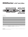
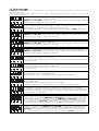
98
88
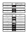
(2 Rack unit)
76
DIGIfactor club
6X2,5Kw
464
428
488
82
310
308
273
322
95

Index
1. Introduction
2. Technical characteristics
3. Mechanical installation
4. Connection to mains power
5. Load connection
6. Signal connection
6.1 DMX 512
6.2 0/+10VDC
7.Powering up
8. DMX addressing or analogue 0/+10v DC
8.1 0/+10V DC
8.2 DMX 512
9. Display panel functions
9.1.Test
9.1.1. Testing individual channels
9.2 Electrical and electronic displays
9.2.1. Voltage
9.2.2. Frequency
9.2.3. Temperature
9.2.4. DIGIfactor club 6x2,5Kw hours of operation
9.2.5. DMX 512 parameter displays
9.2.6. Individual channel DMX 512 input signal levels
9.2.7. Individual channel 0/+10V DC input signal levels
9.2.8. Instantaneous output voltage measurement on every channel
9.3 Advanced functions (installer options)
9.3.1. Lamp pre-heating
9.3.2. Setting individual channel output voltage limits
9.3.3. Setting channels to on/off operation (switching)
9.3.4. Switching channels - pre-heating
9.3.5. Setting dimming curves
9.3.6. Recording output levels
9.3.7. Restoring scenes from back-up
9.3.8. Overheating protection
9.3.9. DIGIfactor club 6x2,5Kw resetting
9.3.10. Viewing recorded scenes
9.3.11. Switching off pre-recorded scenes
10. Remote back-up scene restoration
11. Error messages
12. Maintenance
13. Spare parts
Coemar authorised services centres worldwide

1. Introduction
Congratulations on having purchased a new coemar product. You have ensured yourself of a controller of the highest quality,
both in the components and in the technology used.
In any request for information regarding the DIGIfactor club 6x2,5Kw. We ask that you specify correctly the model purcha-
sed. To this end we requst that you complete the purchase details listed below. This information will assist us in providing you
with prompt and accurate information.
2. Technical characteristics
DIGIfactor club 6x2,5Kw is a dimmer rack allowing control over the output of 6 channels from 0 to 230V. The six chan-
nels may be loaded to a maximum of 2,5KW; therefore resulting in a maximum current of 10 Amps per channel.
mechanical:
• Removeable enclosure panels allow easy internal inspection
• Maximum ambient operating temperature: 40 °C
• Weight: 7,5 Kg.
electrical:
• Power supply 230V three phase + N + E
• Voltage over-suply protection
• Load protection via ceramic fuses
• Maximum load per channel: 2,5KW
• Number of channels: 6.
• CE compliance
• Locking load connectors
• Locking supply connectors
• Fuse-blown indicator on all load outlets
electronics:
• Load voltages controlled by either 0/+10 v DC or DMX 512 signal
• Single channel test facility
• Digital DMX 512 addressing.
• Internal measurement of each of the three phases
• Internal measurement of supply frequency
• Instantaneous internal temperature measurement at the triacs
• Hours of operation counter
• DMX parameter measurement and display
• Individual channel pre-heating
• Variable maximum output limits for each channel
• Individual channels assignable as dimming or switching (on/off)
• Individual switching channel pre-heating(for trasformer loads).
• 9 scenes programmable in the DIGIfactor club 6x2,5Kw for use in absence of a control console
• Reset function
• DMX 512 via XLR 5/M socket
• Daisy chaining of DIGIfactor club 6x2,5Kw and other DMX 512 units via XLR 5/F plugs
• Internal +20 V DC powersupply
• 0/+10V DC via 8 pin Locking din
• 0-10 and DMX signal input measurement
• Output voltage display

3. Mechanical installation
Installation into a rack-case or a fixed installation should follow certain procedures to ensure correct operation of the unit.
Attention!
DIGIfactor club 6x2,5Kw is mechanically constructed to suit standard 19” rack mounting
Load voltage regulation is via internally mounted Triacs; these components will heat up when a load is connected; the
DIGIfactor club 6x2,5Kw needs to disappate this heat and for this reason the unit needs to be located in a well-ventila-
ted position, leaving a minimum of 2 centimetres clearance around the unit housing and any adjoining surfaces.
Note that on either side of the DIGIfactor club 6x2,5Kw there are forced-cooling air intake/exhaust passages. These pas-
sages should under no circumstances be covered.
Installation should not be onto a flammable surface; a hot housing is indicative of abnormal operating conditions.
Ambient operating temperature range: -10°C to +40°C.
If the ambient operating temperature exceeds that indicated, you may choose to install a forced-air cooling system into your
DIGIfactor club 6x2,5Kw rack case or mounting system to remove hot air from the housing.
After having installed the DIGIfactor club 6x2,5Kw refer to section 9.2.3 of this manual, ”Temperature testing” to comple-
te the correct installation of the unit.
Note that maximum operating temperature should be measured only after all load has been connected and been operating
for a minimum of one hour.

4. Connection to mains power
DIGIfactor club 6x2,5Kw is a dimmer rack suitable for power supply via 3 phase 230V.
230V single phase supply is possible, but will not allow the unit to be used in adherance to certain safety norms concerning
electrical operation and electromagnetic radiation emission.
Strict adherance to local regulatory requirements is essential; as is a correct and secure earth connection.
Ensure the supply cable is able to carry the maximum load for the unit.
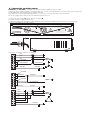
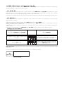
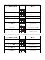
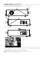
1) Loosen the four screws (A) which affix the rear panel (B).
2) Locate the power supply terminal strip
3) Slide your supply cable through the cable clamp till sufficient length is available for connection to the terminal strip.
4) Fix the cable clamp to the cable securely.
5) Connect the cable as shown in the diagram.
r
s
t
ph 1
ph 2
ph 3
neutro/neutral
terra/gnd
r
s
t
neutro/neutral
terra/gnd
380V ~
RST+N+
230V ~
terra/gnd
neutro/neutral
fase/phase
terra/gnd
neutro/neutral
fase/phase
ponte/link
ph 1
ph 2
ph 3
n1
n2
n3
terra/gnd
terra/gnd
230V ~
RST+
ponte/link
ponte/link
made in italy - Castel Goffredo (MN)
serial number
ATTENZIONE!
Alta tensione all'interno dell'apparecchio - Togliere tensione prima di rimuovere il pannello
Questa apparecchiatura deve essere installata esclusivamente da persone competenti,
seguendo scrupolosamente il manuale d'installazione fornito dalla ditta e le vigenti
normative. Una buona connessione di terra è essenziale
Contenitore caldo - 50°C in funzionamento normale, non installare su superficie
infiammabile Massima temperatura ambiente: 40°C
WARNING!
High voltage inside - Disconnect from supply before removing cover
This unit must be installed by a competent person in accordance
with the manufacturer's instructions and the safety norms.
A good earth connection is essential
Hot Case - 50 °C normal operation, Do not install on flammable surfaces.
Max ambience temperature: 40°C
Svitate le 4 viti per accedere alla connessione di potenza / Untighten 4 screws to access power terminal blocks
Caratteristiche di alimentazione:
Tensione: 200 - 260v AC trifase, collegamento
a stella (R S T +N + ) o triangolo
Frequenza: 50/60 Hz autoregolante
Assorbimento di corrente massimo: 20 A per fase
Carico massimo per canale: 10 A
Mains supply requirements:
Voltage:210 - 250v AC 3 phase, star
(R S T + N + ) or delta
Frequency: 50/60 Hz autosensing
Current requirement: 20 Amps per phase Max
Maximum load per channel: 10 Amps
B
A

protection
For proper powering up of the DIGIfactor club 6x2,5Kw we recommend the use of a termal/magnetic circuit breaker of
sufficient rating, as indicated in the diagram.
Attention
DIGIfactor club 6x2,5Kw is a high-technology dimmer running on mains power; only qualified personal should
perform installation, after thorough examination of this manual, and bearing in mind all local norms. Remove mains power
prior to removing the rear panel and performing any internal procedures.
The housing may be hot, 50°C during normal operation, do not install on flammable surfaces. Maximum ambient tempe-
rature: 40°C

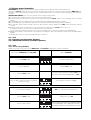
5. Load connection
DIGIfactor club 6x2,5Kw can control a maximum of 6 channels @ 2,5 Kw; with a maximum of 10 Amps per channel.
Do not overload the outlets!
Refer to local regualtions and norms with respect to the correct cabling required for connection of loads to dimmers in
public locations.
A good and secure earth connection is essential.
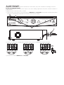
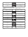
1) Loosen the four screw (A) on the rear panel (B) of the DIGIfactor club 6x2,5Kw; using a cable of suitable rating slide it
through the cable clamp (C) located on the rear of the unit and secure it firmly.
2) Connect the load cables, referring to the schematic shown, where a standard load is indicated by lamps.
3) Re-close the rear of the DIGIfactor club 6x2,5Kw.
GND
Terra
Load/Carico
ch5 n ch6n
5n 6n
Load/Carico
ch3 n ch4n
3n 4n
Load/Carico
ch1 n ch2n
1n 2n
A
made in italy - Castel Goffredo (MN)
serial number
ATTENZIONE!
Alta tensione all'interno dell'apparecchio - Togliere tensione prima di rimuovere il pannello
Questa apparecchiatura deve essere installata esclusivamente da persone competenti,
seguendo scrupolosamente il manuale d'installazione fornito dalla ditta e le vigenti
normative. Una buona connessione di terra è essenziale
Contenitore caldo - 50°C in funzionamento normale, non installare su superficie
infiammabile Massima temperatura ambiente: 40°C
WARNING!
High voltage inside - Disconnect from supply before removing cover
This unit must be installed by a competent person in accordance
with the manufacturer's instructions and the safety norms.
A good earth connection is essential
Hot Case - 50 °C normal operation, Do not install on flammable surfaces.
Max ambience temperature: 40°C
B
Svitate le 4 viti per accedere alla connessione di potenza / Untighten 4 screws to access power terminal blocks
Caratteristiche di alimentazione:
Tensione: 200 - 260v AC trifase, collegamento
a stella (R S T +N + ) o triangolo
Frequenza: 50/60 Hz autoregolante
Assorbimento di corrente massimo: 20 A per fase
Carico massimo per canale: 10 A
Mains supply requirements:
Voltage:210 - 250v AC 3 phase, star
(R S T + N + ) or delta
Frequency: 50/60 Hz autosensing
Current requirement: 20 Amps per phase Max
Maximum load per channel: 10 Amps
C
C

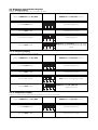
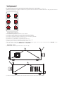
6. Signal connection
DIGIfactor club 6x2,5Kw operates on the two most common control signals used in the lighting industry:
digital DMX 512 and analogue 0/+10V dc.
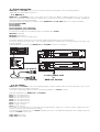
6.1 DMX 512
DIGIfactor club 6x2,5Kw receives, via an XLR 5 plug, 6 channels of DMX 512 digitally addressed as 1 to 6; using the
signals to to control the output levels of 6 channels in the range of 0 to 255, as per the DMX 512 standard, regulated by
USITT (U.S Intitute of Theatre Technology)
Connection between the DMX 512 controller and the DIGIfactor club 6x2,5Kw follows the recognised standard:
Pin 1= Ground (GND)
Pin 2= DATA -
Pin 3= DATA +
Pin 4= Optional - (not connected)
Pin 5= Optional + (not connected)
If required, the components for making up cables are available from coemar:
ME 4966 (Plug XLR 5)
ME 4965 (Socket XLR 5)
CV 4158 (two core screened cable Ø 0.5)
Connection should be via two core screened cable, following all protocols for screened signal cable.
Screening is always connected to pin 1 of the XLR plug and must be isolated from the metalic housing of the plug, with
regards to polarity.
A typical DMX 512 connection with DIGIfactor club 6x2,5Kw is shown in the diagram.
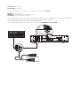
6.2 0/+10VDC
DIGIfactor club 6x2,5Kw receives via a Locking-din plug, 6 variable voltages from 0 to +10V continuous current, as per
international norms for analgoue transmission.
Connection is particualrly simple if the fixure receiving signal follows the coemar standard
Plug type Locking din 8 pin DIGIfactor club 6x2,5Kw
Pin 1= 0/+ 10 V DC channel 1
Pin 2= 0/+ 10 V DC channel 2
Pin 3= 0/+ 10 V DC channel 3
Pin 4= 0/+ 10 V DC channel 4
Pin 5= 0/+ 10 V DC channel 5
Pin 6= 0/+ 10 V DC channel 6
Pin 7= supply + 20 V DC
Pin 8= 0V DC reference
Pin number 7 is connected to an internal +20 V DC regulated power supply; this is useful as a power supply source for a
number of consoles which operate on this voltage.
If the contol console operates on the coemar standard, you may use the following locking din cables available from you
authorised coemar service centre:
Code: 247 (5m length)
Code: 248 (10m length)
5 pin XLR 5/F
5 pin XLR 5/M
1
DIGIfactor club
6X2,5Kw
Control input/Segnale d'ingresso:
0 to /+10v
out
in
Control input:
Segnale d'ingresso:
DMX 512
pin1: gnd
pin2: data -
pin3: data +
pin4: optional -
pin5: optional +
pin1: ch1...pin6: ch6
pin7: supply +20V 100mA max
pin8: shell 0v
DIGIfactor club
6X2,5Kw
Control input/Segnale d'ingresso:
0 to /+10v
out
in
Control input:
Segnale d'ingresso:
DMX 512
pin1: gnd
pin2: data -
pin3: data +
pin4: optional -
pin5: optional +
pin1: ch1...pin6: ch6
pin7: supply +20V 100mA max
pin8: shell 0v
dmx 512
standard
out
3
2
in
in
out
out
to other power unit
or
DMX 512 Devices

Code: 249 (25m length)
Code: 250 (50m length)
If required, componts for the manufacture of cable can be ordered from coemar:
ME 261 (Locking-din plug)
CV 924 (screened 8 core cable Ø 0.25, per metre)
CV 4158 (8 core cable Ø 0.25, per metre)
We recommend the use of screened cable; particularly in situations where the possiblity of electromagnetic disturbance is
high, to reduce to a minimum the possible causes of incorrect functioning of equipment.
Screening should alwasy be connected to pin 8 of the locking-din.
Shown is a typical 0/+10v DC connection between controller and DIGIfactor club 6x2,5Kw.
8 pin locking DIN/M
8 pin locking DIN/M
DIGIfactor club
6X2,5Kw
Control input/Segnale d'ingresso:
0 to /+10v
out
in
Control input:
Segnale d'ingresso:
DMX 512
pin1: gnd
pin2: data -
pin3: data +
pin4: optional -
pin5: optional +
pin1: ch1...pin6: ch6
pin7: supply +20V 100mA max
pin8: shell 0v
control output:
0/+10v
segnale di uscita:
in
3
4
5
6
7
8
2
1
in
Control input/Segnale d'ingresso:
0 to /+10v
out
pin1: gnd
pin2: data -
pin3: data +
pin4: optional -
pin5: optional +
pin1: ch1...pin6: ch6
pin7: supply +20V 100mA max
pin8: shell 0v

7. Powering up
After having carefully followed the instructions regarding electrical connection and mechanical fixing, the DIGIfactor club
6x2,5Kw may now be powered up via an thermal/magnetic circuit breaker as described in section 4.
Upon powering up, the display will run through a test/reset procedure which begins with a display of the software version instal-
led in the unit, followed by a measurement of the current operating frequency of the power supply and auto-optimisation of the
unit’s operation. DIGIfactor club 6x2,5Kw will also display the voltage above 250V or below 180V.
When the display shows A001(or any other value preceded by the letter A), the DIGIfactor club 6x2,5Kw is ready for normal
operation.
Attention!
If the start-up procedure is not as described above, and the display does not come on, it may be that the power supply is
not connected properly; refer to section 4 to re-check connection.
If the display should come on signaling other than that described above, refer to your authorised coemar service centre for
further advice

8. DMX addressing or analogue 0/+10v DC
As described in section 6 you may use the DIGIfactor club 6x2,5Kw with either 0/+10V DC or DMX 512 control signals;
depending upon the requirements of your controller
8.1 0/10 v DC
After having correctly connected the cable, channel number 1 of the DIGIfactor club 6x2,5Kw corresponds to the signal
being sent via pin 1 of the Locking DIN; channel number 2 corresponds to the signal being sent via pin 2 of the Locking
DIN, and so on until the 6th channel being via pin number 6 of the Locking DIN.
A variation in the voltage from 0 to 10 V of the control signal corresponds to a variation of the load voltage from 0 to 230 V.
8.2 DMX 512
After correct connection of the DMX 512 signal cable, the 6 channels of the dimmer are controlled via 6 channels of your
DMX controller in sequence.
Upon first turning on the dimmer’s display shows A001 indicating the address DMX 1.
A dimmer so addressed will respond to channels 1 through 6 of the DMX 512 controller, a second dimmer should be
addressed as 7, and so on in multiples of 6.
A dimmer can therefore respond to whichever 6 sequential channels of the controller you wish simply by changing the
display’s address.
Note that after the first address is set, DIGIfactor club 6x2,5Kw will also occupy the next 5 addresses as well.
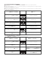
changing the dmx address
Important Note: Keeping the + or- buttons depressed will cause the display to scroll at high speed, allowing for rapid
chaing ing .
The presence of DMX signal is indicated by the flashing led in the DMX input display.
dmx
input display
function display
PConfirms your selection of address, the display
stops flashing and the unit responds to the new
DMX 512 address.
function display
Press the enter button
Shows the DMX addresses from 1 to 501, the led
display will flash, indicating that the change has
not been recorded yet, for example, 7
function display
Press the + or - buttons until the desired channel
is shown
Address DMX 001Power up the DIGIfactor club 6x2,5Kw

9. Display panel functions
Attention! the display panel controls the proper functioning of the dimmer and its various parameters.
Altering the coemar factory presents can vary the functioning of the dimmer, causing it to not respond to DMX 512 con-
trol signal; careful and thorough reading of all the following procedures is therefore recommended prior to altering any
functions.
IMPORTANT NOTES: these notes are valid for all the functions which follow
1. Keeping the + or i- buttons depressed for 8 seconds for rapid scrolling.
2. You may abort the altering of any function by simply pressing the menu button until the display shows the DMX
address
3. To immediately go to the maximum value, press the + button whilst simultaneously pressing the - button.
4. To immediatley go to the minimum value, press the - button whilst simultaneously pressing the + button.
5. You may alter single channel settings or press the + or - buttons until the display shows ALL to alter all channels simulta-
neously.
6.
Changes made via the menu buttons are confirmed and recorded when the enter button is pressed.
It is always possible to over-write any settings with new ones at any time.
The reset procedure allows all settings to be returned to factory presets, with the exception of the DMX address.
7.
Display panel functions remain active for 10 secondis if no changes are made, after which they will return to the DMX address
display/
The display panel has three menus and main functions, which are:
9.1. Test
9.2. Electical and electronic displays
9.3. Advanced functions (installer options)
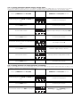
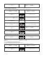
9.1. Test
9.1.1. Tests every channel
Allows the testing of every outlet of the DIGIfactor club 6x2,5Kw, without the need for a controller
You may repeat the test on any individual channel, or, alternatively:
Select an output level from 0 to 99 (maximum output);
via the digital display. As the display value increases,
note that the output level of the load does the same.
function display
Press the + or - button
Output level set to 00
function display
Press the enter button
ALL to test all channels simultaneously
function display
Press the + or - buttons
For example, test channel 6 (t 6)
function display
Press the + or - buttons to select the required
channel for testing
To confirm your selection of channel test, the
first channel for testing is displayed as 1 (t 01).
Press the enter button
Channel test menuPress the + button
electronics display menu
function display
Press the menu button
Address DMX 001Power up the DIGIfactor club 6x2,5Kw

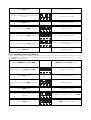
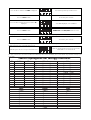
9.2 Electrical and electronic displays
9.2.1. Voltage display
Displays the input voltage across the three phases (in volts).
9.2.2. Frequency display
Displays the input voltage frequency (in Hertz).
9.2.3. Temperature display
Displays the instantaneous temperature of the dimmer’s internals (in centigrade).
To confirm your selection
Press the enter button
Electronic display menu
function display
Press the menu button
DIGIfactor club 6x2,5Kw turns onPower up DIGIfactor club 6x2,5Kw
DIGIfactor club 6x2,5Kw FrE measures the
frequency in Hertz
function display
Press the enter button
FrE measures the frequency in Hertz
function display
Press the + or - button
To confirm your selection
Press the enter button
Electronic display menu
function display
Press the menu button
DIGIfactor club 6x2,5Kw turns onPower up DIGIfactor club 6x2,5Kw
DIGIfactor club 6x2,5Kw measures the volta-
ge across one phase, for example phase1 voltage
is 230v
function display
Press the enter button
voltage displayed
function display
Press the + or - buttons
To confirm your selection
Press the enter button
Electronic display menu
function display
Press the menu button
DIGIfactor club 6x2,5Kw turns onPower up DIGIfactor club 6x2,5Kw

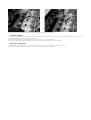
The maximum operating temperature of the unit is 65°C. If under full load for some hours the temperature should exceed
65°, re-check the mechanical installation of the unit, which may be incorrect. The forced cooling system may be obstructed,
the fan itself may be functioning incorrectly; or simply the unit’s cooling system may not be situated in a suitable position to
allow heat to be disappated sufficiently.
In such an instance, the addition of a further fan at the base of the unit, may be appropriate.
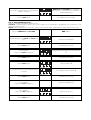
9.2.4. DIGIfactor club 6x2,5Kw hours of operation
Displays the number of hours that the DIGIfactor club 6x2,5Kw has been operated (in hours)
9.2.5. DMX 512 parameters display
Displays significant parameters of the DMX 512 signal, bringing any problems to light
To confirm your selection
Press the enter button
SEr displays significant parameters of the
DMX 512 signal
function display
Press the + or - button
To confirm your selection
Press the enter button
Electronic display menu
function display
Press the menu button
DIGIfactor club 6x2,5Kw turns onPower up DIGIfactor club 6x2,5Kw
DIGIfactor club 6x2,5Kw displays the amount
of time, in hours, it has been operational, for
example, 30.
function display
Press the enter button
HoUr display in hoursPress the + or - button
To confirm your selection
Press the enter button
Electronic menu display
function display
Press the menu button
DIGIfactor club 6x2,5Kw turns onPower up DIGIfactor club 6x2,5Kw
DIGIfactor club 6x2,5Kw displays the tempe-
rature, measured at the triacs
function display
Press the enter button
tEMP temperature display in °C
function display
Press the + or - buttons

Ymay now display various DMX 512 parameters
Recommended values: Minimum 1, maximum 44 Hz.
or
Refer to section 12 for information regarding error messages
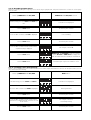
9.2.6. Individual channel DMX 512 input signal levels
Displays the DMX level (from 0 to 255) which is being outputted by the controller to each of the 6 channels
DIGIfactor club 6x2,5Kw will display the
incoming DMX 512 signal level of the selected
channel, for example a level of 255.
function display
Press the enter button
For example, channel number 6
function display
Press the + or - button to select the next channel
you wish to display
Channel number 1
function display
Press the enter button
To measure the incoming DMX 512 signal levels
function display
Press the + or - button until dMX is displayed
To confirm your selection
Press the enter button
Input signal display menu
function display
Press the + or - button until InSG is displayed
Electronic display menu
function display
Press the menu button
DMX addressPower up DIGIfactor club 6x2,5Kw
DIGIfactor club 6x2,5Kw displays the reading
function display
Press the enter button
Strt the first bit after a reset signal (DMX)
function display
Press the + or - button
DIGIfactor club 6x2,5Kw displays the value in
Hertz
function display
Press the enter button
rAtE measures the frequency at which
DIGIfactor club 6x2,5Kw receives a new
packet of signal (DMX)
Press the + or - button

9.2.7. Individual channel 0/+10V DC input signal levels
Displays the 0/+10V DC level (decimal from 0 to 10) which is being outputted by the controller to each of the 6 channels
9.2.8. Individual channel output voltage levels
Displays the instantaneous output level (in volts) of each of the 6 channels. The display may be the result of an output volta-
ge as determined by the controller, or of an in-built function of the dimmer, such as swithing channel pre-heating.
Channel number 1
function display
Press the enter button
To confirm your selection
Press the enter button
Output voltage display menu
function display
Press the + or - button until Outv is displayed
Electronic display menu
function display
Press the menu button
DMX addressPower up DIGIfactor club 6x2,5Kw
DIGIfactor club 6x2,5Kw will display the inco-
ming 0/+10v signal level of the selected channel,
for example a level of 8 volts
function display
Press the enter button
For example, channel number 6
function display
Press the + or - button to select the next channel
you wish to display
Channel number 1
function display
Press the enter button
To measure the incoming 0/10V signal
function display
Press the + or - button until 0-10 is displayed
Measure the incoming signal level
Press the enter button
Input signal display menu
function display
Press the + or - button until InSG is displayed
Electronic display menu
function display
Press the menu button
DMX addressPower up DIGIfactor club 6x2,5Kw

9.3. Advanced functions (installer options)
ATTENTION! Modifying these settings will modify the operation of the DIGIfactor club 6x2,5Kw. Use these functions only
when necessary.
9.3.1. Lamp pre-heating
Causes sufficient voltage to be applied to the lamp load to assist in preventing lamp failure due to large thermal differences
between lamp on and lamp off states.
NOTE: ATTENTION! You may set individual pre-heat values for each channel or, by pressing the + or - buttons till ALL
is displayed, you may address and set all the channels simultaneously
The voltage value selected above is calculated as a percentage of the input voltage, for ease of use. DIGIfactor club
6x2,5Kw will display a value which is an approximation, not an accuracte reading.
To set the level in memory
Press the enter button
DIGIfactor club 6x2,5Kw sets the dimmer
channel(s) to the set minimum level, regardless of
incoming DMX signal
function display
Press the + or - buttons until the required level is
achieved.
Pre-heating set at level 0
function display
Press the enter button
For example, number 6
function display
Press the + or - button until the required channel
is selected
To confirm your selection
Press the enter button
To display the lamp pre-heat menu PrEH
function display
Press the + or - button
To confirm your selection
Press the enter button
Function menu displayed
function display
Simultaneously press the menu and enter but-
tons
DIGIfactor club 6x2,5Kw turns onPower up DIGIfactor club 6x2,5Kw
DIGIfactor club 6x2,5Kw will display the RMS
output voltage of the selected channel (in volts).
For example, 230 volts.
function display
Press the enter button
For example, channel number 12
function display
Press the + or - button to select the next channel
you wish to display

9.3.2. Setting individual channel output voltage limits
Sets a maximum output voltage (between the maximum output voltage and 180V) which the selected channel can achieve.
Suitable if the dimmer is located close to the generator or sub-station by preventing lamp failure due to over-voltage supply.
9.3.3. Setting channels to on/off operation (switching)
Allows selected channels to be set to on/off only. The channel will remain off up to 50% and on from 50% to 100%, it will
not allow the voltage to be regulated to any other value.
switching (on/off) or dimming menu is
displayed
function display
Press the + or - buttons until FUnc is displayed
To confirm your selection
Press the enter button
Function menu displayed
function display
Simultaneously press the menu and enter but-
tons
DIGIfactor club 6x2,5Kw turns onPower up DIGIfactor club 6x2,5Kw
To confirm your selection
Press the enter button
You may reduce the voltage down to 180V
function display
Press the + or - button
Maximum output voltage is selected.
function display
Press the enter button
For example, channel 4
function display
Press the + or - button to select the required chan-
nel
To confirm your selection
Press the enter button
Maximum output voltage menu displayed SEtv
function display
Press the + or - button
To confirm your selection
Press the enter button
Function menu displayed
function display
Simultaneously press the menu and enter but-
tons
DIGIfactor club 6x2,5Kw turns onPower up DIGIfactor club 6x2,5Kw

9.3.4. Switching channel pre-heating
Causes sufficient voltage to be applied to the channel’s load to assist in preventing lamp/transformer failure due to large
thermal differences between fixture on and off states.You may select this function only if the channels have been set to swit-
ching ScH1 as described above.
Pv00 pre-heat at level 0
function display
Press the enter button
For example, channel 6 previously set to ScH1
function display
Press the + or - button until the required channel
is selected
To confirm your selection
Press the enter button
Lamp pre-heating
function display
Press the + or - button until PrEH is displayed
To confirm your selection
Press the enter button
Function menu displayed
function display
Simultaneously press the menu and enter but-
tons
DIGIfactor club 6x2,5Kw turns onPower up DIGIfactor club 6x2,5Kw
To confirm your selection
Press the enter button
Transformer switching function (allows pre-heat to
be assigned)
function display
Press the + or - button until ScH1 is displayed
Switching standard function
function display
Press the + or - button until ScH0 is displayed
Dimmer function
function display
Press the + or - button until cdiM is displayed
To confirm your selection
Press the enter button
For example, channel 1
function display
Press the + or - buttons until the required channel
is selected.
To confirm your selection
Press the enter button

9.3.5. Stting dimming curves
Allows the selection of two distinct dimming curves.
standard, a standard lighting response curve, where response to the control slider is proportional, thus resulting in the stan-
dard “S” type dimming curve.
lineare, a linear dimming curve where the response to the control slider is equal along the length of travel of the slider.
oppure
To confirm your selection
Press the enter button
Setting the linear curve
function display
Press the + or -
buttons until LIn is displayed
Setting the standard curve
Press the + or -
buttons until Strd is displayed
To confirm your selection
Press the enter button
For example, channel number 6
function display
Press the + or - button until the required channel
is selected
Channel number 1
function display
Press the enter button
To confirm your selection
Press the enter button
Setting the type of dimming curve for each chan-
nel
function display
Press the + or -
buttons until CUrv is displayed
To confirm your selection
Press the enter button
Function menu displayed
function display
Simultaneously press the menu and enter but-
tons
DMX addressPower up DIGIfactor club 6x2,5Kw
To record the level in memory
Press the enter button
DIGIfactor club 6x2,5Kw sets the dimmer
channel(s) to the set minimum level, regardless of
incoming DMX signal
function display
Press the + or - button until the required output
voltage is achieved
La pagina si sta caricando...
La pagina si sta caricando...
La pagina si sta caricando...
La pagina si sta caricando...
La pagina si sta caricando...
La pagina si sta caricando...
La pagina si sta caricando...
La pagina si sta caricando...
La pagina si sta caricando...
La pagina si sta caricando...
La pagina si sta caricando...
-
 1
1
-
 2
2
-
 3
3
-
 4
4
-
 5
5
-
 6
6
-
 7
7
-
 8
8
-
 9
9
-
 10
10
-
 11
11
-
 12
12
-
 13
13
-
 14
14
-
 15
15
-
 16
16
-
 17
17
-
 18
18
-
 19
19
-
 20
20
-
 21
21
-
 22
22
-
 23
23
-
 24
24
-
 25
25
-
 26
26
-
 27
27
-
 28
28
-
 29
29
-
 30
30
-
 31
31


Coemar DIGIfactor club 6x2,5Kw Manuale utente
- Categoria
- Misurazione, test
- Tipo
- Manuale utente