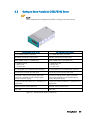
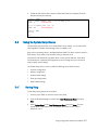
Bull NovaScale 3005 Installation and Guida utente
- Categoria
- Server
- Tipo
- Guida utente
Questo manuale è adatto anche per

NovaScale 3005
Series
Installation and User's Guide
NOVASCALE
REFERENCE
86 A1 02ET 05


NOVASCALE
NovaScale 3005 Series
Installation and User's Guide
Hardware
February 2007
BULL CEDOC
357 AVENUE PATTON
B.P.20845
49008 ANGERS CEDEX 01
FRANCE
REFERENCE
86 A1 02ET 05

The following copyright notice protects this book under Copyright laws which prohibit such actions as, but not limited
to, copying, distributing, modifying, and making derivative works.
Copyright © Bull SAS
2006-2007
Copyright © HITACHI, Ltd. 2006-2007
Printed in France
Suggestions and criticisms concerning the form, content, and presentation of this
book are invited. A form is provided at the end of this book for this purpose.
To order additional copies of this book or other Bull Technical Publications, you
are invited to use the Ordering Form also provided at the end of this book.
Trademarks and Acknowledgements
We acknowledge the right of proprietors of trademarks mentioned in this book.
Intel
®
and Itanium
®
are registered trademarks of Intel Corporation.
Windows
®
and Microsoft
®
software are registered trademarks of Microsoft Corporation.
UNIX
®
is a registered trademark in the United States of America and other countries licensed exclusively through the
Open Group.
Linux
®
is a registered trademark of Linus Torvalds.
The information in this document is subject to change without notice. Bull will not be liable for errors
contained herein, or for incidental or consequential damages in connection with the use of this material.

iii
Table of Contents
Preface.................................................................................................................. ix
Intended Readers ........................................................................................................................ ix
Highlighting ............................................................................................................................... ix
Related Publications...................................................................................................................... x
Regulatory Specifications and Disclaimers ...................................................................................... xi
Declaration of the Manufacturer or Importer...............................................................................xi
Safety Compliance Statement...................................................................................................xi
European Community (EC) Council Directives.............................................................................xi
International Electrotechnical Commission (IEC) Statement ..........................................................xii
Federal Communications Commission (FCC) Statement...............................................................xii
FCC Declaration of Conformity...............................................................................................xiii
Canadian Compliance Statement (Industry Canada) .................................................................xiii
Laser Compliance Notice.......................................................................................................xiii
Definition of Safety Notices .........................................................................................................xiv
Electrical Safety .........................................................................................................................xiv
Laser Safety Information ...............................................................................................................xv
Data Integrity and Verification.......................................................................................................xv
Environmental Regulation .............................................................................................................xv
Chapter 1. Delivery........................................................................................ 1-1
1.1 General Recommendations.................................................................................................. 1-1
1.1.1 Delivery ................................................................................................................ 1-1
1.1.2 Important Safety Instructions .................................................................................... 1-2
1.1.3 Installation Environment .......................................................................................... 1-3
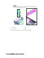
1.2 Unpacking the Server Cabinet ............................................................................................. 1-3
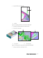
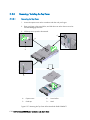
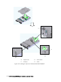
1.3 Unpacking and Installing a Server Drawer............................................................................. 1-3
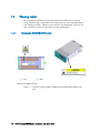
1.4 Warning Labels................................................................................................................. 1-4
1.4.1 Novascale 3025/3045 Servers .............................................................................. 1-4
1.4.2 Novascale 3045 COMPACT Server......................................................................... 1-6
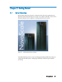
Chapter 2. Getting Started .............................................................................. 2-1
2.1 Server Overview................................................................................................................ 2-1
2.2 Server Features.................................................................................................................. 2-2
2.3 Getting to Know NovaScale 3025/3045 Server.................................................................... 2-3
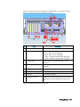
2.3.1 Server Drawer Front Components ............................................................................ 2-5
2.3.2 Server Drawer Rear Components ........................................................................... 2-10
2.3.3 Server Drawer Internal Features (Top View)............................................................. 2-13
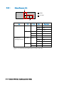
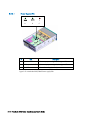
2.3.4 Power Supply Subsystem ...................................................................................... 2-13
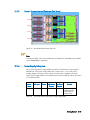
2.3.5 Cooling Subsystem............................................................................................... 2-15
2.3.6 PCI Card Slots ..................................................................................................... 2-16

iv Bull NovaScale 3005 Series - User's Guide
2.4
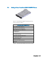
Getting to Know NovaScale 3045 COMPACT Server........................................................... 2-17
2.4.1 Server Drawer Front Components........................................................................... 2-18
2.4.2 Server Drawer Rear Components ........................................................................... 2-22
2.4.3 Internal Server Drawer Features (Top View) ............................................................. 2-24
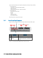
2.4.4 Power Supply Subsystem....................................................................................... 2-24
2.4.5 Cooling Subsystem............................................................................................... 2-25
2.4.6 PCI Card Slot....................................................................................................... 2-27
2.5 Connecting the Monitor, Keyboard and Mouse ....................................................................2-28
2.6 Connecting the Server to the Site Power Supply....................................................................2-28
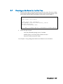
2.7 Powering on the Server for the First Time ............................................................................. 2-29
Chapter 3. Using Configuration Software and Utilities..........................................3-1
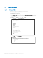
3.1 Using the EFI Boot Manager ................................................................................................3-1
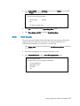
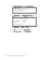
3.2 Using the EFI Shell..............................................................................................................3-4
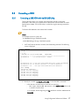
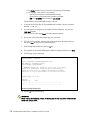
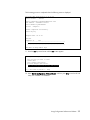
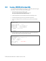
3.3 Formatting a HDD ..............................................................................................................3-7
3.3.1 Formatting a SAS HDD with the LSI SAS Utility........................................................... 3-7
3.3.2 Formatting a SATA HDD with the diskpart Utility ...................................................... 3-10
3.4 Using the System Setup Menus........................................................................................... 3-11
3.4.1 Starting Setup ...................................................................................................... 3-11
3.4.2 Recording Setup Settings....................................................................................... 3-12
3.4.3 Using Setup Screens ............................................................................................. 3-12
3.4.4 Primary Setup Screen............................................................................................ 3-12
3.5 Setting the Console .......................................................................................................... 3-16
3.5.1 On-board VGA.................................................................................................... 3-16
3.5.2 Serial Console ..................................................................................................... 3-17
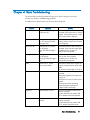
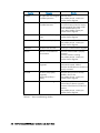
Chapter 4. Basic Troubleshooting......................................................................4-1
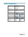
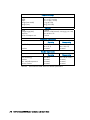
Appendix A. Server Specifications...................................................................... A-1
Appendix B. Mounting the Server Drawer in the Cabinet ........................................B-1
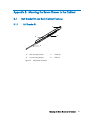
B.1 Rail Bracket Kit and Rack Cabinet Features............................................................................ B-1
B.1.1 Rail Bracket Kit ...................................................................................................... B-1
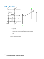
B.1.2 Rack Cabinet......................................................................................................... B-2
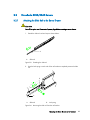
B.2 NovaScale 3025/3045 Servers .......................................................................................... B-3
B.2.1 Attaching the Slide Rail to the Server Drawer............................................................. B-3
B.2.2 Attaching the Guide Pin to the Rail Bracket Kit........................................................... B-5
B.2.3 Installing the Chassis in the Rack Cabinet.................................................................. B-6
B.3 NovaScale 3045 COMPACT Server................................................................................... B-14
B.3.1 Attaching the Slide Rail to the Server Drawer........................................................... B-14
B.3.2 Attaching the Guide Pin to the Rail Bracket Kit......................................................... B-16
B.3.3 Installing the Chassis in the Rack Cabinet................................................................ B-17

v
Appendix C. Adding / Removing Components......................................................C-1
C.1 General Recommendations..................................................................................................C-1
C.2 NovaScale 3025/3045 Servers ..........................................................................................C-2
C.2.1 Removing / Installing the Front Bezel ....................................................................... C-2
C.2.2 Removing / Installing the Top Cover ........................................................................ C-3
C.2.3 Installing / Removing / Hot-Swapping a Hard Disk Drive (HDD) ................................. C-4
C.2.4 Installing / Removing / Hot-Swapping a PCI Card................................................... C-12
C.3 NovaScale 3045 COMPACT Server...................................................................................C-21
C.3.1 Removing / Installing the Front Bezel ..................................................................... C-21
C.3.2 Removing / Installing the Top Cover ...................................................................... C-22
C.3.3 Removing / Installing a hard Disk Drive (HDD)........................................................ C-25
C.3.4 Removing / Installing a PCI Card........................................................................... C-31
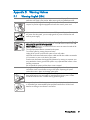
Appendix D. Warning Notices............................................................................D-1
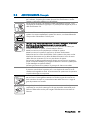
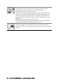
D.1 Warning: English (USA)......................................................................................................D-1
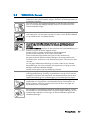
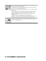
D.2 AVERTISSEMENTS: Français................................................................................................D-3
D.3 WARNUNG: Deutsch.........................................................................................................D-5
D.4 AVVERTENZA: Italiano .......................................................................................................D-7
D.5 ADVERTENCIA: Español .....................................................................................................D-9

vi Bull NovaScale 3005 Series - User's Guide
List of Figures
Figure 1-1.
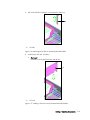
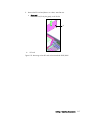
Location of Warning Labels on MMR and NovaScale 3025/3045 servers side ..................... 1-4
Figure 1-2. Location of Warning Labels on NovaScale 3025/3045 server rear...................................... 1-5
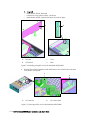
Figure 1-3. Location of Warning Labels on NovaScale 3045 COMPACT server...................................... 1-6
Figure 1-4. Location of Warning Labels on NovaScale 3045 COMPACT server rear............................... 1-6
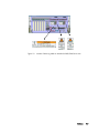
Figure 2-1. Bull NovaScale Server cabinets......................................................................................... 2-1
Figure 2-2. Bull NovaScale 3025 or 3045 server................................................................................ 2-3
Figure 2-3. NovaScale 3025/3045 Drawer front view........................................................................ 2-5
Figure 2-4. Control panel controls and LEDs........................................................................................ 2-6
Figure 2-5. DVD/CD-ROM RW Combo .............................................................................................. 2-8
Figure 2-6. Hard disk drive tray and status LED ................................................................................... 2-8
Figure 2-7. Memory box front view (MMR) and status of the LEDs.......................................................... 2-9
Figure 2-8. NovaScale 3045 Drawer rear view................................................................................. 2-10
Figure 2-9 NovaScale 3025 Drawer rear view................................................................................. 2-11
Figure 2-10. NovaScale 3025/3045 Ethernet connector status LEDs ..................................................... 2-12
Figure 2-11. NovaScale 3045 Drawer Top View................................................................................. 2-13
Figure 2-12. NovaScale 3025/3045 Power supply LEDs ..................................................................... 2-14
Figure 2-13. NovaScale 3025/3045 Cooling fan LED ........................................................................ 2-15
Figure 2-14. NovaScale 3025/3045 PCI card slot and LED................................................................. 2-16
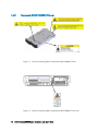
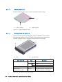
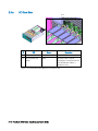
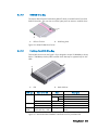
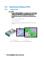
Figure 2-15 NovScale 3045 COMPACT Three Dimensional View ........................................................ 2-17
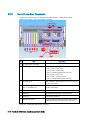
Figure 2-16 NovaScale 3045 COMPACT Server Drawer Front View.................................................... 2-18
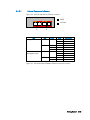
Figure 2-17. Control panel controls and LEDs...................................................................................... 2-19
Figure 2-18 DVD/CD RW Drive Carrier ............................................................................................2-21
Figure 2-19 NovaScale 3045 COMPACT Hard Disk Drive Tray and Status LED..................................... 2-21
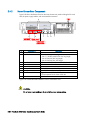
Figure 2-20. NovaScale 3045 COMPACT Server Drawer Rear View .................................................... 2-22
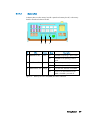
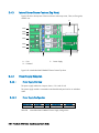
Figure 2-21 NovaScale 3045 COMPACT Ethernet Connectors Indicators.............................................. 2-23
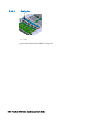
Figure 2-22 NovaScale 3045 COMPACT Server Drawer Top View...................................................... 2-24
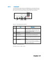
Figure 2-23. NovaScale 3045 COMPACT Power Supply Indicators ...................................................... 2-25
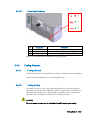
Figure 2-24 NovaScale 3045 COMPACT Cooling Fans...................................................................... 2-26
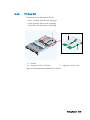
Figure 2-25 NovaScale 3045 COMPACT PCI Card Slots.................................................................... 2-27
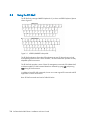
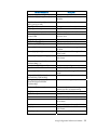
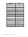
Figure 3-1. AZERTY/QWERTY lookup table ........................................................................................ 3-4
Figure 3-2. Security System Information screen - example ................................................................... 3-15
Figure B-1. Rail bracket kit features .................................................................................................... B-1
Figure B-2. Rack cabinet features....................................................................................................... B-2
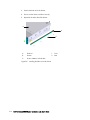
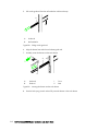
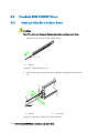
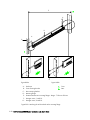
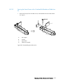
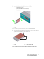
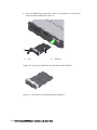
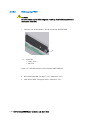
Figure B-3. Extending the slide rail..................................................................................................... B-3
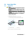
Figure B-4. Removing the slide rail from the rail bracket ....................................................................... B-3
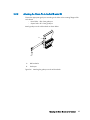
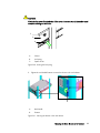
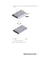
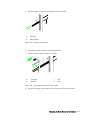
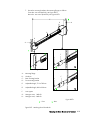
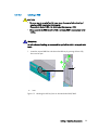
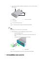
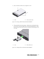
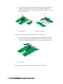
Figure B-5. Installing the slide rail on the drawer ................................................................................. B-4
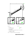
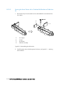
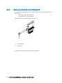
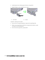
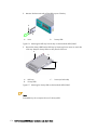
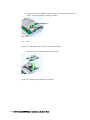
Figure B-6. Attaching the guide pins to the rail bracket kit .................................................................... B-5
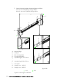
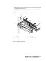
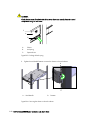
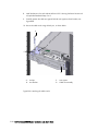
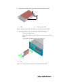
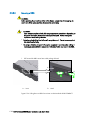
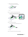
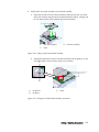
Figure B-7. Attaching the rail bracket kit to the mounting flange ............................................................ B-7
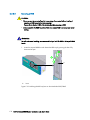
Figure B-8. Pulling out the guide rail................................................................................................... B-8
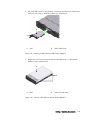
Figure B-9. Inserting the drawer into the rack cabinet........................................................................... B-8
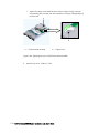
Figure B-10. Pushing the lock spring..................................................................................................... B-9
Figure B-11. Securing the drawer in the rack cabinet ............................................................................. B-9
Figure B-12. Disassembling the cable arm kit ...................................................................................... B-10
Figure B-13. Attaching the arm bracket .............................................................................................. B-11
Figure B-14. Attaching the rail bracket kit ........................................................................................... B-12
Figure B-15. Attaching the cable arm kit............................................................................................. B-13
Figure B-16. Extending the slide rail.................................................................................................. B-14

vii
Figure B-17. Removing the slide rail from the rail bracket .....................................................................B-14
Figure B-18. Installing the slide rail on the drawer ................................................................................B-15
Figure B-19. Attaching the guide pins to the rail bracket kit ..................................................................B-16
Figure B-20. Attaching the rail bracket kit to the mounting flange ..........................................................B-18
Figure B-21. Pulling out the guide rail.................................................................................................B-19
Figure B-22. Inserting the drawer into the rack cabinet.........................................................................B-19
Figure B-23. Pushing the lock spring ..................................................................................................B-20
Figure B-24. Securing the drawer in the rack cabinet...........................................................................B-20
Figure B-25. Disassembling the cable arm kit .......................................................................................B-21
Figure B-26. Attaching the arm bracket ..............................................................................................B-22
Figure B-27. Attaching the rail bracket kit...........................................................................................B-23
Figure B-28. Attaching the cable arm kit.............................................................................................B-24
Figure C-1. Removing the front bezel of the NovaScale 3025/3045 ..................................................... C-2
Figure C-2. Installing the front bezel of the NovaScale 3025/3045 ...................................................... C-2
Figure C-3. Removing the top cover of the NovaScale 3025/3045....................................................... C-3
Figure C-4. Installing the top cover of the NovaScale 3025/3045 ........................................................ C-3
Figure C-5. Unlocking the HDD tray lever on the NovaScale 3025/3045 .............................................. C-5
Figure C-6. Removing the HDD tray from the bay on the NovaScale 3025/3045 ................................... C-6
Figure C-7. Removing the dummy HDD on the NovaScale 3025/3045 ................................................. C-6
Figure C-8. Mounting the HDD in the HDD tray of the NovaScale 3025/3045....................................... C-7
Figure C-9. Inserting the HDD in the bay of the NovaScale 3025/3045 ................................................ C-7
Figure C-10. Unlocking the HDD tray lever on the NovaScale 3025/3045 .............................................. C-8
Figure C-11. Removing the HDD from the bay of the NovaScale 3025/3045 .......................................... C-9
Figure C-12. Removing the HDD from the HDD tray of the NovaScale 3025/3045................................... C-9
Figure C-13. Positioning the dummy HDD of the NovaScale 3025/3045............................................... C-10
Figure C-14. Inserting the HDD tray into the bay of the NovaScale 3025/3045 ..................................... C-10
Figure C-15. Unlocking the PCI card lock on the NovaScale 3025/3045 .............................................. C-12
Figure C-16. Removing the PCI filler on the NovaScale 3025/3045...................................................... C-13
Figure C-17. Installing a short PCI card on the NovaScale 3025/3045 ................................................. C-13
Figure C-18. Installing a long PCI card on the NovaScale 3025/3045.................................................. C-14
Figure C-19. Securing the PCI card on the NovaScale 3025/3045....................................................... C-14
Figure C-20. Unlocking the PCI card lock on the NovaScale 3025/3045 .............................................. C-16
Figure C-21. Removing a short PCI card on the NovaScale 3025/3045................................................ C-17
Figure C-22. Removing a long PCI card on the NovaScale 3025/3045 ................................................ C-18
Figure C-23. Installing the PCI filler on the NovaScale 3025/3045....................................................... C-19
Figure C-24. Closing the PCI caution plate on the NovaScale 3025/3045 ............................................ C-19
Figure C-25. Removing the Front Bezel of the NovaScale 3045 COMPACT .......................................... C-21
Figure C-26. Installing the Front Bezel of the NovaScale 3045 COMPACT............................................ C-21
Figure C-27. Removing the Top Cover of the NovaScale 3045 COMPACT ........................................... C-22
Figure C-28. Installing the Top Cover of the NovaScale 3045 COMPACT ............................................ C-24
Figure C-29. Pulling forward the HDD filler lever on the NovaScale 3045 COMPACT............................ C-25
Figure C-30. Pulling out the HDD Filler of the NovaScale 3045 COMPACT........................................... C-26
Figure C-31. HDD Filler for of the NovaScale 3045 COMPACT........................................................... C-26
Figure C-32. Mounting a HDD of the NovaScale 3045 COMPACT...................................................... C-27
Figure C-33. Installing a HDD on the NovaScale 3045 COMPACT...................................................... C-27
Figure C-34. Pulling Down a HDD Carrier Lever on the NovaScale 3045 COMPACT............................. C-28
Figure C-35. Removing a HDD of the NovaScale 3045 COMPACT ..................................................... C-29
Figure C-36. Unmount a HDD of the NovaScale 3045 COMPACT....................................................... C-29
Figure C-37. HDD LED Indicator on the NovaScale 3045 COMPACT................................................... C-30
Figure C-38. Loosening the screw of the PCI Riser board assembly ....................................................... C-31
Figure C-39. Opening the Levers of the PCI Riser board assembly ........................................................ C-32

viii Bull NovaScale 3005 Series - User's Guide
Figure C-40. Removing the PCI Riser Board assembly..........................................................................C-32
Figure C-41. Closing the Levers of the PCI Riser board assembly ..........................................................C-33
Figure C-42. PCI Riser Board Upside Down........................................................................................C-33
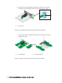
Figure C-43. Removing of PCI Filler on the PCI Riser board assembly....................................................C-33
Figure C-44. Inserting the PCI Card into the PCI Riser board assembly ..................................................C-34
Figure C-45. Closing the PCI Card Locks of the PCI Riser board assembly .............................................C-34
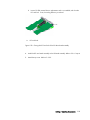
Figure C-46. Putting in the PCI Riser Board Assembly ..........................................................................C-35
Figure C-47. Placing the PCI Riser Board Assembly into Position...........................................................C-35
Figure C-48. Tightening the screw of the PCI Riser board assembly.......................................................C-36
Figure C-49. Closing the Levers of the PCI Riser board assembly ...........................................................C-37
Figure C-50. Opening the PCI Card Lock of the PCI Riser board assembly.............................................C-38
Figure C-51. Removing the PCI Card from the PCI Riser board assembly ................................................C-38
Figure C-52. Closing the PCI Card Lock of the PCI Riser board assembly...............................................C-39
List of Tables
Table 2-1. NovaScale 3025/3045 Drawer front view ........................................................................ 2-5
Table 2-2. Control panel controls...................................................................................................... 2-6
Table 2-3. Control panel LED states................................................................................................... 2-7
Table 2-4. NovaScale 3025/3045 Power supply configurations........................................................ 2-13
Table 2-5. NovaScale 3045 COMPACT Server Features Summary..................................................... 2-17
Table 2-6. Control panel controls.................................................................................................... 2-19
Table 2-7. Control panel LED states................................................................................................. 2-20
Table 2-8. NovaScale 3045 COMPACT Power Supply Configuration................................................. 2-24
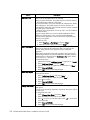
Table 3-1. Boot maintenance menu options........................................................................................ 3-3
Table 3-2. Basic EFI Shell commands................................................................................................. 3-6
Table 3-3. Using Setup screen ........................................................................................................ 3-12
Table 3-4. Primary setup screen...................................................................................................... 3-12
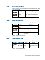
Table 3-5. Processor configuration screen ........................................................................................ 3-13
Table 3-6. Memory configuration screen.......................................................................................... 3-13
Table 3-7. Devices configuration screen........................................................................................... 3-13
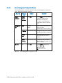
Table 3-8. Server Management configuration screen......................................................................... 3-14
Table 3-9. COM1 Console Redirection configuration screen.............................................................. 3-15
Table 4-1. Basic troubleshooting checklist .......................................................................................... 4-2
Table A-1. Bull NovaScale 3025 Server CPU drawer specifications......................................................A-1
Table A-2. Bull NovaScale 3045 Server CPU drawer specifications......................................................A-2
Table A-3. Bull NovaScale 3045 COMPACT Server CPU drawer specifications .....................................A-3
Table C-1. NovaScale 3025/3045 HDD bay population rules.............................................................C-4

ix
Preface
Intended Readers
This guide is intended for use by the Administrators and Operators of the Bull NovaScale
3005 Series Servers.
Chapter1. Delivery
provides the user with pre-requisites for installing and using the server.
Chapter2. Getting Started
describes server features and how to use them.
Chapter3. Using Configuration Software and Utilities
explains how, as Customer Administrator, you can configure the server to
suit your environment.
Chapter4. Basic Troubleshooting
helps you track down problems.
Appendix A. Server Specifications
outlines general server drawer specifications.
Appendix B. Mounting the Server Drawer in the Cabinet
explains how to install the server drawer in the cabinet
Appendix C. Adding, Removing, Hot-Swapping Components
provides you with instructions on how to install, remove and hot-swap
components such as HDD and PCI cards.
Appendix D. Warning Notices
Highlighting
The following conventions are used in this guide:
Bold Identifies predefined commands, subroutines, keywords, files, structures,
buttons, labels and icons.
Italics Identifies referenced publications, chapters, sections, figures and tables.
< > Identifies parameters to be supplied by the user.

x Bull NovaScale 3005 Series - Installation and User's Guide
Related Publications
NovaScale Site Preparation Guide, 86 A187 EF)
explains how to prepare a Data Processing Center for Bull NovaScale Servers, in
compliance with the standards in force. This guide is intended for use by all personnel and
trade representatives involved in the site preparation process.
Bull 1100 & 1300 Cabinet Installation & Service Guide, 86 A191 EM,
explains how to install and fit out rack cabinets for Bull NovaScale Servers and peripheral
devices.
NOTE:
According to server configuration and version, certain features and functions described in
this guide may not be accessible. Please contact your Bull Sales Representative for sales
information.

xi
Regulatory Specifications and Disclaimers
Declaration of the Manufacturer or Importer
We hereby certify that this product is in compliance with European Union EMC Directive
89/336/EEC, using standards EN55022 (Class A) and EN55024 and Low Voltage
Directive 73/23/EEC, using standard EN60950. The product has been marked with the
CE Mark to illustrate its compliance.
Safety Compliance Statement
- UL 60950 (USA)
- IEC 60950 (International)
- CSA 60950 (Canada)
European Community (EC) Council Directives
This product is in conformity with the protection requirements of the following EC Council
Directives:
Electromagnetic Compatibility
- 89/336/EEC (EN 55022 (1998))
- EN55024 (1998)
- EN61000-3-2 (1995)
- EN61000-3-3 (1995)
Europe
EMC Directive, 89/336/EEC
. EN55022, Class A Limit, Radiated & Conducted Emissions
. EN55024, ITE Specific Immunity Standard
. EN61000-4-2, ESD Immunity (Level 2 Contact Discharge, Level 3 Air
Discharge)
. EN61000-4-3, Radiated Immunity (Level 2)
. EN61000-4-4, Electrical Fast Transient (Level 2)
. EN61000-4-5, AC Surge
. EN61000-4-6, Conducted RF
. EN61000-4-8, Power Frequency Magnetic Fields
. EN61000-4-11, Voltage Dips and Interrupts
. EN61000-3-2, Limit for Harmonic Current Emissions
. EN61000-3-3, Voltage Flicker
Low Voltage
- 73/23/EEC (EN 60950)

xii Bull NovaScale 3005 Series - Installation and User's Guide
EC Conformity
- 93/68/EEC
Telecommunications Terminal Equipment
- 199/5/EC
Neither the provider nor the manufacturer can accept responsibility for any failure to satisfy
the protection requirements resulting from a non–recommended modification of the product.
Compliance with these directives requires:
- An EC declaration of conformity from the manufacturer
- An EC label on the product
- Technical documentation
International Electrotechnical Commission (IEC) Statement
This product has been designed and built to comply with standard IEC 60950.
Federal Communications Commission (FCC) Statement
NOTE:
This equipment has been tested and found to comply with the limits for a Class A digital
device, pursuant to Part 15 of the FCC Rules. These limits are designed to provide
reasonable protection against harmful interference when the equipment is operated in a
commercial environment. This equipment generates, uses, and can radiate radio frequency
energy and, if not installed and used in accordance with the instruction manual, may cause
harmful interference to radio communications. Operation of this equipment in a residential
area is likely to cause harmful interference in which case the user will be required to
correct the interference at its own expense.
Properly shielded and grounded cables and connectors must be used in order to meet FCC
emission limits. Neither the provider nor the manufacturer is responsible for any radio or
television interference caused by using other than recommended cables and connectors or
by unauthorized changes or modifications to this equipment. Unauthorized changes or
modifications could void the user’s authority to operate the equipment.
Any changes or modifications not expressly approved by the grantee of this device could
void the user’s authority to operate the equipment. The customer is responsible for ensuring
compliance of the modified product.

xiii
FCC Declaration of Conformity
This device complies with Part 15 of the FCC Rules. Operation is subject to the following
two conditions: (1) this device may not cause harmful interference, and (2) this device must
accept any interference received, including interference that may cause undesired
operation.
This product is in conformity with the protection requirements of the following standards:
Electrical Compatibility:
- UL 60950
- CSA 60950
Canadian Compliance Statement (Industry Canada)
This Class A digital apparatus meets all requirements of the Canadian Interference Causing
Equipment Regulations.
Cet appareil numérique de la classe A est conforme à la norme NMB-003 du Canada.
This product is in conformity with the protection requirements of the following standards:
Laser Compliance Notice
This product that uses laser technology complies with Class 1 laser requirements.
A CLASS 1 LASER PRODUCT label is located on the laser device.
• Class 1 Laser Product
• Luokan 1 Laserlaite
• Klasse 1 Laser Apparat
• Laser Klasse 1

xiv Bull NovaScale 3005 Series - Installation and User's Guide
Definition of Safety Notices
DANGER:
A Danger notice indicates the presence of a hazard that has the potential of causing death
or serious personal injury.
CAUTION:
A Caution notice indicates the presence of a hazard that has the potential of causing
moderate or minor personal injury.
WARNING:
A Warning notice indicates an action that could cause damage to a program, device,
system, or data.
Electrical Safety
The following safety instructions shall be observed when connecting or disconnecting
devices to the system.
DANGER:
The Customer is responsible for ensuring that the AC electricity supply is compliant with
national and local recommendations, regulations, standards and codes of practice.
An incorrectly wired and grounded electrical outlet may place hazardous voltage on metal
parts of the system or the devices that attach to the system and result in an electrical shock.
It is mandatory to remove power cables from electrical outlets before relocating the system
CAUTION:
This unit has more than one power supply cable. Follow procedures for removal of power
from the system when directed.

xv
Laser Safety Information
The optical drive in this system unit is a classified as a Class 1 level Laser product. The
optical drive has a label that identifies its classification.
The optical drive in this system unit is certified in the U.S. to conform to the requirements of
the Department of Health and Human Services 21 Code of Federal Regulations (DHHS 21
CFR) Subchapter J for Class 1 laser products. Elsewhere, the drive is certified to conform to
the requirements of the International Electro technical Commission (IEC) 60825-1: 2001
and CENELEC EN 60825-1: 1994 for Class 1 laser products.
CAUTION:
Invisible laser radiation when open. Do not stare into beam or view directly with optical
instruments.
Class 1 Laser products are not considered to be hazardous. The optical drive contains
internally a Class 3B gallium-arsenide laser that is nominally 30 mill watts at 830
nanometers. The design incorporates a combination of enclosures, electronics, and
redundant interlocks such that there is no exposure to laser radiation above a Class 1 level
during normal operation, user maintenance, or servicing conditions.
Data Integrity and Verification
WARNING:
Bull NovaScale Servers are designed to reduce the risk of undetected data corruption or
loss. However, if unplanned outages or system failures occur, users are strongly advised to
check the accuracy of the operations performed and the data saved or transmitted by the
system at the time of outage or failure.
Environmental Regulation
This product has been built to comply with the Restriction of Certain Hazardous Substances
(RoHS) Directive 2002/95/EC.

xvi Bull NovaScale 3005 Series - Installation and User's Guide

Delivery 1-1
Chapter 1. Delivery
1.1 General Recommendations
1.1.1 Delivery
Site preparation must be completed by the pre-arranged delivery date. Any delay due to
non-completion of the site by the pre-arranged date will be considered as the Customer’s
responsibility. See the NovaScale Site Preparation Guide 86 A1 87EF.
The server cabinet is delivered 24 hours in advance of the scheduled installation date. On
arrival, the server cabinet must be placed, in its packing, in the Computer Room so that it
reaches the room temperature before powering up (optimum operating temperature = 22°
C
±3° C, hygrometry = 50% ±5%).
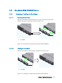
When the server drawer is delivered on its own, follow the procedure described in the
Appendix B.
CAUTION:
It is mandatory for the server cabinet to be transported vertically. The server cabinet is
extremely heavy and requires the use of an elevator. The Data Processing Site manager
must allocate enough personnel to ensure safe handling.

1-2 Bull NovaScale 3005 Series - Installation and User's Guide
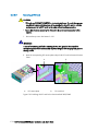
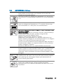
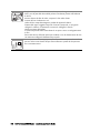
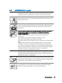
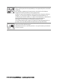
1.1.2 Important Safety Instructions
Before proceeding to install the server, read all caution and safety statements that follow.
CAUTION:
The server can withstand normal levels of environmental ESD . When handling storage
devices, wear an anti-static wrist strap attached to the chassis ground of the server (i.e. any
unpainted metal surface) to prevent them from being damaged by Electrostatic discharge
(ESD).
CAUTION:
Check that the electrical circuit in the vicinity of the system is grounded to earth.
WARNING:
The following instructions are to be complied with for all rack-mounted servers:
Main AC power disconnects:
You are responsible for installing an AC power disconnect for the entire cabinet. This main
disconnect must be readily accessible, and it must be labeled as controlling power to the
entire cabinet and not just to the server(s).
Grounding the cabinet:
To avoid at potential electrical shock hazard, you must provide three-wire safety-grounding
for the cabinet and its contents.
Over current protection:
Each server is designed for an AC line voltage source with up to 20 amperes of over
current protection. If the power system for the cabinet is installed on a branch circuit with
more than 20 amperes of protection, you must provide extra protection for the server.
La pagina si sta caricando...
La pagina si sta caricando...
La pagina si sta caricando...
La pagina si sta caricando...
La pagina si sta caricando...
La pagina si sta caricando...
La pagina si sta caricando...
La pagina si sta caricando...
La pagina si sta caricando...
La pagina si sta caricando...
La pagina si sta caricando...
La pagina si sta caricando...
La pagina si sta caricando...
La pagina si sta caricando...
La pagina si sta caricando...
La pagina si sta caricando...
La pagina si sta caricando...
La pagina si sta caricando...
La pagina si sta caricando...
La pagina si sta caricando...
La pagina si sta caricando...
La pagina si sta caricando...
La pagina si sta caricando...
La pagina si sta caricando...
La pagina si sta caricando...
La pagina si sta caricando...
La pagina si sta caricando...
La pagina si sta caricando...
La pagina si sta caricando...
La pagina si sta caricando...
La pagina si sta caricando...
La pagina si sta caricando...
La pagina si sta caricando...
La pagina si sta caricando...
La pagina si sta caricando...
La pagina si sta caricando...
La pagina si sta caricando...
La pagina si sta caricando...
La pagina si sta caricando...
La pagina si sta caricando...
La pagina si sta caricando...
La pagina si sta caricando...
La pagina si sta caricando...
La pagina si sta caricando...
La pagina si sta caricando...
La pagina si sta caricando...
La pagina si sta caricando...
La pagina si sta caricando...
La pagina si sta caricando...
La pagina si sta caricando...
La pagina si sta caricando...
La pagina si sta caricando...
La pagina si sta caricando...
La pagina si sta caricando...
La pagina si sta caricando...
La pagina si sta caricando...
La pagina si sta caricando...
La pagina si sta caricando...
La pagina si sta caricando...
La pagina si sta caricando...
La pagina si sta caricando...
La pagina si sta caricando...
La pagina si sta caricando...
La pagina si sta caricando...
La pagina si sta caricando...
La pagina si sta caricando...
La pagina si sta caricando...
La pagina si sta caricando...
La pagina si sta caricando...
La pagina si sta caricando...
La pagina si sta caricando...
La pagina si sta caricando...
La pagina si sta caricando...
La pagina si sta caricando...
La pagina si sta caricando...
La pagina si sta caricando...
La pagina si sta caricando...
La pagina si sta caricando...
La pagina si sta caricando...
La pagina si sta caricando...
La pagina si sta caricando...
La pagina si sta caricando...
La pagina si sta caricando...
La pagina si sta caricando...
La pagina si sta caricando...
La pagina si sta caricando...
La pagina si sta caricando...
La pagina si sta caricando...
La pagina si sta caricando...
La pagina si sta caricando...
La pagina si sta caricando...
La pagina si sta caricando...
La pagina si sta caricando...
La pagina si sta caricando...
La pagina si sta caricando...
La pagina si sta caricando...
La pagina si sta caricando...
La pagina si sta caricando...
La pagina si sta caricando...
La pagina si sta caricando...
La pagina si sta caricando...
La pagina si sta caricando...
La pagina si sta caricando...
La pagina si sta caricando...
La pagina si sta caricando...
La pagina si sta caricando...
La pagina si sta caricando...
La pagina si sta caricando...
La pagina si sta caricando...
La pagina si sta caricando...
La pagina si sta caricando...
La pagina si sta caricando...
La pagina si sta caricando...
La pagina si sta caricando...
La pagina si sta caricando...
La pagina si sta caricando...
La pagina si sta caricando...
La pagina si sta caricando...
La pagina si sta caricando...
La pagina si sta caricando...
La pagina si sta caricando...
La pagina si sta caricando...
La pagina si sta caricando...
La pagina si sta caricando...
La pagina si sta caricando...
La pagina si sta caricando...
La pagina si sta caricando...
La pagina si sta caricando...
La pagina si sta caricando...
La pagina si sta caricando...
La pagina si sta caricando...
La pagina si sta caricando...
La pagina si sta caricando...
La pagina si sta caricando...
La pagina si sta caricando...
La pagina si sta caricando...
La pagina si sta caricando...
La pagina si sta caricando...
-
 1
1
-
 2
2
-
 3
3
-
 4
4
-
 5
5
-
 6
6
-
 7
7
-
 8
8
-
 9
9
-
 10
10
-
 11
11
-
 12
12
-
 13
13
-
 14
14
-
 15
15
-
 16
16
-
 17
17
-
 18
18
-
 19
19
-
 20
20
-
 21
21
-
 22
22
-
 23
23
-
 24
24
-
 25
25
-
 26
26
-
 27
27
-
 28
28
-
 29
29
-
 30
30
-
 31
31
-
 32
32
-
 33
33
-
 34
34
-
 35
35
-
 36
36
-
 37
37
-
 38
38
-
 39
39
-
 40
40
-
 41
41
-
 42
42
-
 43
43
-
 44
44
-
 45
45
-
 46
46
-
 47
47
-
 48
48
-
 49
49
-
 50
50
-
 51
51
-
 52
52
-
 53
53
-
 54
54
-
 55
55
-
 56
56
-
 57
57
-
 58
58
-
 59
59
-
 60
60
-
 61
61
-
 62
62
-
 63
63
-
 64
64
-
 65
65
-
 66
66
-
 67
67
-
 68
68
-
 69
69
-
 70
70
-
 71
71
-
 72
72
-
 73
73
-
 74
74
-
 75
75
-
 76
76
-
 77
77
-
 78
78
-
 79
79
-
 80
80
-
 81
81
-
 82
82
-
 83
83
-
 84
84
-
 85
85
-
 86
86
-
 87
87
-
 88
88
-
 89
89
-
 90
90
-
 91
91
-
 92
92
-
 93
93
-
 94
94
-
 95
95
-
 96
96
-
 97
97
-
 98
98
-
 99
99
-
 100
100
-
 101
101
-
 102
102
-
 103
103
-
 104
104
-
 105
105
-
 106
106
-
 107
107
-
 108
108
-
 109
109
-
 110
110
-
 111
111
-
 112
112
-
 113
113
-
 114
114
-
 115
115
-
 116
116
-
 117
117
-
 118
118
-
 119
119
-
 120
120
-
 121
121
-
 122
122
-
 123
123
-
 124
124
-
 125
125
-
 126
126
-
 127
127
-
 128
128
-
 129
129
-
 130
130
-
 131
131
-
 132
132
-
 133
133
-
 134
134
-
 135
135
-
 136
136
-
 137
137
-
 138
138
-
 139
139
-
 140
140
-
 141
141
-
 142
142
-
 143
143
-
 144
144
-
 145
145
-
 146
146
-
 147
147
-
 148
148
-
 149
149
-
 150
150
-
 151
151
-
 152
152
-
 153
153
-
 154
154
-
 155
155
-
 156
156
-
 157
157
-
 158
158


Bull NovaScale 3005 Installation and Guida utente
- Categoria
- Server
- Tipo
- Guida utente
- Questo manuale è adatto anche per
in altre lingue
Documenti correlati
Altri documenti
-
DeLOCK 18206 Scheda dati
-
Intel SRKA4 - Server Platform - 0 MB RAM Manuale utente
-
-
-
NAD D 3045 Manuale utente
-
Vantec MRK-320ST-BK Manuale utente
-
-
Sony RM-VL610T Manuale utente
-
Yamaha HTR-6250 Manuale del proprietario
-
Yamaha RX-V465 Manuale del proprietario