Intel SR1625UR - Server System - 0 MB RAM Manuale utente
- Categoria
- Server barebone
- Tipo
- Manuale utente

Intel
®
Server System SR1625UR
Service Guide
A Guide for Technically Qualified Assemblers of Intel
®
Identified Subassemblies/
Products
Intel Order Number E52881-005

ii Intel
®
Server System SR1625UR Service Guide
Disclaimer
Information in this document is provided in connection with Intel
®
products. No license, express or implied, by
estoppel or otherwise, to any intellectual property rights is granted by this document. Except as provided in Intel's
Terms and Conditions of Sale for such products, Intel assumes no liability whatsoever, and Intel disclaims any
express or implied warranty, relating to sale and/or use of Intel products including liability or warranties relating to
fitness for a particular purpose, merchantability, or infringement of any patent, copyright or other intellectual property
right. Intel products are not designed, intended or authorized for use in any medical, life saving, or life sustaining
applications or for any other application in which the failure of the Intel product could create a situation where
personal injury or death may occur. Intel may make changes to specifications and product descriptions at any time,
without notice.
Intel server boards contain a number of high-density VLSI and power delivery components that need adequate
airflow for cooling. Intel's own chassis are designed and tested to meet the intended thermal requirements of these
components when the fully integrated system is used together. It is the responsibility of the system integrator that
chooses not to use Intel developed server building blocks to consult vendor datasheets and operating parameters to
determine the amount of airflow required for their specific application and environmental conditions. Intel Corporation
can not be held responsible if components fail or the server board does not operate correctly when used outside any
of their published operating or non-operating limits.
Intel, Intel Pentium, and Intel Xeon are trademarks or registered trademarks of Intel Corporation or its subsidiaries in
the United States and other countries.
* Other names and brands may be claimed as the property of others.
Copyright © 2008-2011, Intel Corporation. All Rights Reserved

Intel
®
Server System SR1625UR Service Guide iii
Preface
About this Manual
Thank you for purchasing and using the Intel
®
Server System SR1625UR.
This manual is written for system technicians who are responsible for troubleshooting,
upgrading, and repairing this server system. This document provides reference
information, feature information, and step by step instructions on how to add and replace
components on the server system. For the latest version of this manual, see
http://www.intel.com/p/en_US/support/highlights/server/s5520ur.
Manual Organization
Chapter 1 provides information on the contents of each server system and a list of
reference resources. This includes a list of technical documents that provide additional
details on the Intel
®
Server System SR1625UR, and the location where they can be found.
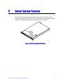
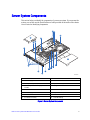
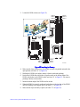
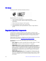
Chapter 2 provides a brief overview of the server system. This includes a list of the server
system features, illustrations of the product, and product diagrams to help you identify
components and their locations.
Chapter 3 provides instructions on adding and replacing components. It provides step-by-
step instructions and diagrams for installing or replacing components such as the fans,
power supply, drives, and other components.
Chapter 4 provides instructions on using the utilities that are shipped with the board or
that may be required to update the system. This includes information for navigating
through the BIOS Setup screens, performing a BIOS update, and resetting the password or
BIOS defaults.
The back of this manual provides technical specifications, regulatory information,
“getting help” information, and the warranty.

iv Intel
®
Server System SR1625UR Service Guide

Intel
®
Server System SR1625UR Service Guide v
Safety Information
Important Safety Instructions
Read all caution and safety statements in this document before performing any of the
instructions. See also Intel Server Boards and Server Chassis Safety Information on the
Intel
®
Server Deployment Toolkit 3.0 CD and/or at
http://www.intel.com/support/motherboards/server/sb/cs-010770.htm.
Wichtige Sicherheitshinweise
Lesen Sie zunächst sämtliche Warn- und Sicherheitshinweise in diesem Dokument, bevor
Sie eine der Anweisungen ausführen. Beachten Sie hierzu auch die Sicherheitshinweise zu
Intel-Serverplatinen und Servergehäusen auf der Intel
®
Server Deployment Toolkit 3.0 CD
oder unter http://www.intel.com/support/motherboards/server/sb/cs-010770.htm.
Consignes de sécurité
Lisez attention toutes les consignes de sécurité et les mises en garde indiquées dans ce
document avant de suivre toute instruction. Consultez Intel Server Boards and Server
Chassis Safety Information sur le Intel
®
Server Deployment Toolkit 3.0 CD ou bien
rendez-vous sur le site
http://www.intel.com/support/motherboards/server/sb/cs-010770.htm.
Instrucciones de seguridad importantes
Lea todas las declaraciones de seguridad y precaución de este documento antes de realizar
cualquiera de las instrucciones. Vea Intel Server Boards and Server Chassis Safety
Information en el Intel
®
Server Deployment Toolkit 3.0 CD y/o en
http://www.intel.com/support/motherboards/server/sb/cs-010770.htm.

vi Intel
®
Server System SR1625UR Service Guide
重要安全指导

Intel
®
Server System SR1625UR Service Guide vii
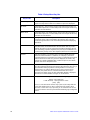
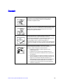
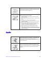
Warnings
Heed safety instructions: Before working with your server product, whether you are
using this guide or any other resource as a reference, pay close attention to the safety
instructions. You must adhere to the assembly instructions in this guide to ensure and
maintain compliance with existing product certifications and approvals. Use only the
described, regulated components specified in this guide. Use of other products/
components will void the UL listing and other regulatory approvals of the product and
will most likely result in noncompliance with product regulations in the region(s) in which
the product is sold.
System power on/off: The power button DOES NOT turn off the system AC power. To
remove power from system, you must unplug the AC power cord from the wall outlet.
Make sure the AC power cord is unplugged before you open the chassis, add, or remove
any components.
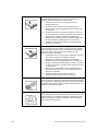
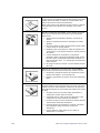
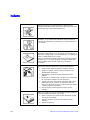
Hazardous conditions, devices and cables: Hazardous electrical conditions may be
present on power, telephone, and communication cables. Turn off the server and
disconnect the power cord, telecommunications systems, networks, and modems attached
to the server before opening it. Otherwise, personal injury or equipment damage can
result.
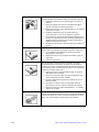
Electrostatic discharge (ESD) and ESD protection: ESD can damage disk drives,
boards, and other parts. We recommend that you perform all procedures in this chapter
only at an ESD workstation. If one is not available, provide some ESD protection by
wearing an antistatic wrist strap attached to chassis ground any unpainted metal surface on
your server when handling parts.
ESD and handling boards: Always handle boards carefully. They can be extremely
sensitive to ESD. Hold boards only by their edges. After removing a board from its
protective wrapper or from the server, place the board component side up on a grounded,
static free surface. Use a conductive foam pad if available but not the board wrapper. Do
not slide board over any surface.
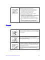
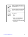
Installing or removing jumpers: A jumper is a small plastic encased conductor that slips
over two jumper pins. Some jumpers have a small tab on top that you can grip with your
fingertips or with a pair of fine needle nosed pliers. If your jumpers do not have such a tab,
take care when using needle nosed pliers to remove or install a jumper; grip the narrow
sides of the jumper with the pliers, never the wide sides. Gripping the wide sides can
damage the contacts inside the jumper, causing intermittent problems with the function
controlled by that jumper. Take care to grip with, but not squeeze, the pliers or other tool
you use to remove a jumper, or you may bend or break the pins on the board.

viii Intel
®
Server System SR1625UR Service Guide

Intel
®
Server System SR1625UR Service Guide ix
Table of Contents
Preface ........................................................................................................................iii
About this Manual ................................................................................................................. iii
Manual Organization ............................................................................................................. iii
Safety Information ......................................................................................................v
Important Safety Instructions .................................................................................................v
Wichtige Sicherheitshinweise ................................................................................................v
Consignes de sécurité ...........................................................................................................v
Instrucciones de seguridad importantes ................................................................................v
Warnings .............................................................................................................................. vii
Chapter 1: Server System Contents and References .............................................1
Server System Contents ........................................................................................................1
Intel
®
Server System SR1625UR Contents ..................................................................1
Intel
®
Server System SR1625URSAS Contents ...........................................................2
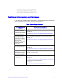
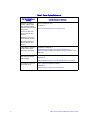
Additional Information and Software ......................................................................................3
Chapter 2: Server System Features ..........................................................................5
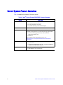
Server System Feature Overview ..........................................................................................6
Server System Components ..................................................................................................9
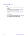
Intel
®
Light-Guided Diagnostics ..................................................................................10
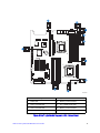
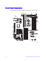
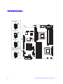
Server Board Components ..................................................................................................14
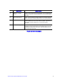
Configuration Jumpers ................................................................................................16
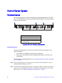
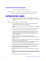
Front of Server System ........................................................................................................18
Peripheral Devices ......................................................................................................18
Control Panel ...............................................................................................................19
Bezels ..........................................................................................................................23
Rear of Server System ........................................................................................................24
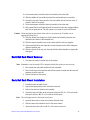
Back Panel Connectors ...............................................................................................25
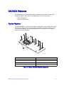
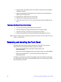
SAS/SATA Midplanes ..........................................................................................................27
Passive Midplane ........................................................................................................27
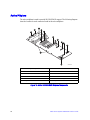
Active Midplane ...........................................................................................................28
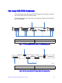
Hot-swap SAS/SATA Backplane .........................................................................................29
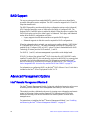
RAID Support .......................................................................................................................30
Advanced Management Options .........................................................................................30
Intel® Remote Management Module 3 ........................................................................30
Rack Mount Options ............................................................................................................31
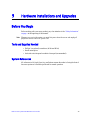
Chapter 3: Hardware Installations and Upgrades .................................................33
Before You Begin .................................................................................................................33
Tools and Supplies Needed ........................................................................................33

x Intel
®
Server System SR1625UR Service Guide
System References ..................................................................................................... 33
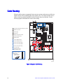
Cable Routing ...................................................................................................................... 34
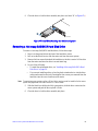
Removing and Installing from a Rack ..................................................................................35
Fixed Bracket Rack Mount Removal ...........................................................................36
Fixed Bracket Rack Mount Installation ........................................................................36
Basic Rail Rack Mount Removal .................................................................................37
Basic Rail Rack Mount Installation ..............................................................................37
Tool-less Rail Rack Mount Servicing ..........................................................................38
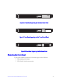
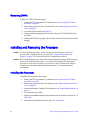
Removing and Installing the Front Bezel .............................................................................38
Removing the Front Bezel ........................................................................................... 39
Installing the Front Bezel ............................................................................................. 40
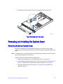
Removing and Installing the System Cover ........................................................................41
Removing the Server System Cover ...........................................................................41
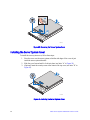
Installing the Server System Cover .............................................................................42
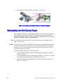
Removing and Installing the PCI Riser Assembly ...............................................................43
Removing the PCI Riser Assembly ............................................................................. 43
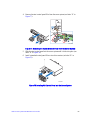
Installing the PCI Riser Assembly ............................................................................... 44
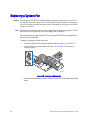
Replacing the PCI Riser Card .............................................................................................45
Removing the PCI Express* Riser Card .....................................................................45
Installing the Replacement PCI Express* Riser Card .................................................46
Installing and Removing a PCI Add-in Card ........................................................................ 46
Installing a PCI Add-in Card ........................................................................................46
Removing a PCI Add-in Card ......................................................................................47
Removing and Installing the Processor Air Duct .................................................................48
Removing the Processor Air Duct ...............................................................................48
Installing the Processor Air Duct .................................................................................49
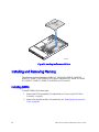
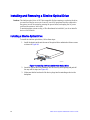
Installing and Removing Memory ........................................................................................50
Installing DIMMs ..........................................................................................................50
Removing DIMMs ........................................................................................................52
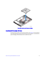
Installing and Removing the Processor ............................................................................... 52
Installing the Processor ............................................................................................... 52
Installing the Heatsink .................................................................................................55
Removing the Heatsink ...............................................................................................57
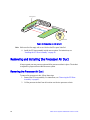
Removing the Processor ............................................................................................. 58
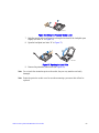
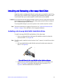
Installing and Removing a Hot-swap Hard Drive ................................................................. 59
Installing a Hot-swap SAS/SATA Hard Disk Drive ...................................................... 59
Removing a Hot-swap SAS/SATA Hard Disk Drive .................................................... 61
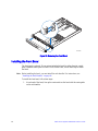
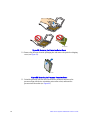
Installing and Removing a Slimline Optical Drive ................................................................62
Installing a Slimline Optical Drive ................................................................................62
Removing a Slimline Optical Drive ..............................................................................63
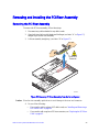
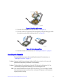
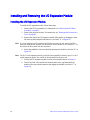
Installing and Removing the I/O Expansion Module ............................................................64
Installing the I/O Expansion Module ............................................................................64
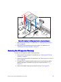
Removing the I/O Expansion Module(s) .....................................................................65
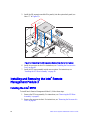
Installing and Removing the Intel
®
Remote Management Module 3 ...................................66

Intel
®
Server System SR1625UR Service Guide xi
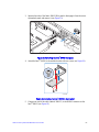
Installing the Intel
®
RMM3 ...........................................................................................66
Removing the Intel
®
RMM3 .........................................................................................69
Removing and Installing the Midplane Board ......................................................................70
Removing the Midplane Board ....................................................................................70
Installing the Midplane Board ......................................................................................71
Installing and Removing the Intel
®
Integrated RAID Activation Key and the RAID Mini DIMM
(Active System Only) ...................................................................................................74
Installing the Intel
®
Integrated RAID Activation Key and the RAID Mini-DIMM ...........74
Removing the Intel
®
Integrated RAID Activation Key and the RAID Mini-DIMM .........75
Installing and Removing the RAID Battery Backup Unit (Active System Only) ...................76
Installing the RAID Battery Backup Unit (BBU) ...........................................................76
Removing the RAID Battery Backup Unit ....................................................................77
Removing and Installing the Server Board ..........................................................................78
Removing the Server Board ........................................................................................78
Installing the Server Board ..........................................................................................79
Replacing the Backup Battery .............................................................................................81
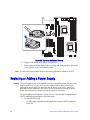
Replacing or Adding a Power Supply ..................................................................................82
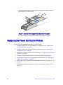
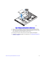
Replacing the Power Distribution Module ............................................................................84
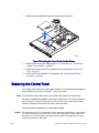
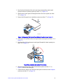
Replacing the Control Panel ................................................................................................86
Reinstalling the Mini Control Panel ......................................................................................88
Replacing a System Fan ......................................................................................................90
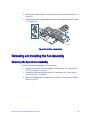
Removing and Installing the Fan Assembly .........................................................................91
Removing the System Fan Assembly ..........................................................................91
Installing the System Fan Assembly ............................................................................92
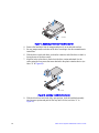
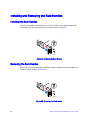
Installing and Removing the Rack Handles .........................................................................94
Installing the Rack Handles .........................................................................................94
Removing the Rack Handles .......................................................................................94
Chapter 4: Server Utilities ........................................................................................95
Using the BIOS Setup Utility ................................................................................................95
Entering BIOS Setup ...................................................................................................95
If You Cannot Access Setup ........................................................................................95
Setup Menus ...............................................................................................................95
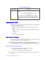
Upgrading the BIOS .............................................................................................................97
Preparing for the Upgrade ...........................................................................................97
Upgrading the BIOS ....................................................................................................98
Clearing the Password .........................................................................................................98
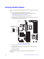
Restoring the BIOS Defaults ..............................................................................................100
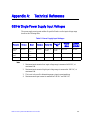
Appendix A: Technical Reference ........................................................................101
650-W Single Power Supply Input Voltages ......................................................................101
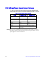
650-W Single Power Supply Output Voltages ...................................................................102
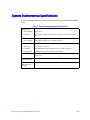
System Environmental Specifications ................................................................................103
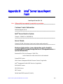
Appendix B: Intel
®
Server Issue Report Form .....................................................105

xii Intel
®
Server System SR1625UR Service Guide
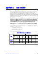
Appendix C: LED Decoder .....................................................................................111
Appendix D: Getting Help ......................................................................................119
Warranty Information .........................................................................................................119
Appendix E: Regulatory and Certification Information .......................................121
Product Regulatory Compliance ........................................................................................121
Product Safety Compliance ....................................................................................... 121
Product EMC Compliance - Class A Compliance .....................................................122
Product Ecology Compliance ....................................................................................123
Certifications/Registrations/Declarations .................................................................. 123
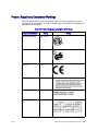
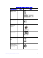
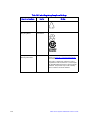
Product Regulatory Compliance Markings ................................................................124
Rack Mount Installation Guidelines ...................................................................................128
Power Cord Usage Guidelines ..........................................................................................129
Electromagnetic Compatibility Notices .............................................................................. 130
FCC Verification Statement (USA) ............................................................................130
ICES-003 (Canada) ...................................................................................................131
CE Declaration of Conformity (Europe) .....................................................................131
VCCI (Japan) ............................................................................................................131
BSMI (Taiwan) ..........................................................................................................131
KCC (Korea) ..............................................................................................................132
Regulated Specified Components .....................................................................................132
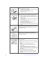
Appendix F: Installation/Assembly Safety Instructions ......................................133
English ...............................................................................................................................133
Deutsch ............................................................................................................................. 135
Français ............................................................................................................................. 137
Español .............................................................................................................................139
Italiano ...............................................................................................................................142
Appendix G: Safety Information ............................................................................145
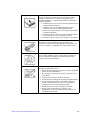
English ...............................................................................................................................145
Server Safety Information ......................................................................................... 145
Safety Warnings and Cautions .................................................................................. 145
Intended Application Uses ........................................................................................ 146
Site Selection ............................................................................................................146
Equipment Handling Practices ..................................................................................146
Power and Electrical Warnings ................................................................................. 147
System Access Warnings ......................................................................................... 148
Rack Mount Warnings ...............................................................................................148
Electrostatic Discharge (ESD) ................................................................................... 149
Other Hazards ........................................................................................................... 149
Deutsch ............................................................................................................................. 150
Sicherheitshinweise für den Server ...........................................................................150
Sicherheitshinweise und Vorsichtsmaßnahmen .......................................................150
Zielbenutzer der Anwendung .................................................................................... 151

Intel
®
Server System SR1625UR Service Guide xiii
Standortauswahl ........................................................................................................151
Handhabung von Geräten .........................................................................................151
Warnungen zu Netzspannung und Elektrizität ..........................................................152
Warnhinweise für den Systemzugang .......................................................................153
Warnhinweise für Racks ............................................................................................153
Elektrostatische Entladungen (ESD) .........................................................................154
Andere Gefahren .......................................................................................................154
Français .............................................................................................................................155
Consignes de securite sur le serveur ........................................................................155
Séurité: avertissements et mises en garde ...............................................................155
Domaines d’utilisation prévus ....................................................................................156
Sélection d’un emplacement .....................................................................................156
Pratiques de manipulation de l’équipement ...............................................................157
Alimentation et avertissements en matiére d’électricité .............................................157
Avertissements sur le cordon d’alimentation .............................................................158
Avertissements sur l’accés au systéme .....................................................................158
Avertissements sur le montage en rack ....................................................................159
Décharges électrostatiques (ESD) ............................................................................160
Autres risques ............................................................................................................160
Périphériques laser ....................................................................................................161
Español ..............................................................................................................................161
Información de seguridad del servidor ......................................................................161
Advertencias y precauciones sobre seguridad ..........................................................161
Aplicaciones y usos previstos ....................................................................................162
Seleccién de la ubicación ..........................................................................................162
Manipulacién del equipo ............................................................................................163
Advertencias de alimentacién y eléctricas .................................................................163
Advertencias sobre el cable de alimentación ............................................................163
Advertencias el acceso al sistema ............................................................................164
Advertencias sobre el montaje en bastidor ...............................................................165
Descarga electrostática (ESD) ..................................................................................165
Otros riesgos .............................................................................................................166

xiv Intel
®
Server System SR1625UR Service Guide

Intel
®
Server System SR1625UR Service Guide xv
List of Figures
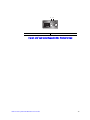
Figure 1. Intel
®
Server System SR1625UR............................................................................... 5
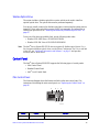
Figure 2. Server System Components...................................................................................... 9
Figure 3. Intel
®
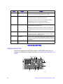
Light-Guided Diagnostic LEDs - Server Board............................................... 11
Figure 4. Intel
®
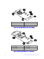
Light-Guided Diagnostic LEDs - Passive Midplane........................................ 12
Figure 5. Intel
®
Light-Guided Diagnostic LEDs - Active Midplane .......................................... 12
Figure 6. Intel
®
Light-Guided Diagnostic LEDs - Mini Control Panel ...................................... 13
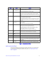
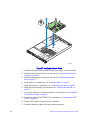
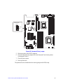
Figure 7. Server Board Connector and Component Locations ............................................... 15
Figure 8. Configuration Jumpers............................................................................................. 17
Figure 9. Front Panel Features and Peripherals..................................................................... 18
Figure 10. Mini Control Panel.................................................................................................. 20
Figure 11. Standard Control Panel.......................................................................................... 21
Figure 12. Intel
®
Local Control Panel...................................................................................... 23
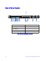
Figure 13. Server System Rear Components ......................................................................... 24
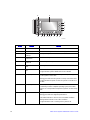
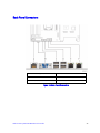
Figure 14. Back Panel Connectors.......................................................................................... 25
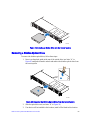
Figure 15. Passive SATA/SAS Midplane Components........................................................... 27
Figure 16. Active SAS/SAS RAID Midplane Components ...................................................... 28
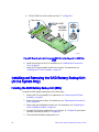
Figure 17. Hot-swap SAS/SATA Backplane Front Side Components..................................... 29
Figure 18. Hot-swap SAS/SATA Backplane Back Side Components..................................... 29
Figure 19. System Cable Routing ........................................................................................... 34
Figure 20. Front Bezel Supporting the Standard Control Panel.............................................. 39
Figure 21. Front Bezel Supporting the Intel
®
Local Control Panel.......................................... 39
Figure 22. Front Bezel Supporting the Mini Control Panel...................................................... 39
Figure 23. Removing the Front Bezel...................................................................................... 40
Figure 24. Installing the Front Bezel........................................................................................ 41
Figure 25. Removing the Server System Cover...................................................................... 42
Figure 26. Installing the Server System Cover........................................................................ 42
Figure 27. Removing PCI Riser Assembly from the Server System....................................... 43
Figure 28. Installing PCI Riser Assembly into the Server System........................................... 44
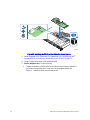
Figure 29. Removing the PCI Express* Riser Card ................................................................ 45
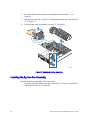
Figure 30. Installing the Replacement PCI Express* Riser Card............................................ 46
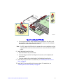
Figure 31. Installing an Add-In Card........................................................................................ 47
Figure 32. Removing an Add-In Card...................................................................................... 48
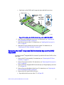
Figure 33. Removing the Processor Air Duct.......................................................................... 49
Figure 34. Installing the Processor Air Duct............................................................................ 50
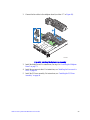
Figure 35. Installing the Memory............................................................................................. 51
Figure 36. Lifting the Processor Socket Lever ........................................................................ 53
Figure 37. Opening the Load Plate ......................................................................................... 53
Figure 38. Removing the Protective Socket Cover ................................................................. 54
Figure 39. Removing the Processor Protective Cover............................................................ 54
Figure 40. Installing the Processor.......................................................................................... 55
Figure 41. Closing the Load Plate........................................................................................... 55
Figure 42. Installing the Heatsink............................................................................................ 56

xvi Intel
®
Server System SR1625UR Service Guide
Figure 43. Removing the Heatsink.......................................................................................... 58
Figure 44. Removing Hot-swap Disk Carrier from the Server System.................................... 59
Figure 45. Removing Drive Blank from Drive Carrier.............................................................. 60
Figure 46. Installing Hard Drive into Carrier............................................................................ 60
Figure 47. Install Drive Assemby into the Server System....................................................... 61
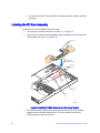
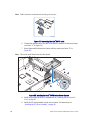
Figure 48. Installing the Plastic Guide to the Optical Drive..................................................... 62
Figure 49. Installing an Optical Drive into the Server System................................................. 63
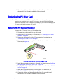
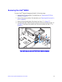
Figure 50. Removing the Slimline Optical Drive from the Server System............................... 63
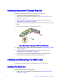
Figure 51. Installing the I/O Expansion Module to the Server System.................................... 65
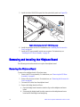
Figure 52. Removing the I/O Expansion Module from the Server System ............................. 66
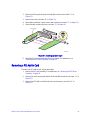
Figure 53. Removing the Intel
®
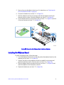
RMM3 filler panel.................................................................. 67
Figure 54. Installing the Intel
®
RMM3 to the bracket.............................................................. 67
Figure 55. Connecting the Intel
®
RMM3 cable ....................................................................... 68
Figure 56. Installing the Intel
®
RMM3 to the Server System .................................................. 68
Figure 57. Removing the Intel
®
RMM3 from the Server System............................................ 69
Figure 58. Installing the Intel
®
RMM3 filler panel.................................................................... 70
Figure 59. Removing the Midplane from the Server System.................................................. 71
Figure 60. Installing the Midplane Board into the Server System........................................... 72
Figure 61. Installing the SATA Cables.................................................................................... 73
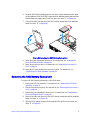
Figure 62. Installing the RAID Activation Key and the RAID Mini-DIMM................................ 75
Figure 63. Removing the Intel
®
Integrated RAID Activation Key and the RAID Mini-DIMM... 76
Figure 64. Installing the RAID Battery Backup Unit................................................................ 77
Figure 65. Removing the RAID Battery Backup Unit.............................................................. 78
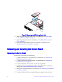
Figure 66. Removing the Server Board .................................................................................. 79
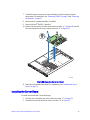
Figure 67. Installing the Server Board .................................................................................... 80
Figure 68. Replacing the Backup Battery ............................................................................... 82
Figure 69. Removing Power Supply Filler Panel from the Server System.............................. 83
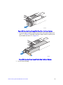
Figure 70. Removing Power Supply Module from the Server System.................................... 83
Figure 71. Installing Power Supply Module into the Server System....................................... 84
Figure 72. Removing the Power Distribution Board Cover..................................................... 85
Figure 73. Installing the Power Distribution Board Cover....................................................... 86
Figure 74. Removing Mini Control Panel Module from the Server System............................. 87
Figure 75. Connecting the Control Panel Cables.................................................................... 87
Figure 76. Installing Control Panel Module into the Server System........................................ 88
Figure 77. Removing the Standard Control Panel from the Server System ........................... 89
Figure 78. Installing Mini Control Panel into the Server System............................................. 89
Figure 79. Removing a System Fan ....................................................................................... 90
Figure 80. Installing a System Fan ......................................................................................... 91
Figure 81. Removing the Fan Assembly................................................................................. 92
Figure 82. Installing the System Fan Assembly...................................................................... 93
Figure 83. Installing the Rack Handle..................................................................................... 94
Figure 84. Removing the Rack Handle................................................................................... 94
Figure 85. Password Clear Jumper ........................................................................................ 99
Figure 86. BIOS Default Jumper........................................................................................... 100
Figure 87. Diagnostic LED Placement Diagram ................................................................... 114

Intel
®
Server System SR1625UR Service Guide xvii
List of Tables
Table 1. Server System References .........................................................................................3
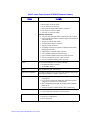
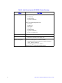
Table 2. Intel
®
Server System SR1625UR Feature Summary ..................................................6
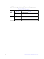
Table 3. NIC LED Descriptions ...............................................................................................26
Table 4. Setup Menu Key Use ................................................................................................95
Table 5. Power Supply input Voltages ..................................................................................103
Table 6. Power Supply Output Capability ..............................................................................104
Table 7. System Environmental Specifications .....................................................................105
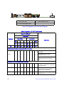
Table 8. POST Progress Code LED Example .......................................................................113
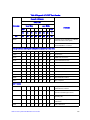
Table 9. Diagnostic LED POST Code Decoder .....................................................................114
Table 10. Product Regulatory Compliance Markings ............................................................126

xviii Intel
®
Server System SR1625UR Service Guide

Intel
®
Server System SR1625UR Service Guide 1
1 Server System Contents and
References
There are two versions of the Intel
®
Server System SR1625UR:
• Intel
®
Server System SR1625UR (Passive system)
• Intel
®
Server System SR1625URSAS (Active system)
Unless noted otherwise, all references to the Intel
®
Server System SR1625UR refer to
both product codes.
Server System Contents
The Intel
®
Server System SR1625UR ships with the Intel
®
Server Board S5520UR. For
information about the server board, see Intel
®
Server Board S5520UR Technical Product
Specification.
The contents of each server system are listed below.
Intel
®
Server System SR1625UR Contents
Your Intel
®
Server System SR1625UR (passive system) ships with the following items:
• Intel
®
Server Board S5520UR, installed in the server system
• One 650-W power supply, installed in the server system
• Full-length and full-height PCI Express* riser card assembly, installed in the server
system
• Processor air duct, installed in the server system
• Two processor heatsinks, installed in the server system
• Passive midplane, installed in the server system
• Hot-swap SAS/SATA backplane, installed in the server system
• Bridge board, installed in the server system
• Mini control panel, installed in the server system
• Six 2.5-inch hot-swap drive trays and drive filler blanks, installed in the server
system
• A filler panel (for drive locations 6 and 7), installed in the server system
• System fan assembly, including five 40X40X56-mm dual-rotor fans, installed in the
server system

2 Intel
®
Server System SR1625UR Service Guide
• A box of hardware components (referred to herein as the “hardware box”)
• Optical drive tray assembly, in the hardware box
• Two screws for installing the optical drive component, in the hardware box
• Rack handles, in the hardware box
• Slimline peripheral bay filler panel, in the hardware box
• One ganged SATA cable (consisting of six cables tied together), in the hardware box
• Attention document, in the server system product box
• Quick Start User's Guide, in the server system product box
• Intel
®
Server Deployment Toolkit 3.0 CD
• Intel
®
System Management Software DVD
Intel
®
Server System SR1625URSAS Contents
Your Intel
®
Server System SR1625URSAS (active system) ships with the following
items:
• Intel
®
Server Board S5520UR, installed in the server system
• One 650-W power supply, installed in the server system
• Full-length and full-height PCI Express* riser card assembly, installed in the server
system
• Processor air duct, installed in the server system
• Two processor heatsinks, installed in the server system
• Active SAS/SATA midplane, installed in the server system
• Hot-swap SAS/SATA backplane, installed in the server system
• Bridge board, installed in the server system
• Mini control panel, installed in the server system
• Eight 2.5-inch hot-swap drive trays and drive filler blanks, installed in the server
system
• System fan assembly, including five 40X40X56-mm dual-rotor fans, installed in the
server system
• A box of hardware components (referred to herein as the “hardware box”)
• Optical drive tray assembly, in the hardware box
• Two screws for installing the optical drive component, in the hardware box
• Slimline peripheral bay filler panel, in the hardware box
• Rack handles, in the hardware box
• Attention document, in the server system product box
• Quick Start User's Guide, in the server system product box
La pagina sta caricando ...
La pagina sta caricando ...
La pagina sta caricando ...
La pagina sta caricando ...
La pagina sta caricando ...
La pagina sta caricando ...
La pagina sta caricando ...
La pagina sta caricando ...
La pagina sta caricando ...
La pagina sta caricando ...
La pagina sta caricando ...
La pagina sta caricando ...
La pagina sta caricando ...
La pagina sta caricando ...
La pagina sta caricando ...
La pagina sta caricando ...
La pagina sta caricando ...
La pagina sta caricando ...
La pagina sta caricando ...
La pagina sta caricando ...
La pagina sta caricando ...
La pagina sta caricando ...
La pagina sta caricando ...
La pagina sta caricando ...
La pagina sta caricando ...
La pagina sta caricando ...
La pagina sta caricando ...
La pagina sta caricando ...
La pagina sta caricando ...
La pagina sta caricando ...
La pagina sta caricando ...
La pagina sta caricando ...
La pagina sta caricando ...
La pagina sta caricando ...
La pagina sta caricando ...
La pagina sta caricando ...
La pagina sta caricando ...
La pagina sta caricando ...
La pagina sta caricando ...
La pagina sta caricando ...
La pagina sta caricando ...
La pagina sta caricando ...
La pagina sta caricando ...
La pagina sta caricando ...
La pagina sta caricando ...
La pagina sta caricando ...
La pagina sta caricando ...
La pagina sta caricando ...
La pagina sta caricando ...
La pagina sta caricando ...
La pagina sta caricando ...
La pagina sta caricando ...
La pagina sta caricando ...
La pagina sta caricando ...
La pagina sta caricando ...
La pagina sta caricando ...
La pagina sta caricando ...
La pagina sta caricando ...
La pagina sta caricando ...
La pagina sta caricando ...
La pagina sta caricando ...
La pagina sta caricando ...
La pagina sta caricando ...
La pagina sta caricando ...
La pagina sta caricando ...
La pagina sta caricando ...
La pagina sta caricando ...
La pagina sta caricando ...
La pagina sta caricando ...
La pagina sta caricando ...
La pagina sta caricando ...
La pagina sta caricando ...
La pagina sta caricando ...
La pagina sta caricando ...
La pagina sta caricando ...
La pagina sta caricando ...
La pagina sta caricando ...
La pagina sta caricando ...
La pagina sta caricando ...
La pagina sta caricando ...
La pagina sta caricando ...
La pagina sta caricando ...
La pagina sta caricando ...
La pagina sta caricando ...
La pagina sta caricando ...
La pagina sta caricando ...
La pagina sta caricando ...
La pagina sta caricando ...
La pagina sta caricando ...
La pagina sta caricando ...
La pagina sta caricando ...
La pagina sta caricando ...
La pagina sta caricando ...
La pagina sta caricando ...
La pagina sta caricando ...
La pagina sta caricando ...
La pagina sta caricando ...
La pagina sta caricando ...
La pagina sta caricando ...
La pagina sta caricando ...
La pagina sta caricando ...
La pagina sta caricando ...
La pagina sta caricando ...
La pagina sta caricando ...
La pagina sta caricando ...
La pagina sta caricando ...
La pagina sta caricando ...
La pagina sta caricando ...
La pagina sta caricando ...
La pagina sta caricando ...
La pagina sta caricando ...
La pagina sta caricando ...
La pagina sta caricando ...
La pagina sta caricando ...
La pagina sta caricando ...
La pagina sta caricando ...
La pagina sta caricando ...
La pagina sta caricando ...
La pagina sta caricando ...
La pagina sta caricando ...
La pagina sta caricando ...
La pagina sta caricando ...
La pagina sta caricando ...
La pagina sta caricando ...
La pagina sta caricando ...
La pagina sta caricando ...
La pagina sta caricando ...
La pagina sta caricando ...
La pagina sta caricando ...
La pagina sta caricando ...
La pagina sta caricando ...
La pagina sta caricando ...
La pagina sta caricando ...
La pagina sta caricando ...
La pagina sta caricando ...
La pagina sta caricando ...
La pagina sta caricando ...
La pagina sta caricando ...
La pagina sta caricando ...
La pagina sta caricando ...
La pagina sta caricando ...
La pagina sta caricando ...
La pagina sta caricando ...
La pagina sta caricando ...
La pagina sta caricando ...
La pagina sta caricando ...
La pagina sta caricando ...
La pagina sta caricando ...
La pagina sta caricando ...
La pagina sta caricando ...
La pagina sta caricando ...
La pagina sta caricando ...
La pagina sta caricando ...
La pagina sta caricando ...
La pagina sta caricando ...
La pagina sta caricando ...
La pagina sta caricando ...
La pagina sta caricando ...
La pagina sta caricando ...
La pagina sta caricando ...
La pagina sta caricando ...
La pagina sta caricando ...
La pagina sta caricando ...
La pagina sta caricando ...
La pagina sta caricando ...
La pagina sta caricando ...
-
 1
1
-
 2
2
-
 3
3
-
 4
4
-
 5
5
-
 6
6
-
 7
7
-
 8
8
-
 9
9
-
 10
10
-
 11
11
-
 12
12
-
 13
13
-
 14
14
-
 15
15
-
 16
16
-
 17
17
-
 18
18
-
 19
19
-
 20
20
-
 21
21
-
 22
22
-
 23
23
-
 24
24
-
 25
25
-
 26
26
-
 27
27
-
 28
28
-
 29
29
-
 30
30
-
 31
31
-
 32
32
-
 33
33
-
 34
34
-
 35
35
-
 36
36
-
 37
37
-
 38
38
-
 39
39
-
 40
40
-
 41
41
-
 42
42
-
 43
43
-
 44
44
-
 45
45
-
 46
46
-
 47
47
-
 48
48
-
 49
49
-
 50
50
-
 51
51
-
 52
52
-
 53
53
-
 54
54
-
 55
55
-
 56
56
-
 57
57
-
 58
58
-
 59
59
-
 60
60
-
 61
61
-
 62
62
-
 63
63
-
 64
64
-
 65
65
-
 66
66
-
 67
67
-
 68
68
-
 69
69
-
 70
70
-
 71
71
-
 72
72
-
 73
73
-
 74
74
-
 75
75
-
 76
76
-
 77
77
-
 78
78
-
 79
79
-
 80
80
-
 81
81
-
 82
82
-
 83
83
-
 84
84
-
 85
85
-
 86
86
-
 87
87
-
 88
88
-
 89
89
-
 90
90
-
 91
91
-
 92
92
-
 93
93
-
 94
94
-
 95
95
-
 96
96
-
 97
97
-
 98
98
-
 99
99
-
 100
100
-
 101
101
-
 102
102
-
 103
103
-
 104
104
-
 105
105
-
 106
106
-
 107
107
-
 108
108
-
 109
109
-
 110
110
-
 111
111
-
 112
112
-
 113
113
-
 114
114
-
 115
115
-
 116
116
-
 117
117
-
 118
118
-
 119
119
-
 120
120
-
 121
121
-
 122
122
-
 123
123
-
 124
124
-
 125
125
-
 126
126
-
 127
127
-
 128
128
-
 129
129
-
 130
130
-
 131
131
-
 132
132
-
 133
133
-
 134
134
-
 135
135
-
 136
136
-
 137
137
-
 138
138
-
 139
139
-
 140
140
-
 141
141
-
 142
142
-
 143
143
-
 144
144
-
 145
145
-
 146
146
-
 147
147
-
 148
148
-
 149
149
-
 150
150
-
 151
151
-
 152
152
-
 153
153
-
 154
154
-
 155
155
-
 156
156
-
 157
157
-
 158
158
-
 159
159
-
 160
160
-
 161
161
-
 162
162
-
 163
163
-
 164
164
-
 165
165
-
 166
166
-
 167
167
-
 168
168
-
 169
169
-
 170
170
-
 171
171
-
 172
172
-
 173
173
-
 174
174
-
 175
175
-
 176
176
-
 177
177
-
 178
178
-
 179
179
-
 180
180
-
 181
181
-
 182
182
-
 183
183
-
 184
184
-
 185
185
-
 186
186


Intel SR1625UR - Server System - 0 MB RAM Manuale utente
- Categoria
- Server barebone
- Tipo
- Manuale utente
in altre lingue
Documenti correlati
Altri documenti
-
Symantec NetBackup 5220 Hardware Troubleshooting Manual
-
IBM 8688 Manuale utente
-
HP ProLiant DL120 G6 Manuale utente
-
Bull NovaScale 3005 Installation and Guida utente
-
-
Tyan YR188-B537M Manuale utente
-
HP (Hewlett-Packard) Server 633407-001 Manuale utente
-
Acer SO.DVDR1.603 Scheda dati
-
-