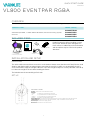
Vari-Lite VL800 EVENTPAR, RGBA Guida Rapida
- Categoria
- Stroboscopi
- Tipo
- Guida Rapida
Questo manuale è adatto anche per

1
QUICK START GUIDE
VL800 EVENTPAR RGBA
912400575002
OVERVIEW
This document provides installation and operation instructions for the following product(s):
PRODUCT NAME ORDER CODE(S)
VL800 Eventpar RGBA, 1 x 200W 3000K LED PAR 64, manual zoom setting w/power
connector
912400575002
912400576323
912400576325
912400576324
INCLUDED ITEMS
POWER CONNECTOR
VL800 Eventpar RGBA
QUICK START GUIDE
(this document)
WARRANTY CARD
OMEGA CLAMP
INSTALLATION AND SETUP
MOUNTING
The unit should be mounted via its screw holes on the bracket. Always ensure that the unit is firmly fixed to avoid
vibration and slipping while operating. Always ensure that the structure to which you are attaching the unit is
secure and is able to support a weight of 10 times of the unit’s weight. Always use a safety cable that can hold up
to 12 times the weight of the unit when installing the fixture.
The luminaire must be mounted by professionals.
SET UP
Read all instructions before installing or using
this product. Retain this quick start guide for
future reference. Additional product information
and descriptions may be found on the product
data sheet.
1 Display. Shows menu and selected functions
2 Buttons.
MENU To select the programming functions
UP To go backward in the selected functions
DOWN To go forward in the selected functions
ENTER To confirm the selected functions
3 DMX/RDM input.
Connectors for DMX 512 operation, 5-pin XLR cable to link the DMX console
4 DMX/RDM thru. Connectors for DMX 512 operation, 5-pin XLR cable to link the next unit
5 Power Input. Connects to supply power.
6 Power Thru. Connects to the next fixture.
CONTROL PANEL

2
QUICK START GUIDE
VL800 EVENTPAR RGBA
912400575002
WARNINGS AND NOTICES
When using electrical equipment, basic safety precautions should always be followed including the following:
• For indoor, dry locations use only. Do not use outdoors.
• Do not mount near gas or electric heaters.
• Equipment should be mounted in locations and at heights where it will not readily be subjected to
tampering by unauthorized personnel.
• The use of accessory equipment not recommended by the manufacturer may cause an unsafe condition
and void warranty.
• Not for residential use. Do not use this equipment for other than intended use.
©2021 Signify Holding. All rights reserved.
All trademarks are owned by Signify Holding or their respective owners. The
information provided herein is subject to change, without notice. Signify does
not give any representation or warranty as to the accuracy or completeness of
the information included herein and shall not be liable for any action in reliance
thereon. The information presented in this document is not intended as any
commercial offer and does not form part of any quotation or contract, unless
otherwise agreed by Signify. Data subject to change.
CUSTOMER SERVICE
If you have any questions regarding this product,
please contact Customer Service by phone at
+1 214-647-7880 or by email at entertainment.
service@signify.com.
C
US
CM
2
SAFETY WARNINGS AND NOTICES
When using electrical equipment, basic safety precautions should
always be followed including the following:
READ AND FOLLOW ALL SAFETY INSTRUCTIONS.
Rated for IP 24 conditions: Protected from water spray from any
direction.
Equipment should be mounted in locations and at heights where it
will not readily be subjected to tampering by unauthorized person-
nel.
The use of accessory equipment not recommended by the manufac-
turer may cause an unsafe condition.
Not for residential use. Do not use this equipment for other than
intended use.
Refer service to qualified personnel. This fixture contains no user
serviceable parts.
Prior to first use, carefully inspect unit for damage from shipping.
Installation and operation to be performed by qualified personnel
only.
Use safety tether when mounting.
Install only in locations with adequate ventilation of at least 50cm
clearance from adjacent surfaces.
Note distance requirement(s) from combustible materials or illumi-
nated objects. Do not mount near gas or electric heaters.
Ensure that ventilation slots are not blocked.
Ensure that the voltage and frequency of the power supply match
the power requirements of the fixture.
The fixture must be earthed/grounded to the appropriate conductor.
Do not operate fixture outside the ambient temperature range of
-5 to 45°C.
Do not connect the fixture to any dimmer pack.
New fixtures may emit a chemical odor due to the manufacturing
process. This odor will dissipate over time.
Prior to each use, carefully inspect power cables and replace any
damaged cables.
Exterior surfaces of the fixture are hot during operation. Take appro-
priate precautions.
Power down the fixture when not in use. Continuous use of the
fixture may shorten the lifespan.
Clean fixture regularly, particularly when working in a dusty environ-
ment.
Never touch power cables or wires while the fixture is powered on.
Avoid entangling power wires with other cables.
In the event of a serious operating problem, immediately discontinue
using the fixture.
Never turn on and o the unit time after time.
The housing, lenses, and/or the ultraviolet filter must be replaced if
they are damaged.
Disconnect mains power if the fixture is not used for a long time.
Original packing materials can be reused for transporting the fixture.
Do not look directly at the light beam while the fixture is on.
SAVE THESE INSTRUCTIONS.
WARNING: Refer to National Electrical Code® and local codes for
cable specifications. Failure to use proper cable can result in damage
to equipment or danger to personnel.
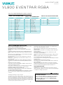
QUICK REFERENCE DMX MAPS
TABLE 1. 16-BIT CHANNEL MODE
CHANNEL PARAMETER
1 Intensity high
2 Intensity low
3 Red high
4 Red low
5 Green high
6 Green low
7 Blue high
8 Blue low
9 Amber high
10 Amber low
11 Color preset
12 Strobe speed
13 Strobe control
14 Control channel
TABLE 2. 8-BIT CHANNEL MODE
CHANNEL PARAMETER
1 Intensity high
2 Red high
3 Green high
4 Blue high
5 Amber high
6 Color preset
7 Strobe speed
8 Strobe control
9 Control channel
TABLE 3. 8-BIT COLOR CHANNEL MODE
CHANNEL PARAMETER
1 Red
2 Green
3 Blue
4 Amber
-
 1
1
-
 2
2


Vari-Lite VL800 EVENTPAR, RGBA Guida Rapida
- Categoria
- Stroboscopi
- Tipo
- Guida Rapida
- Questo manuale è adatto anche per
in altre lingue
Documenti correlati
Altri documenti
-
Elation COLOUR CHORUS Series Manuale utente
-
 DTS NICK NRG 501 Manuale utente
-
 DTS NICK NRG 501 Manuale utente
-
 DTS F-25 Manuale utente
-
 DTS NICK NRG 1201 Manuale utente
-
 DTS Nick Wash 600 Manuale utente
-
Cameo Studio PAR 18 x 8W RGBA Manuale utente
-
ProLights LUMIPIX16H Manuale utente
-
 DTS Delta 8 Full Colour R Manuale utente


