Ubiquiti UAP-Outdoor 5G Manuale utente
- Categoria
- Punti di accesso WLAN
- Tipo
- Manuale utente
Questo manuale è adatto anche per

Outdoor WiFi System
Models: UAP-Outdoor/UAP-Outdoor 5G

i
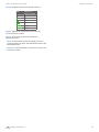
Table of ContentsUniFi
™
AP-Outdoor User Guide
Ubiquiti Networks, Inc.
Table of Contents
Chapter 1: Product Overview .......................................1
Package Contents ................................................................1
System Requirements ............................................................1
Network Topology Requirements .................................................1
Hardware Overview ..............................................................2
Front .............................................................................2
Chapter 2: Installation ..............................................3
Hardware Installation .............................................................3
Antenna Installation ..............................................................4
Software Installation ..............................................................5
Chapter 3: Using the UniFi Controller Software ......................7
Interface Tabs ....................................................................7
Common Interface Options .......................................................7
Recent Events ....................................................................7
Settings ..........................................................................8
Admin ..........................................................................13
Chapter 4: Map Tab ................................................14
Adding Custom Maps. . . . . . . . . . . . . . . . . . . . . . . . . . . . . . . . . . . . . . . . . . . . . . . . . . . . . . . . . . . .14
Adding a Google Map ...........................................................15
Placing Access Points on the Map ................................................17
Setting the Map Scale ...........................................................19
Chapter 5: Statistics Tab ...........................................21
Clients ..........................................................................21
Quick Look ......................................................................21
Current Usage - Top Access Points ...............................................22
Recent Activities .................................................................22
Chapter 6: Access Points Tab .......................................23
Chapter 7: Users Tab ...............................................25
Chapter 8: Guests Tab .............................................27
Chapter 9: Offline Clients Tab ......................................29
Chapter 10: Access Point Details ...................................30
Details .........................................................................30
Users ............................................................................32
Guests ..........................................................................32
Configuration ...................................................................33

ii
Table of ContentsUniFi
™
AP-Outdoor User Guide
Ubiquiti Networks, Inc.
Chapter 11: User/Guest Details ....................................40
Details ..........................................................................40
Statistics ........................................................................40
History ..........................................................................41
Configuration ...................................................................41
Chapter 12: Hotspot Manager .....................................42
Appendix A: Portal Customization .................................44
Overview ........................................................................44
Enabling Portal Customization ...................................................44
Viewing the Default Portal .......................................................44
Setup ...........................................................................44
Appendix B: UniFi Discovery Utility ................................46
Overview ........................................................................46
Appendix C: Specifications ........................................48
Appendix D: Safety Notices ........................................50
Electrical Safety Information .....................................................50
Appendix E: Warranty .............................................51
General Warranty ................................................................51
Appendix F: Compliance Information ..............................52
Installer Compliance Responsibility ..............................................52
FCC .............................................................................52
Industry Canada .................................................................52
RF Exposure Warning ............................................................52
CE Marking ......................................................................52
RoHS/WEEE Compliance Statement ..............................................53
Appendix G: Declaration of Conformity ............................54
Appendix H: Contact Information ..................................55
Ubiquiti Networks Support ......................................................55

1
Chapter 1: Product OverviewUniFi
™
AP-Outdoor User Guide
Ubiquiti Networks, Inc.
Chapter 1: Product Overview
Thank you for purchasing the Ubiquiti UniFi AP-Outdoor,
which is available in two models: UAP-Outdoor for 2.4 GHz
and UAP-Outdoor 5G for 5 GHz.
The UniFi AP-Outdoor works with the UniFi AP, AP-LR,
AP-Mini, and AP-Pro. For wireless uplinks, an Access Point
can only uplink to another Access Point using the same
radio band. For example, the UAP-Outdoor 5G can only
uplink to another UAP-Outdoor 5G or other AP using the
5GHz radio band.
The UniFi AP-Outdoor includes the UniFi Controller
software, which allows you to manage your wireless
network using your Web browser. This User Guide is for
use with the UniFi AP-Outdoor and version 2.0 or above
of the UniFi Controller software. Additional information is
available on our website at
http://wiki.ubnt.com/UniFi_FAQ
The UniFi AP-Outdoor also includes the necessary
hardware for mounting the unit on a wall or a ceiling. It
supports Passive PoE, which works with the included PoE
adapter. If you want to power the UniFi AP-Outdoor from
an 802.3af compliant switch, Ubiquiti Networks offers the
optional Instant 802.3af Adapter to instantly transform
any PoE device into a fully 48V 802.3af compliant product.
Product details are available on our website at
http://ubnt.com/8023af
Package Contents
UniFi AP-Outdoor Wall-Mount Bracket Metal Strap
Outdoor WiFi System
Quick Start Guide UniFi Controller
CD with User Guide
Antennas
24V PoE Adapter Power Cord Screws (Qty. 3) Anchors
System Requirements
• Microsoft Windows XP, Windows Vista, Windows 7, or
Mac OS X
• Java Runtime Environment 1.6 (or above)
• Web Browser: Mozilla Firefox, Google Chrome, or
Microsoft Internet Explorer 8 (or above)
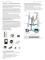
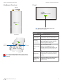
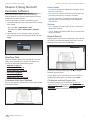
Network Topology Requirements
• A DHCP-enabled network (for the wired Access Point to
obtain an IP address as well as for the wireless Access
Points after the deployment)
• A management station computer running the UniFi
Controller software, located either onsite and connected
to the same Layer-2 network, or off-site in a cloud or
NOC
or
On-Site
Management Station
UAP-Outdoor
UAP-Outdoor
Wireless
Uplinked
1
UAP-Outdoor
UAP-Outdoor 5G
UAP-Outdoor 5G
Router
Off-Site
Cloud/NOC
2
Sample Network Topology
¹ Please refer to “Wireless Uplinks” on page 36 for
setting up wireless-linked APs.
² All UniFi APs support off-site management controllers.

2
Chapter 1: Product OverviewUniFi
™
AP-Outdoor User Guide
Ubiquiti Networks, Inc.
Hardware Overview
Connect to
Antennas
Removable Cover
Secondary
Ethernet Port
Main
Ethernet Port
Note: The Secondary Ethernet Port can be used as
as an uplink for other devices once they have been
adopted.
Front
LED Indicates the status of the device. See
the table below for details.
LED Color Status
Flashing Amber Initializing after startup.
Steady Amber Factory default, waiting to be integrated.
Alternating
Amber/Green
Device is busy; do not touch or unplug it.
This usually indicates a process such as a
firmware upgrade is taking place.
Quickly Flashing
Green
This is used to locate an AP.
When you click Locate in the UniFi
Controller software, the AP will flash. It will
also display the location of the AP on the
map.
Steady Green
Indicates the device has been successfully
integrated into a network and is working
properly.
Steady Green
with occasional
flashing
Indicates the device is in an isolated state
(all WLANs are brought down until an
uplink is found).

3
Chapter 2: InstallationUniFi
™
AP-Outdoor User Guide
Ubiquiti Networks, Inc.
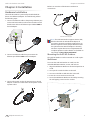
Chapter 2: Installation
Hardware Installation
The UniFi AP-Outdoor is powered by the included PoE
(Power over Ethernet) Adapter. To install the AP, perform
the following steps:
1. Connect an Ethernet cable to the primary Ethernet port
on the UniFi AP-Outdoor, and connect the other end of
the Ethernet cable to the Ethernet port labeled POE on
the PoE Adapter.
2. Connect an Ethernet cable from your LAN to the
Ethernet port labeled LAN on the PoE Adapter.
3. Connect the power cord to the power port on the PoE
Adapter. Connect the other end to of the power cord to
a power outlet.
Below is an overview of the Power over Ethernet
connections.
Power Connection Diagram
Note: The UniFi AP-Outdoor supports Passive PoE,
which works with the included PoE adapter. If
you want to power the UniFi AP-Outdoor from an
802.3af compliant switch, Ubiquiti Networks offers
the optional Instant 802.3af Adapter to instantly
transform any PoE device into a fully 48V, 802.3af
compliant product. Product details are available on
our website at http://ubnt.com/8023af
Mounting the UniFi AP-Outdoor
The UniFi AP-Outdoor can be mounted on a wall or pole.
Wall Mount
To mount the UniFi AP-Outdoor on a wall, use the
included Wall Mount Bracket, screws, and anchors.
1. Align the Wall Mount Bracket to the desired position on
a wall.
2. Use a pencil to mark the holes on the wall.
3. Use a 6 mm drill bit to drill the holes in the wall.
4. Insert the 3 screw anchors into the wall.
5. Secure the Wall Mount Bracket to the wall by inserting
the self tapping screws into the anchors.

4
Chapter 2: InstallationUniFi
™
AP-Outdoor User Guide
Ubiquiti Networks, Inc.
6. Align the notches on the UniFi AP-Outdoor with the
notches on the Wall Mount Bracket, and slide the UniFi
AP-Outdoor down until it locks into place.
Pole Mount
To mount the UniFi AP-Outdoor on a pole, use the
included Metal Strap.
1. Open the Metal Strap by turning the locking
mechanism counter-clockwise. You can loosen it by
hand or use a flathead screwdriver.
2. Straighten out the end of the Metal Strap and slide it
through the back of the UniFi AP-Outdoor.
3. Wrap the Metal Strap around the pole and use a
flathead screwdriver to tighten the locking mechanism
by turning it clockwise.
Antenna Installation
Connect each antenna to an antenna connector by
rotating it clockwise.

5
Chapter 2: InstallationUniFi
™
AP-Outdoor User Guide
Ubiquiti Networks, Inc.
Software Installation
Insert the UniFi Controller software CD into your CD-ROM
drive and follow the instructions for your specific
computer type.
Mac Users
1. Click the Install icon.
2. Click Continue and follow the on-screen instructions to
install the software.
3. Go to Go > Applications and double-click the UniFi
icon.
Proceed to”Configuring the UniFi Controller Software”
on page 6.
PC Users
1. Launch UniFi-installer.exe.
2. Click Install.
3. If your computer doesn’t have Java 1.6 or above
installed, you will be prompted to install it. Click Install
to continue.
4. Click Next.
5. Ensure that the Start UniFi Controller after installation
option is checked and click Finish.
Note: The UniFi Controller software can also be
launched from Start > All Programs.

6
Chapter 2: InstallationUniFi
™
AP-Outdoor User Guide
Ubiquiti Networks, Inc.
Configuring the UniFi Controller Software
1. The UniFi Controller software startup will begin. Click
Launch a Browser to Manage Wireless Network.
2. Select your language and country. Alternatively, you
click restore from a previous backup to use a file that
contains your backup settings. Click Next.
Note: U.S. product versions are locked to the U.S.
Country Code to ensure compliance with FCC
regulations.
3. Select the devices that you want to configure and click
Next.
4. The UniFi Installation Wizard will create a secure
primary wireless network for your devices. Perform the
following steps:
a. Enter the wireless network name (SSID) in the Secure
SSID field.
b. Enter a passphrase to be used for your primary
network in the Security Key field.
c. To enable guest access, select Enable Guest Access
and enter a guest network name in the Guest SSID
field.
d. Click Next.
5. Enter an admin name in the Admin Name field and
password in the Password field to use when accessing
the management interface. Confirm your password in
the Confirm field. Click Next.
6. Review your settings. Click Back to make changes or
Finish to save your settings. Once finished you will be
redirected to the management interface via your Web
browser.
Congratulations, your wireless network is now configured.
A login screen will appear for the UniFi Controller
management interface. Enter the admin name and
password that you created and click Login.
Proceed to the next chapter for information on using the
UniFi Controller software.

7
Chapter 3: Using the UniFi Controller SoftwareUniFi
™
AP-Outdoor User Guide
Ubiquiti Networks, Inc.
Chapter 3: Using the UniFi
Controller Software
The UniFi Controller software that comes with your
UniFi AP-Outdoor has a browser-based interface for easy
configuration and management.
To access the interface, perform the following steps:
1. Launch the UniFi Controller application if hasn’t already
been started.
•Mac users: Go > Applications > UniFi
•Windows users: Start > All Programs > Ubiquiti
UniFi.
2. The UniFi login screen will appear. Enter the admin
name and password in the appropriate fields and click
Login.
Interface Tabs
The UniFi software consists of six primary tabs. This User
Guide covers each tab with a chapter. For details, on a
specific tab, refer to the appropriate chapter.
• “Map Tab” on page 14
• “Statistics Tab” on page 21
• “Access Points Tab” on page 23
• “Users Tab” on page 25
• “Guests Tab” on page 27
• “Offline Clients Tab” on page 29
Common Interface Options
The common interface options are accessible from all tabs
in the UniFi interface.
Access Points
• connected Drop-down clickable list of all of the Access
Points that are online.
• disconnected Displays a list of Access Points that were
previously online but are no longer accessible.
• pending Drop-down clickable list of all of the Access
Points that are not yet managed but are available for
management.
Stations
• users Displays the total number of users connected to
the primary network.
• guests Displays the total number of users connected to
the guest network.
Recent Events
Displays a list of recent events including the date and time
the event occurred and the details of the event. The User
and Access Point names are clickable links.
Event Slider Move the slider right and left to navigate
between pages of events.
Search Allows you to enter text you want to search for.
Simply begin typing; there is no need to press Enter.
Clicking on an Event Device Link
The event messages have clickable links [in brackets
underlined in gray text] for AP (see “Access Point Details”
on page 30), User, and Guest (see “User/Guest Details”
on page 40). Details vary based on the selection.

8
Chapter 3: Using the UniFi Controller SoftwareUniFi
™
AP-Outdoor User Guide
Ubiquiti Networks, Inc.
Alerts
Important events are displayed in the alerts window. The
date and time of the event and the message are displayed.
Search Allows you to enter text you want to search for.
Simply begin typing; there is no need to press Enter.
Show Archived Show all of the alert messages that have
been archived.
Archive All Archive all of the alert messages displayed on
the screen.
Adopt Click to adopt an Access Point that is waiting for
adoption.
Archive Archive the selected alert message.
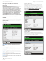
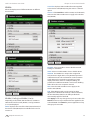
Settings
System System related settings.
Guest Control Guest portal and policies.
Wireless Networks Wireless networks.
Blocked Devices List of blocked wireless
devices.
>_
Admin Settings Admin username, password,
and preferences.
User Groups User Group settings.
Settings > System
System Configuration
System Name Editable field with the system name.
Country Select your country from the drop-down list.
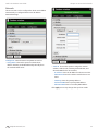
Services
Automatic Upgrade When enabled, this option will
automatically upgrade your firmware when an update is
available.
LED When enabled, the LED on the Access Point will light
up. When disabled, the LED will turn off.
Background Scanning When this option is enabled, all
managed Access Points will scan in the background for
“Rogue Access Points” – third-party or UniFi Access Points
that are being managed by another instance of the UniFi
Controller software. This option is disabled by default.
• Scan Now When clicked, all managed Access Points
will scan across all maps for two to three seconds. New
Access Points in their default state will appear under
Access Points > Pending.
Load Balancing Sets a desired number of clients per AP.
While an AP will allow more clients to connect, it will start
to look at those with lower signals and disconnect them.
Network Discovery When enabled, this option allows
UniFi to be discoverable via UPnP. This option is disabled
by default.
Uplink Connectivity Monitor It monitors the uplinks of
the managed Access Points, either wired or wireless, by
checking to see if the gateway/custom IP can be reached.
The monitor and wireless uplink capability are enabled by
default.
• Use default gateway Use default gateway is selected by
default; all managed Access Points will use the gateway
of the Access Point that is providing IP information,
either by DHCP or Static designation.
• Use custom IP Select Use custom IP to specify an
IP address; all managed Access Points will use the IP
address you enter in the Uplink IP address field.

9
Chapter 3: Using the UniFi Controller SoftwareUniFi
™
AP-Outdoor User Guide
Ubiquiti Networks, Inc.
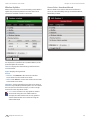
Remote Logging Enable to define a remote syslog server.
Enter the IP address and port of the syslog server.
Click Apply to save any changes that you have made.
Mail Server
When enabled, UniFi will send email alerts when triggered
(Pending Access Points and Disconnected Access Points)
to the administrator email address specified under
Settings>Admin Settings > Admin Preferences > Email Alert.
SMTP Server Enable by selecting the checkbox
and entering the outgoing (SMTP) mail server name.
Optionally, you may enable Secure Sockets Layer (SSL) to
provide communication security over the Internet. The
port number will automatically change to 465.
Enable authentication Enable by selecting the checkbox
and entering the username and password required by the
mail server.
Test SMTP Server Enter an email address and click Send
to test the mail server setup.
Apply Click Apply to save changes.
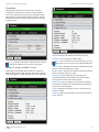
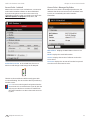
Settings > Guest Control
Guest Policies
Guest Portal This option is disabled by default. When
disabled, guests can access the Internet without entering
a password or accepting Terms of Use. When this option is
enabled, you can control the Guest Portal.
Authentication When the Guest Portal is enabled, the
authentication options will appear. There are four different
authentication methods available:
• No authentication When this option is selected, guests
are not required to log in, but must accept the Terms
of Use. When you select No authentication, you must
select Guest Policy under Settings > Wireless Networks >
SSID > Edit > Wireless Configurations in order to enforce
selection of the Terms of Use by the guest.
• Simple Password When this option is selected, guests
are required to enter the simple password and accept
the Terms of Use. When you select Simple Password,
you must select Guest Policy under Settings > Wireless
Networks > SSID > Edit > Wireless Configurations in order
to enforce entry of the password and selection of the
Terms of Use by the guest.
• Hotspot When selected, enables Hotspot functionality
including the ability to customize portal login pages and
bill customers using major credit cards or via PayPal™.
When you select Hotspot, you must select:
• Voucher or Payment in the Hotspotsectionasa
method of Hotspot authorization
• Guest Policy to enforce entry of voucher, payment,
and Terms of Use by the guest (Go to Settings >
Wireless Networks > Name_of_wireless_network > Edit >
Wireless Configurations.)
• External Portal Server If using an external server
to host a custom guest portal, enter the IP address in
the Custom Portal > IP Address box using the following
format: 192.168.0.0.
• Guest Password (Option only available when using
Simple Password authentication) Enter a password that
guests must enter before accepting the Terms of Use
and connecting to the Internet.

10
Chapter 3: Using the UniFi Controller SoftwareUniFi
™
AP-Outdoor User Guide
Ubiquiti Networks, Inc.
• Expiration (Option only available when using No
authentication or Simple Password authentication)
Allows the specification of guest login expiration after
a designated period of time. Options include: 8 hours,
24 hours, 2 days, 3 days, 4 days, 7 days, and User-defined.
User-defined can be designated in minutes, hours, and
days.
• Custom Portal (Option only available when using
External Portal Server authentication) Enter the IP
address using the following format: 192.168.0.0.
• Landing Page (Option only available when using
No authentication, Simple Password, or Hotspot
authentication) The landing page is the page where
guests are redirected after accepting the Terms of Use.
There are two options available:
- Redirect to the original URL When this option
is selected, guests are directed to the URL they
requested after accepting the Terms of Use.
- Promotional URL When this option is selected,
guests are redirected to the URL that you specify here
after accepting the Terms of Use. Specify the URL with
http:// in front of the Web address.
Example: http://www.ubnt.com
• Portal Customization (Option only available when
using No authentication, Simple Password, or Hotspot
authentication) When enabled, allows customized portal
pages to appear in place of default login pages. See
“Portal Customization” on page 44 for details on
setting up custom portal pages.
• Portal URL Hostname Allows the designation of a
hostname for the portal URL in place of the default
IP address. Paired with a SSL certificate, ensures site
certificates are displayed as trusted in the guest browser.
Example: www.ubnt.com
Hotspot
The Hotspot options are only available when Hotspot
authentication is selected.
• Voucher When selected, vouchers (including
distributable code, duration values, and use restrictions)
can be created using Hotspot Manager (see “Hotspot
Manager” on page 42).
• Payment When enabled, allows payment-based
authentication to be set up with your PayPal Website
Payments Pro account. Payments and Transactions can
be managed using Hotspot Manager (see “Hotspot
Manager” on page 42).
• PayPal PayPal account details are entered here:
- Username Enter the corresponding Username.
- Password Enter the corresponding Password.
- Signature Enter the corresponding Signature for the
PayPal account to be used for receiving payments.
- Use Paypal Sandbox For PayPal testing purposes,
enable this option and click Apply Sandbox
Account to set up/access your PayPal Sandbox Test
Environment.
• Hotspot Operator Click Go to Hotspot Manager
to manage Wireless Guests, Payments/Transactions,
Vouchers, and Operator Accounts. See “Hotspot
Manager” on page 42.
• Apply Click Apply to save changes.
When logging in with No authentication, guests will be
required to accept the Terms of Use before gaining access
to the Internet.
When logging in with Simple Password authentication,
guests will be required to enter the Guest Password and
accept the Terms of Use before gaining access to the
Internet.
When logging in with Voucher-based Hotspot
authentication, guests will be required to enter the
voucher number and accept the Terms of Use before
gaining access to the Internet.

11
Chapter 3: Using the UniFi Controller SoftwareUniFi
™
AP-Outdoor User Guide
Ubiquiti Networks, Inc.
When logging in with Payment-based Hotspot
authentication, guests will be required to select the
package type, click the payment choice, and accept the
Terms of Use before gaining access to the Internet.
Access Control
Restricted Subnets Enter any subnets that you don’t
want guests to be able to access.
Apply Click Apply to save changes.
Settings > Admin Settings
Admin Name Displays the current admin name used to
log in. To change the admin name, simply enter a new
name and click Apply.
Password A new password can be entered in this field.
Ensure that you enter the password again in the Confirm
field and then click Apply to save your new password.
Confirm Used to confirm your new password.
Language Selects the language for use in the interface.
Email Alert Select to enable email alerts and enter the
administrator email address in the Send alert to email
box. See “Mail Server” on page 9 for information on
setting up the outgoing (SMTP) mail server.
Apply Click Apply to save changes.
Settings > Wireless Networks
Wireless Configurations
Name Displays the wireless network name (SSID).
Security Displays the type of security being used on your
wireless network.
Guest Network Indicates whether the network is a guest
network.
Actions Select an action button to perform the desired
action:
• Edit Select to make changes to the wireless network
settings.
• Delete Select to delete the wireless network.
Wireless Configuration
• Name/SSID Allows you to edit the wireless network
name (SSID).
• Security Selects the type of security to use on your
wireless network.
- Open This option is typically only used on the Guest
network. When enabled, wireless network access is
open to anyone without needing a password.
- WEP WEP (Wired Equivalent Privacy) is the oldest and
least secure security algorithm. WPA security methods
should be used when possible.
• WEP Key Enter a WEP encryption key in
hexadecimal format. You can enter a 64-bit or
128-bit key:
Type Hex
64-bit 10 Hexadecimal Characters
(0-9, A-F, or a-f)
Example: 00112233AA
Note: You can use 5 printable characters,
which will be translated to the
corresponding HEX code.
128-bit 26 Hexadecimal Characters
(0-9, A-F, or a-f)
Example:
00112233445566778899AABBCC
Note: You can use 13 printable
characters, which will be translated to the
corresponding HEX code.
• Key Index Specifies the Index of the WEP Key used.
Four different WEP keys can be configured at the
same time, but only one is used. The effective key is
set by choosing 1, 2, 3 or 4.

12
Chapter 3: Using the UniFi Controller SoftwareUniFi
™
AP-Outdoor User Guide
Ubiquiti Networks, Inc.
- WPA-Personal WPA™ or Wi-Fi Protected Access was
developed as an encryption method stronger than
WEP. WPA-Personal requires a passphrase to connect
to the wireless network.
• Security Key Enter the passphrase that users will
use to connect to the wireless network.
- WPA-Enterprise WPA Enterprise uses a RADIUS
server to authenticate users on the wireless network.
• IP Address This is where the IP address of the
RADIUS server is specified.
• Port The port number is entered here. By default it
is 1812.
• Password The password used to authenticate on
the RADIUS server is entered here.
• Guest Policy Select this option to enable guest access
policies on this wireless network.
Advanced
• VLAN To use a VLAN, select Use VLAN ID and enter the
port number.
• Hide SSID Select this option if you don’t want the SSID
to be broadcast.
• WPA Defines supported WPA and encryption methods.
• User Group Allows assignment of wireless users to a
specific user group.
Click Apply to save any changes that you have made.
Click Cancel to discard changes.
Settings > Blocked Devices
Displays the list of blocked wireless devices.
Unblock Click to unblock a wireless device. See “User/
Guest Details” on page 40 for information on blocking
wireless devices.
Settings > User Groups
Create Click to create a new user group.
• Name Enter a descriptive user group name.
• Bandwidth Limit (Download) When selected, allows
the designation of a download bandwidth limit in Kbps.
• Bandwidth Limit (Upload) When selected, allows the
designation of an upload bandwidth limit in Kbps.
- Create Click to create a user group.
- Cancel Click to cancel user group creation.
Edit Click to change the name or bandwidth settings of
the user group.
Delete Click to delete the user group.
See “Configuration” on page 41 for information on the
application of User Groups to Users/Guests.

13
Chapter 3: Using the UniFi Controller SoftwareUniFi
™
AP-Outdoor User Guide
Ubiquiti Networks, Inc.
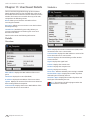
Admin
The Admin tab displays server version information,
allows system backups to be created and downloaded,
allows system restoration from backup files, and allows
configuration information to be downloaded to assist in
support issues.
Server Information
Version The software version is displayed here. If there
is an update, UniFi will automatically download it and
display it here.
Backup
Download Backup Settings Click to download a file that
contains all of your settings so you can restore them later
if you choose.
Restore
Choose File Select this option to restore settings from a
backup file that you’ve already downloaded.
Support Info
Download Support Info Select this option to download
a file to your computer with information about your
configuration that can be emailed to our support team.

14
Chapter 4: Map TabUniFi
™
AP-Outdoor User Guide
Ubiquiti Networks, Inc.
Chapter 4: Map Tab
The UniFi Controller software allows you to upload custom
map images of your location(s) or use Google Maps
™
for a
visual representation of your wireless network. When you
initially launch the UniFi Controller application, a default
map is displayed.
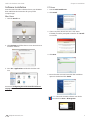
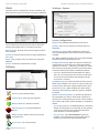
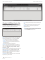
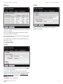
Adding Custom Maps
To add a custom map, you must first create the image
using an illustration, image editing, or blueprint
application that exports .jpg, .gif, or .png file formats.
Once you’ve created the map, you can upload it to the
UniFi Controller software by performing the following
steps:
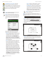
1. Click Configure Maps.
Configure Maps button

15
Chapter 4: Map TabUniFi
™
AP-Outdoor User Guide
Ubiquiti Networks, Inc.
2. Click Add a Map.
Add a Map
3. Enter a map name in the Description field and click
Upload my own. Click the Browse button to locate the
file to use as a map (valid file formats are .jpg, .gif, and
.png). Click Continue.
4. Click Close.
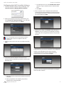
Adding a Google Map
To add a Google Map to the UniFi Controller software Map
view:
1. Click Configure Maps.
Configure Maps button
2. Click Add a Map.
Add a Map

16
Chapter 4: Map TabUniFi
™
AP-Outdoor User Guide
Ubiquiti Networks, Inc.
3. Enter a map name in the Description field and click Use
Google Maps. Click Continue.
4. In order to use a Google Map, you must register with
Google for a Google Maps API key. To do so, click
Specify API Key.
5. Click or copy and paste the Web link from the window
into a new Web browser window. Do not close the
UniFi window.
http://code.google.com/apis/maps/signup.html
6. You need to be signed in with a Google account to
obtain a Google Maps API key.
7. Review the terms and conditions and click the
checkbox next to I have read and agree with the
terms and conditions.
8. Navigate back to the UniFi window and copy the
address that UniFi displays in the address bar.
Note: You only need to copy until the end of the
address; do not include the port information.
In the example below, the full address is
https://192.168.25.191:8443/manage#. You only
need to copy up to https://192.168.25.191. Do not
include the colon or anything beyond it.
9. Navigate back to the Google Maps API Family window
and paste the address into the My web site URL: box.
10. Click the Generate API Key button.
11. A new window will open, displaying your key. Highlight
and copy the Google Maps API key.
Google Maps API Key
12. Navigate back to the UniFi window and paste the API
Key into the API Key field. Click continue.

17
Chapter 4: Map TabUniFi
™
AP-Outdoor User Guide
Ubiquiti Networks, Inc.
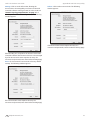
13. The default Google Map location will appear. Click the
Set Location button in the lower left.
Set Location button
14. Select Specify Address to enter an address. Type in the
address and then click Go. You also have the Specify
Coordinates option to enter the latitude and longitude
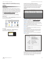
of a specific location.
15. The specified location should appear. Click Save.
16. Click Close.
17. You can adjust the zoom using the slider on the right.
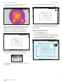
Placing Access Points on the Map
1. Drag the Access Point icon(s) from the Unplaced APs list
on the left to the appropriate location(s) on the map.
The access point will appear in the area that you placed it.
La pagina si sta caricando...
La pagina si sta caricando...
La pagina si sta caricando...
La pagina si sta caricando...
La pagina si sta caricando...
La pagina si sta caricando...
La pagina si sta caricando...
La pagina si sta caricando...
La pagina si sta caricando...
La pagina si sta caricando...
La pagina si sta caricando...
La pagina si sta caricando...
La pagina si sta caricando...
La pagina si sta caricando...
La pagina si sta caricando...
La pagina si sta caricando...
La pagina si sta caricando...
La pagina si sta caricando...
La pagina si sta caricando...
La pagina si sta caricando...
La pagina si sta caricando...
La pagina si sta caricando...
La pagina si sta caricando...
La pagina si sta caricando...
La pagina si sta caricando...
La pagina si sta caricando...
La pagina si sta caricando...
La pagina si sta caricando...
La pagina si sta caricando...
La pagina si sta caricando...
La pagina si sta caricando...
La pagina si sta caricando...
La pagina si sta caricando...
La pagina si sta caricando...
La pagina si sta caricando...
La pagina si sta caricando...
La pagina si sta caricando...
La pagina si sta caricando...
-
 1
1
-
 2
2
-
 3
3
-
 4
4
-
 5
5
-
 6
6
-
 7
7
-
 8
8
-
 9
9
-
 10
10
-
 11
11
-
 12
12
-
 13
13
-
 14
14
-
 15
15
-
 16
16
-
 17
17
-
 18
18
-
 19
19
-
 20
20
-
 21
21
-
 22
22
-
 23
23
-
 24
24
-
 25
25
-
 26
26
-
 27
27
-
 28
28
-
 29
29
-
 30
30
-
 31
31
-
 32
32
-
 33
33
-
 34
34
-
 35
35
-
 36
36
-
 37
37
-
 38
38
-
 39
39
-
 40
40
-
 41
41
-
 42
42
-
 43
43
-
 44
44
-
 45
45
-
 46
46
-
 47
47
-
 48
48
-
 49
49
-
 50
50
-
 51
51
-
 52
52
-
 53
53
-
 54
54
-
 55
55
-
 56
56
-
 57
57
-
 58
58


Ubiquiti UAP-Outdoor 5G Manuale utente
- Categoria
- Punti di accesso WLAN
- Tipo
- Manuale utente
- Questo manuale è adatto anche per
in altre lingue
- English: Ubiquiti UAP-Outdoor 5G User manual
Documenti correlati
-
Ubiquiti UAP-Outdoor Manuale utente
-
Ubiquiti UAP-AC Manuale utente
-
-
-
-
-
Ubiquiti UniFi Enterprise Guida Rapida
-
Ubiquiti Networks UAP-AC-M Manuale utente
-
-
Altri documenti
-
-
-
Buffalo HD-PZN1.0U3B Guida utente
-
Johnson Controls MAP 1810 Guida Rapida
-
Senao Networks U2M-OC36600802 Manuale utente
-
CAME CCTV Guida d'installazione
-
-
 visel QS-SWLITE Manuale del proprietario
-
 Chase Ingenico IWL250 Quick Reference Manual
-
AXI Sandbox with bench Manuale utente

