Carrier 40SMC036N Guida utente
- Categoria
- Condizionatori d'aria a sistema split
- Tipo
- Guida utente

DUCTED ABOVE-CEILING UNITS (COOLING ONLY AND HEAT PUMP)
Installation, operation and maintenance instructions
UNITÀ CANALIZZABILE A SOFFITTO (SOLO RAFFRESCAMENTO E POMPA DI CALORE)
Istruzioni di installazione, uso e manutenzione
UNITÉ SPLIT GAINABLE ET ENCASTRABLE (FROID SEUL ET POMPE À CHALEUR)
Instructions d’installation, mode d’emploi et d’entretien
KANALISIERTES DECKENGERÄT(KÜHLGERÄTE UND WÄRMEPUMPEN)
Installations, Bedienungs- und Wartungsanweisungen
CLIMATIZADORAS BAJA SILUETA (FRÍO SOLO Y BOMBA DE CALOR)
Instrucciones de instalación, funcionamiento y mantenimiento
•
L
L
O
Y
D
'
S
R
E
G
I
S
T
E
R
Q
U
A
L
I
T
Y
A
S
S
U
R
A
N
C
E
I
S
O
9
0
0
1
40SMC---N

2
Indice
pagina
Norme di sicurezza ............................... 4/5
Dati fisici................................................ 6/7
Dati elettrici ......................................... 8/11
Limiti di funzionamento ..................... 12/13
Dimensioni ........................................ 14/15
Area di servizio ...................................... 16
Installazione ...................................... 16/21
Collegamenti elettrici......................... 22/23
Schemi elettrici.................................. 24/27
Collegamento linea refrigerante
(attacchi a cartella)............................ 28/29
Manutenzione e cura ........................ 30/31
Ricerca dei guasti ............................. 30/33
Raccomandazioni finali ..................... 32/33
Diagrammi ventilatore ....................... 34/35
Contents
page
Safety considerations............................ 4/5
Physical data......................................... 6/7
Electrical data ..................................... 8/11
Operating limits ................................. 12/13
Dimensions ....................................... 14/15
Service area ........................................... 16
Installation ......................................... 16/21
Electrical connections ....................... 22/23
Electric diagrams .............................. 24/27
Refrigerant line connection
(Flare connnections) ......................... 28/29
Maintenance and service .................. 30/31
Troubleshooting chart ....................... 30/33
Final recommendations..................... 32/33
Fan diagrams .................................... 34/35
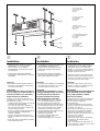
IMPORTANT:
This indoor unit is connected to
outdoor unit model
38GL(S), 38BC(S),
38BH and 38YY.
Refer to the outdoor unit installation
manual for the following paragraphs:
• Electrical connections
• Connection wire size
• System configuration
• Trial run procedure
The ceiling unit is operated by wire
controls
• Room Controller;
• Zone manager.
IMPORTANTE:
Questa unità interna viene collegata
all'unità esterna modello 38GL(S),
38BC(S), 38BH e 38YY. Consultare il
manuale di installazione dell'unità
esterna per i seguenti paragrafi:
• Collegamenti elettrici
• Sezione cavi di collegamento
• Configurazione del sistema
• Collaudo del sistema
L’unità satellite è comandabile tramite
i comandi a filo
• Room Controller;
• Zone manager.
La pagina sta caricando ...

4
Safety considerations
Norme di sicurezza
Installation and servicing of air
conditioning equipment can be hazardous
due to system pressure and electrical
components.
Only trained and qualified service
personnel should install, repair or service
air conditioning equipment.
Untrained personnel can perform the basic
maintenance functions of cleaning coils
and filters, and replacing filters.
All other operations should be performed
by trained service personnel.
When working on air conditioning
equipment, observe precautions on the
literature, tags and labels attached to the
unit and other safety precautions that may
apply.
Follow all safety codes.
Wear safety glasses and workgloves.
Use a quenching cloth for unbrazing
operations.
WARNING:
Before performing service or
maintenance operations turn off the
main power switch to unit.
Electrical discharge could cause
personal injury.
The 40SMC---N unit is designed for
installation with ducts.
If this is not the case, the installer must
place a protection mesh in the
discharge according to the standards
in force.
Only use original spare parts when
repairing and pay special attention
when positioning the same.
They must be placed indentically to the
previus ones.
These units must not be installed in an
explosive atmosphere.
The units con operate in residential,
commercial and light industrial
installations which have normal
radioelectrical atmospheres
consultation must be made for other
applications.
WARNING:
This unit base can incorporate a drain
pan. Do not drill through base or
damage to drain pan and refrigerant
circuit may result.
The air must be filtered before entering
the evaporator, or the guarantee
becomes invalid.
Do not use undue force or excessive
manipulation of the refrigerant
connections and pipes.
Ensure that no piping touches any
adjacent part.
If necessary, adjust carefullly because
the guarantee does not cover leaks due
to a negligent handling of the pipes.
Split units can contain a maintenance
charge.
Purge before de-soldering the plugs.
Le operazioni d’installazione, manutenzione
e riparazione di impianti di climatizzazione
possono risultare rischiose per la presenza
di pressione all’interno del sistema e dei
componenti elettrici. Tali operazioni
devono essere eseguite esclusivamente
da personale qualificato.
Personale non qualificato può effettuare
soltanto operazioni di manutenzione
ordinaria come ad esempio la pulizia delle
batterie e la sostituzione dei filtri.
Tutte le altre operazioni dovrebbero essere
eseguite da personale qualificato. Se si
lavora su un impianto di climatizzazione,
osservare le avvertenze riportate sulle
etichette o cartellini dell’unità e eventuali
altre norme di sicurezza.
Osservare tutte le misure di sicurezza.
Portare occhiali di protezione e guanti di
lavoro. Durante le operazioni di saldatura
utilizzare indumenti protettivi.
ATTENZIONE:
Prima di svolgere operazioni di
manutenzione e riparazione scollegare
l’unità dall’impianto elettrico centrale.
Eventuali scariche elettriche potrebbero
risultare estremamente pericolose.
L’unità 40SMC---N è progettata per
installazione canalizzata.
In caso contrario, l’installatore deve
mettere una rete di protezione sulla
mandata, in accordo alle normative in
vigore.
Durante le riparazioni usare soltanto le
“parti originali di ricambio”.
Si deve prestare particolare attenzione
alla posizione. Le parti devono essere
installate nella loro posizione originale
Questa unità non può essere installata
in un’atmosfera.
L’unità può funzionare in atmosfere
radioelettriche normali, perinstallazioni
residenziali, commerciali ed industriali.
Per altri tipi di applicazione consultare
un tecnico.
ATTENZIONE:
La base dell'unità può incorporare la
bacinella di drenaggio.
Non forare la base per evitare
danneggiamenti alla bacinella ed al
circuito frigorifero.
L'aria deve essere filtrata prima di
raggiungere l'evaporatore, pena il
decadimento della garanzia. Non piegare
troppo e non manipolare eccessivamente
i collegamenti frigoriferi e le tubazioni.
Assicurarsi che le tubazioni non siano a
contatto con altri pezzi vicini.
Se necessario sistemare con cura
poiché la garanzia non copre le perdite
dovute a un maneggiamento incorretto
delle tubazioni. Le unità split possono
contenere una carica di tenuta. Spurgare
prima di dissaldare i tappi.
La pagina sta caricando ...

6
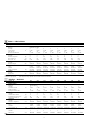
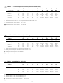
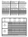
Tabella 1 - Dati fisici
40SMC---N 009 012 018 024 028 036 048 060
Peso 22 22 22 36 36 36 60 60
Batteria interna
Materiale Alluminio/Rame
Quantità 11111111
Superficie frontale m
2
0,145 0,145 0,145 0,245 0,245 0,245 0,400 0,400
Alette per pollice 14 14 14 14 12 14 12 14
Nº ranghi -diametro tubi 2...3/8” 2...3/8” 3...3/8” 2...3/8” 3...3/8” 3...3/8” 3...3/8” 3...3/8”
Motore del ventilatore
Quantità 11111111
Condensatore elettrico µF 4 5 4,5 5,5 6,3 8 6 8
Assorbimento nominale (1) W 80 90 100 190 220 305 420 560
Corrente nominale (1) Amp 0,36 0,40 0,45 0,85 1,0 1,35 1,90 2,50
Ventilatore
Quantità 22222222
Diametro - lunghezza mm 146x176 146x176 146x176 185x240 185x240 185x240 200x240 200x240
Refrigerante
Tipo
R-410A R-410A R-410A R-410A R-410A R-410A R-410A
R-410A
Controllo Orifizio Orifizio Orifizio Orifizio Orifizio Orifizio Orifizio Orifizio
Carica approx. (2) Kg Vedere nota Vedere nota Vedere nota Vedere nota Vedere nota Vedere nota Vedere nota Vedere nota
Filtro dell'aria Lavabile Lavabile Lavabile Lavabile Lavabile Lavabile Lavabile Lavabile
Quantità 11111111
DImensioni mm 685x218 685x218 685x218 684x283 684x283 684x283 1172x308 1172x308
Table 1 - Phisical data
40SMC---N 009 012 018 024 028 036 048 060
Weight 22 22 22 36 36 36 60 60
Indoor coil
Material Aluminium / Copper
Quantity 11111111
Front surface m
2
0.145 0.145 0.145 0.245 0.245 0.245 0.400 0.400
Fins per inch 14 14 14 14 12 14 12 14
Nº rows-tube diameter 2...3/8” 2...3/8” 3...3/8” 2...3/8” 3...3/8” 3...3/8” 3...3/8” 3...3/8”
Fan motor
Quantity 11111111
Electrical capacitor µF 4 5 4.5 5.5 6.3 8 6 8
Nom. power (1) W 80 90 100 190 220 305 420 560
Nom. cons. (1) Amp 0.36 0.40 0.45 0.85 1.0 1.35 1.90 2.50
Fan
Quantity 22222222
Diameter-lenght mm 146x176 146x176 146x176 185x240 185x240 185x240 200x240 200x240
Refrigerant
Type
R-410A R-410A R-410A R-410A R-410A R-410A R-410A
R-410A
Control Restrictor Restrictor Restrictor Restrictor Restrictor Restrictor Restrictor Restrictor
Approx. charge (2) Kg See note See note See note See note See note See note See note See note
Air filter Washable Washable Washable Washable Washable Washable Washable Washable
Quantity 11111111
DImensions mm 685x218 685x218 685x218 684x283 684x283 684x283 1172x308 1172x308
NOTES:
(1) Motor on high speed. (2) Refrigerant charge depends on the outdoor unit to be connected.
NOTE:
(1) Motore alla alta velocità (2) La carica di refrigerante dipende dall’unità esterna a cui l’unità stessa deve essere collegata
La pagina sta caricando ...

8
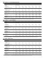
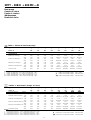
Table 2 - Electrical data (cooling only)
38GL(S) - 38BC(S) 09 12 18 24 28 36 48 60
+ ++ ++++++
40SMC---N 009 012 018 024 028 036 048 060
Operation voltage V/Ph/Hz ❍❍❍❍❍/●❍/●●●/●●●/●
CONSUMPTION
Nominal * kW 1.03 1.23 1.82 2.26 2.80 3.53 4.05 5.20
Amp 4.56 5.45 8.23 10.20 12.67/4.22 16.0/5.32 13.6/7.80 18.6/10.7
Máximum ** kW 1.23 1.47 2.18 2.71 3.36 4.23 4.50 6.60
Amp 5.56 6.65 9.86 12.30 15.20/5.06 19.15/6.37 15.07/8.67 23.6/13.6
On short circuit Amp 28.5 35.0 51.5 78.0 84.5/47.5 108.0/49.0 103.0/53.0 124.0/64.0
NOTES:
* Outdoor dry bulb temperature = 35
o
C; Indoor wet bulb temperature = 19
o
C.
** Outdoor dry bulb temperature = 46
o
C; Indoor wet bulb temperature = 21
o
C.
❍ Outdoor unit operation voltage 230V ~ 50Hz
● Outdoor unit operation voltage 400V 3N~ 50Hz
●● Outdoor unit operation voltage 230V 3N~ 50Hz
Tabella 2 - Dati elettrici (solo raffrescamento)
38GL(S) - 38BC(S) 09 12 18 24 28 36 48 60
+ ++ ++++++
40SMC---N 009 012 018 024 028 036 048 060
Tensione nominale V/Ph/Hz
❍❍❍❍❍
/
●❍
/
●●●
/
●●●
/
●
ASSORBIMENTO
Nominale * kW 1,03 1,23 1,82 2,26 2,80 3,53 4,05 5,20
Amp 4,56 5,45 8,23 10,20 12,67/4,22 16,0/5,32 13,6/7,80 18,6/10,7
Massimo** kW 1,23 1,47 2,18 2,71 3,36 4,23 4,50 6,60
Amp 5,56 6,65 9,86 12,30 15,20/5,06 19,15/6,37 15,07/8,67 23,6/13,6
Corrente di spunto Amp 28,5 35,0 51,5 78,0 84,5/47,5 108,0/49,0 103,0/53,0 124,0/64,0
* Temperatura esterna b.s. = 35
o
C; Temperatura interna b.u. = 19
o
C.
** Temperatura esterna b.s. = 46
o
C; Temperatura interna b.u. = 21
o
C.
❍
Unità esterna con tensione nominale 230V ~ 50Hz
●
Unità esterna con tensione nominale 400V 3N~ 50Hz
●●
Unità esterna con tensione nominale 230V 3N~ 50Hz
NOTE:
38GL(S) - 38BC(S) + 40SMC---N
Cooling only
Solo raffrescamento
Refroidissement seul
Nur Kühlung
Sólo frío
La pagina sta caricando ...

10
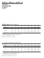
Table 4 - Electrical data (heat pump)
38YY - 38BH 09 12 18 24 28 36 48 60
+ ++ ++++++
40SMC---N 009 012 018 024 028 036 048 060
Operation voltage V/Ph/Hz ❍❍❍❍❍/●❍/●●●/●●●/●
CONSUMPTION
Nominal (on cooling) * kW 1,00 1.22 1.79 2.20 2.77 3.48 4.0 5.15
Amp 4,52 5.52 8.10 10.10 12.53/4.77 15.75/5.24 13.5/7.95 18.4/10.6
Nominal (on heating) ** kW 0,92 1.10 1.67 2.20 2.61 2.74 3.80 4.65
Amp 4,16 4.97 7.56 10.10 11.80/3.93 12.40/4.13 13.7/7.9 17.2/9.90
Máximum (on coolig) *** kW 1,20 1.46 2.15 2.69 3.32 4.17 4.43 6.58
Amp 5,43 6.60 9.73 12.17 15.02/5.0 18.87/6.28 14.8/8.53 23.6/13.58
Máximum (on heating) **** kW 1,10 1.32 2.00 2.04 3.13 3.29 5.11 6.0
Amp 4,98 5.97 9.05 9.23 14.16/4.71 14.89/4.95 17.1/9.84 21.5/12.38
On short circuit Amp 28,5 35.0 51.5 78.0 84.5/47.5 108.0/49.0 103.0/53.0 124.0/64.0
NOTES:
* Outdoor dry bulb temp. = 35
o
C; Indoor wet bulb temp. = 19
o
C.
** Outdoor wet bulb temp. = 6
o
C; Indoor dry bulb temp. = 21
o
C.
*** Outdoor dry bulb temp. = 46
o
C; Indoor wet bulb temp. = 21
o
C.
**** Outdoor wet bulb temp. = 18
o
C; Indoor dry bulb temp. = 24
o
C.
Tabella 4 - Dati elettrici (Pompa di calore)
38YY - 38BH 09 12 18 24 28 36 48 60
+ ++ ++++++
40SMC---N 009 012 018 024 028 036 048 060
Tensione nominale V/Ph/Hz
❍❍❍❍❍
/
●❍
/
●●●
/
●●●
/
●
ASSORBIMENTO
Nominale (raffrescamento) * kW 1,00 1,22 1,79 2,20 2,77 3,48 4,0 5,15
Amp 4,52 5,52 8,10 10,10 12,53/4,77 15,75/5,24 13,5/7,95 18,4/10,6
Nominale (riscaldamento) ** kW 0,92 1,10 1,67 2,20 2,61 2,74 3,80 4,65
Amp 4,16 4,97 7,56 10,10 11,80/3,93 12,40/4,13 13,7/7,9 17,2/9,90
Massimo (raffrescamento) *** kW 1,20 1,46 2,15 2,69 3,32 4,17 4,43 6,58
Amp 5,43 6,60 9,73 12,17 15,02/5,0 18,87/6,28 14,8/8,53 23,6/13,58
Massimo (riscaldamento) **** kW 1,10 1,32 2,00 2,04 3,13 3,29 5,11 6,0
Amp 4,98 5,97 9,05 9,23 14,16/4,71 14,89/4,95 17,1/9,84 21,5/12,38
Corrente di spunto Amp 28,5 35,0 51,5 78,0 84,5/47,5 108,0/49,0 103,0/53,0 124,0/64,0
NOTAS:
* Temperatura esterna b.s. = 35
o
C; Temperatura interna b.u = 19
o
C.
** Temperatura esterna b.u. = 6
o
C; Temperatura interna b.s. = 21
o
C.
*** Temperatura esterna b.s. = 46
o
C; Temperatura interna b.u. = 21
o
C.
**** Temperatura esterna b.u. = 18
o
C; Temperatura interna b.s. = 24
o
C.
38YY - 38BH + 40SMC---N
Heat pump
Pompa di calore
Pompe à chaleur
Wärmepumpe
Bomba de calor
❍ Outdoor unit operation voltage 230V ~ 50Hz
● Outdoor unit operation voltage 400V 3N~ 50Hz
●● Outdoor unit operation voltage 230V 3N~ 50Hz
❍
Unità esterna con tensione nominale 230V ~ 50Hz
●
Unità esterna con tensione nominale 400V 3N~ 50Hz
●●
Unità esterna con tensione nominale 230V 3N~ 50Hz
La pagina sta caricando ...

12
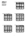
Table
6
: Operating limits
AIR TEMPERATURE
ZONE DRY BULB WET BULB
COOLING OPERATION
Indoor:
Maximum +35°C +21°C
Minimum +19°C +14°C
Outdoor:
Maximum +46°C –
Minimum +19°C * –
* With optional head pressure control, the unit
can operate at temperatures below +19°C.
Tabella
6
: Limiti di funzionamento
TEMPERATURA DELL’ARIA
ZONA SECCO UMIDO
SOLO FREDDO
Interno:
Massimo +35°C +21°C
Minimo +19°C +14°C
Esterno:
Massimo +46°C –
Minimo +19°C * –
* Con il dispositivo accessorio di regolazione
della pressione di condensazione, l’unità può
funzionare con temperature inferiori a +19°C.
Tabelle
6
: Betriebs-Grenzwerte
LUFTTEMPERATURE
ZONE
Trockenkugeltemp. Feuchtkugeltemp.
KÜHLBETRIEB
Drinnen:
Maximum +35°C +21°C
Minimum +19°C +14°C
Draußen:
Maximum +46°C –
Minimum +19°C * –
* Mit der wahlweisen Verflüssigungsdruck-Regelung
kann das Gerät bei Temperaturen unter 19°C
betrieben werden.
Tab 6: Les limites de fonctionnement
TEMPÉRATURE DE L’AIR
ZONE BULBE SEC BULBE HUMIDE
MODE REFROIDISSEMENT
Intérieure:
Maximum +35°C +21°C
Minimum +19°C +14°C
Extérieure:
Maximum +46°C –
Minimum +19°C * –
* Avec une régulation de la pression de
condensation en option, l’unité peut fonctionner
à des températures en dessous de 19°C.
40SMC---N
Cooling only
Solo raffrescamento
Refroidissement seul
Kühlbetrieb
Sólo frío
Tabla 6: Limites de operación
TEMPERATURA DEL AIRE
ZONA SECA HUMEDA
FUNCIONAMIENTO EN FRIO
Interior:
Máxima +35°C +21°C
Mínima +19°C +14°C
Exterior:
Máxima +46°C –
Mínima +19°C * –
* Con el opcional de regulación de la presión de
condensación la unidad puede funcionar con
temperaturas inferiores a + 19°C.

13
Table 7: Operating limits
AIR TEMPERATURE
ZONE DRY BULB WET BULB
COOLING OPERATION
Indoor:
Maximum +35°C +21°C
Minimum +19°C +14°C
Outdoor:
Maximum +46°C –
Minimum +19°C * –
HEAT PUMP OPERATION
Indoor:
Maximum +27°C –
Outdoor:
Maximum +24°C +18°C
Minimum -15°C –
* With optional head pressure control, the unit
can operate at temperatures below +19°C.
Tabella 7: Limiti di funzionamento
TEMPERATURA DELL’ARIA
ZONA SECCO UMIDO
SOLO FREDDO
Interno:
Massimo +35°C +21°C
Minimo +19°C +14°C
Esterno:
Massimo +46°C –
Minimo +19°C * –
FUNZIONAMENTO A POMPA DI CALORE
Interno:
Massimo +27°C –
Esterno:
Massimo +24°C +18°C
Minimo -15°C –
* Con il dispositivo accessorio di regolazione
della pressione di condensazione, l’unità può
funzionare con temperature inferiori a +19°C
Tabelle 7: Betriebs-Grenzwerte
LUFTTEMPERATURE
ZONE
Trockenkugeltemp.
Feuchtkugeltemp.
KÜHLBETRIEB
Drinnen:
Maximum +35°C +21°C
Minimum +19°C +14°C
Draußen:
Maximum +46°C –
Minimum +19°C * –
WÄRMEPUMPENBETRIEB
Drinnen:
Maximum +27°C –
Draußen:
Maximum +24°C +18°C
Minimum -15°C –
* Mit der wahlweisen Verflüssigungsdruck-
Regelung kann das Gerät bei Temperaturen
unter 19°C betrieben werden.
Tabla 7: Limites de operación
TEMPERATURA DEL AIRE
ZONA SECA HUMEDA
FUNCIONAMIENTO EN FRIO
Interior:
Máxima +35°C +21°C
Mínima +19°C +14°C
Exterior:
Máxima +46°C –
Mínima +19°C * –
FUNCIONAMIENTO EN CALOR POR BOMBA
Interior:
Máxima +27°C –
Exterior:
Máxima +24°C +18°C
Mínima -15°C –
* Con el opcional de regulación de la presión de
condensación la unidad puede funcionar con
temperaturas inferiores a + 19°C.
Tab. 7: Les limites de fonctionnement
TEMPÉRATURE DE L’AIR
ZONE BULBE SEC BULBE HUMIDE
MODE REFROIDISSEMENT
Intérieure:
Maximum +35°C +21°C
Minimum +19°C +14°C
Extérieure:
Maximum +46°C –
Minimum +19°C * –
MODE POMPE A CHALEUR
Intérieure:
Maximum +27°C –
Extérieure:
Maximum +24°C +18°C
Minimum -15°C –
* Avec une régulation de la pression de
condensation en option, l’unité peut fonctionner
à des températures en dessous de 19°C.
40SMC---N
Heat pump
Pompa di calore
Pompe à chaleur
Wärmepumpen
Bomba de calor
La pagina sta caricando ...

15
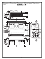
Dimensions /
Dimensioni
/ Dimensions /
Abmessungen
/ Dimensiones
(mm)
When designin an installation ensure the use of up-to-date drawings available from your local Carrier office.
Per la progettazione dell’installazione, assicurarsi di utilizzare disegni aggiornati, disponibili presso l’ufficio Carrier locale.
Pour la conception de l’installation, vérifier que l’on utilise toujours des dessins au schémas mis au jour, disponibles auprès du bureau Carrier local.
Für die Installationsplanung nur neubearbeitete Zeichnungen, die in der örtlichen Carrier Dienststelle zur Verfügung stehen, anwenden.
Para el disenõ de instalaciones utilizar los dibujos actualizados disponibles en la oficina local de Carrier.
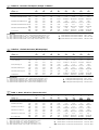
40SMC---N A B C D E F G H I J K L M N P Q R S
009 - 012 - 018 725 555 220 743 781 262 222 71 23 607 31.5 59 140 200 35 33 659 45
024 - 028 - 036 925 660 285 943 981 241.5 321 97.5 23 712 33.5 118.5 199.5 264.5 35 37.5 850 87.5
048 - 060 1250 750 310 1268 1306 261 321 168 22 801 43 143 224 289 43 110 1030 103
40SMC---N T U V W X Y Z AB AC AD AE AF AG AH AJ AK AL
009 - 012 - 018 143 62 211 179 103 13 27 3,5 89 545 33 142 31 90 128 54 38
024 - 028 - 036 165.5 90 276 193 125 23 82 31 99 725 33 207 31 110 160 50 75
048 - 060 175 203 290 264 116 23 107 31 109 1030 32 233 32 140 185 50 75
40SMC---N Ø AM Ø AN Ø AP
009 1/4” 3/8” 20
012 - 018 1/4” 1/2” 20
024 - 028 1/4” 5/8” 25
036 - 048 - 060 3/8” 3/4” 25
40SMC---N
a Indoor coil
b Fan
c Drain pan
d Drain connection Ø AP
e Outside air intake
f Electrical box
g Unit support
h Air filter
i Liquid Ø AM
j Gas Ø AN
a
Batteria interna
b
Ventilatore
c
Bacinella di raccolta condensa
d
Connessione denaggio
Ø AP
e
Ingresso aria esterna
f
Quadro elettrico
g
Supporto unità
h
Filtro aria
i
Liquido Ø AM
j
Gas Ø AN
a Batterie interne
b Ventilateur
c Bac à condensat
d Connection de drenage
Ø AP
e Prise d’air extérieur
f Boîter électrique
g Support unité
h Filtre à air
i Liquide Ø AM
j Gas Ø AN
a
Innen-Wärmetauscher
b
Ventilator
c
Kondensatwanne
d
Kondensatablauf-
anschluss Ø AP
e
Aussenlufteintritt
f
Schaltkasten
g
Gerätehalterung
h
Luftfilter
i
Flüssigkeit Ø AM
j
Gas Ø AN
a Batería de agua
b Ventilador
c Bandeja de drenaje
d Connexión de drenaje
Ø AP
e Toma de aire exterior
f Caja eléctrica
g Soporte unidad
h Filtro de aire
i Liquido Ø AM
j Gas Ø AN

16
Installation
Installazione
• Inspect the shipment.
Check to see if it has been damaged or if
there are missing parts.
In the case ofo demage, or lack of parts,
a claim must be made inmmediately to
the company responsible for shipment.
• Ensure that the characteristics of the
available power supply agree with the
electrical data on the unit's nameplate.
Transport
• To prevent damage while in transit, do
not unskid the unit until it is at its final
location.
IMPORTANT:
Make sure that all unit panels are fixed
in place before moving. Raise and set
the unit down carefully.
Location for installation
Whichever is the chosen method of
installing the unit, it is necessary to take
into account the following:
• Location should be able to support unit
operating weight.
• Allow sufficient space for service and air
flow around the unit.
• Select a location free of dust or foreign
matter which may cause coil clogging.
• Consult local rules and standards which
govern the installation of air conditioning
equipment.
• Vibration absorbers should be provided
throughout the installation to prevent
noise from being transmitted.
• Assicurarsi che l’unità non abbia subito
danni durante il trasporto. Controllare che
non vi siano parti mancanti.
In questo caso, fate immediatamente
reclamo alla Società responsabile della
spedizione.
• Assicuratevi che le caratteristiche della
alimentazione elettrica siano conformi con
i dati elettrici sulla targa caratteristiche
dell’unità.
Trasporto
• Per evitare danni durante il trasporto, non
disimballare l’unità, fino a quando è nella
sua posizione finale
IMPORTANTE:
Assicurarsi che tutti i pannelli dell’unità
siano ben fissati prima di muovere
l’unità. Sollevare e abbassare l’unità con
cautela.
Luogo di installazione
Qualunque sia il metodo scelto per
l’installazione dell’unità, tenere in
considerazione quanto segue:
• Scegliere una posizione in grado di
sostenere il peso dell’unità funzionante.
• Lasciare attorno all’unità spazio
sufficiente per la manutenzione e per la
libera circolazione del flusso d’aria.
• Scegliere un posto libero da sporco o
corpi estranei o altro materiale che possa
causare l’ostruzione della batteria.
• Consultare le norme vigenti in materia di
climatizzazione dell’aria.
• Gli ammortizzatori dovrebbero essere
previsti al momento dell’installazione per
prevenire la trasmissione di rumore.
Service area /
Area di servizio
/ Dégagements nécessaires à l’entretien /
Erforderlicher freier Raum für Wartung
/ Area de servicio
(mm)
200
220
400
La pagina sta caricando ...

18
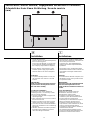
Installation
Installazione
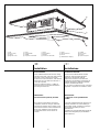
Unit installation
Insert 4 M8 threaded rods into the celling.
Introduce the other end of the rods through
the slots of unit suspension brackets.
Position the shock absorbers, add washers
and screw the nuts down until the unit is
correctly suported.
If there is sufficient space, a rubber or
neoprene sheet can be placed between
the ceiling and the unit.
IMPORTANT:
The unit must be perfectly levelled.
Once all these operations have been
completed, the false ceiling to hide hide
unit may be installed, but a register cover
must be left below for future maintenance.
Grills of an adequate size should be
incorporated in the unit for return air
suction.
a Unit
b False ceiling
c Ceiling
d Register cover
Installazione dell’unità
Inserire 4 tiranti filettati M8 nel soffitto.
Introdurre l’altra estremità dei tiranti
attraverso le asole delle staffe di
appensione esistenti sui lati dell’unità.
Posizionare gli antivibranti, aggiungere le
rondelle ed avvitare i dadi fino a quando
l’unità è correttamente fissata.
Se c’é spazio a sufficienza, porre uno strato
di gomma o neoprene tra il soffitto e l’unità.
IMPORTANTE:
L’unità deve essere perfettamente
livellata
Una volta completate queste operazioni, é
possibile installare un controsoffitto per
nascondere l’unità; prevedere comunque
un pannello rimovibile per future
manutenzioni.
Prevedere nel controsoffitto delle griglie di
dimensione adeguata per permettere la
ripresa dell’aria.
a Unité
b Faux plafond
c Plafond
d Couverture amovible
a
Unità
b
Controsoffitto
c
Soffitto
d
Copertura removibile
a
Gerät
b
Zwischendecke
c
Decke
d
Abnehmbarer Zugang
a Unidad
b Falso techo
c Forjado
d Tapa de registro
a
b
c
d
La pagina sta caricando ...

20
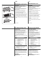
Condensate drainage
All units are provided with an internal
condensate drain pan which incorporates a
drainage tube 20 mm external Ø (009, 012,
018) and 25 mm (024, 028, 036, 048, 060).
A tube for evacuating condensates must
therefore be provided.
The recommendations below must be
followed in all cases:
• Use galvanizad steel, copper or plastic
piping.
Do not used ordinary garden hose.
• Use a material that guarantees perfect
watertightness on the drainage pipe.
• If rigid material has been used for the
drainage, it is necessary to provide some
kind of elastic coupling in the drainage
line to absorb possible vibrations.
• The drainage line should always be
below the connextion itself, and should
also slope to facilitate drainage.
• If temperatures below freezing are
expected in the unit surroundings, the
drain tube should be protected against
the possible formation of ice.
To do so, a heating wire should be
installed in the drain connection.
Which should be independent from the
unit power supply, and come into
operation before the temperature drops
below freezing point.
WARNING:
No drillholes should be made in the
base of the unit, since the drain pans
may be perforated.
Ductwork
The ductwork dimensions should be
determined in accordance with the air flow
circulating through it and with the available
static pressure of the unit. This data
appears in the correspondign Technical
Documentation.
Various suggestions are made herebelow,
regarding the layout and design of the said
doctwork.
• Whatever type of duct is used, it should
not be made of materials which are
flammable, or which give off toxic gases
in the event of a fire. The internal
surfaces should be smooth, and not
conteminate the air which passes
through.
• At the points where the duct joins with
the unit, it is advisable to use a flexible
connection which absorbs vibration and
prevents the transmission of noise inside
the ductwork.
• Bends should be avoided as much as
possible near the unit outlet. If
unavoidable, they should be as slight as
possible, and internal deflectors should
be used when the duct is of large
dimensiones.
IMPORTANT:
Duct calculation and design must be
effected by a qualified technician.
Installation
Installazione
Drenaggio condensa
Tutte le unità sono fornite di bacinella
scarico condensa con tubo di drenaggio
Ø esterno 20 mm (009, 012, 018) e
25 mm (024, 028, 036, 048, 060).
Installare quindi una tubazione per
l’evacuazione della condensa.
Seguire tuttavia le seguenti raccomandazioni:
• Utilizzare tubazioni di acciaio zincato,
di rame o plastica trasparente.
Non utilizzare normali tubi da
giardinaggio.
• Utilizzare materiale che garantisca una
perfetta tenuta nei collegamenti del tubo
di scarico.
• In caso di utilizzo di materiale rigido per
lo scarico prevedere alcuni collegamenti
elastici per assorbire eventuali vibrazioni
dell’unità.
• La linea di drenaggio deve essere
sempre al di sotto del collegamento
stesso, con una pendenza per agevolarne
il deflusso.
• Se si prevedono temperature al di sotto
dello zero intorno all’unità, è necessario
proteggere il tubo di scarico dalla
possibile formazione di ghiaccio.
In questo caso è necessario prevedere
un cavo di riscaldamento sul collegamento
di scarico, che deve essere indipendente
dall’alimentazione dell’unità ed entrare in
funzionamento prima che la temperature
scenda al di sotto del punto di
congelamento.
ATTENZIONE:
Evitare di trapanare la base dell’unità,
poichè si potrebbe bucare la bacinella.
Canalizzazione
Determinare le dimensioni dei canali in
accordo con la portata d’aria richiesta e la
pressione statica disponibile dell’unità.
Questi dati appaiono sulla
documentazione tecnica corrispondente.
Si consiglia di seguire le seguenti
raccomandazioni:
• Qualunque sia il tipo di canale utilizzato,
non deve essere di materiale infiammabile,
che producano gas tossici in caso di
incendio. Le superfici interne devono
essere liscie e non contaminare l’aria
che vi passa attraverso. Si consiglia di
usare canali in acciaio zincato, adeguata-
mente isolati, per evitare la formazione di
condensa e perdite termiche.
• Per unire i canali all’unità, é consigliabile
l’utilizzo di collegamenti flessibili che
assorbano le vibrazioni e prevengano la
trasmissione di rumore all’interno della
canalizzazione e permettano l’accesso
all’unità.
• Evitare nel limite del possibile curve
vicino alla mandata d’aria dell’unità. Se
così non fosse, il raggio di curvatura
deve essere il più ampio possibile;
utilizzare deflettori interni quando il
canale é di grandi dimensioni.
IMPORTANTE:
Il progetto ed il calcolo dei canali deve
essere fatto da tecnici qualificati.
La pagina sta caricando ...

22
VERY IMPORTANT:
To prevent electrical shock or
equipment damage, make sure the
power supply sectioners are open
before electrical connections are made.
If this action is not taken, personal
injury may occur.
Fiel wiring must comply with valid codes.
Take special care when making the earth
connection.
Voltage to unit must be within ±10% of
voltage and ±10% of current as indicated
on nameplate.
Contact local power company for
correction of improper line voltage.
Check these before selecting supply wiring
fuses an controls.
IMPORTANT:
Operation of unit on improper line
voltage constitutes abuse and is not
covered by Carrier warranty.
IMPORTANT:
• The mains supply connecting cable
must be H07 RN-F type (or higher),
synthetic rubber insulation with
Neoprene coating, according to EN
60335-2-40 and HD277.S1 codes.
• Make the main electrical connection
for the assembly via the outdoor unit.
Consult the wiring diagram sent with
the outdoor unit.
• To effect the unit power supply (wire
inlet, conductor section, protections,
etc..), consult the Electrical Data
Table, the wiring diagram sent with
the unit and the standards in force
affecting the installation of air
conditioning equipment.
VERY IMPORTANT:
The installer should place protection
elements in the line according to the
legislation in force.
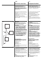
a Indoor unit
b Outdoor unit
c Control
d Main power supply
(field wiring)
e Connecting cable, indoor-outdoor units
(field wiring).
f Connecting cable indoor unit - control
(field wiring).
Electrical connections
Collegamenti elettrici
ATTENZIONE:
Per evitare pericolose scariche
elettriche o danni all’unità, assicurarsi
che i contatti elettrici siano aperti prima
di effettuare i collegamenti stessi.
L’aimentazione elettrica deve corrisponde-
re ai dati contenuti sulla targhetta.
Fare particolare attenzione quando si
compie la messa a terra.
La tensione fornita all’unità deve restare
entro il ±10% della tensione e il ±10%
della corrente come indicato sulla
targhetta.
Contattare la compagnia elettrica per
correzioni a linee di tensione non adeguate.
Controllare questi punti prima di scegliere i
fusibili.
ATTENZIONE:
L’avviamento dell’unità con una
tensione errata fa decadere la garanzia
Carrier.
IMPORTANTE:
• Il cavo elettrico di alimentazione deve
essere di tipo H07 RN-F (o superiore)
con isolamento in gomma sintetica e
guaina in policloroprene, in accordo
alle norme EN 60335-2-40 e HD277.S1.
• Il collegamento alla rete elettrica deve
essere eseguito attraverso l’unità
esterna.
Consultare lo schema elettrico
allegato all’unità esterna.
• Per eseguire i collegamenti elettrici
dell’unità (entrata dei cavi, sezione dei
conduttori, protezioni…), consultare
la tabella dei dati elettrici, lo schema
elettrico allegato all’unità e rispettare
le norme in vigore per l’installazione
di apparecchi per la climatizzazione.
IMPORTANTISSIMO:
L’installatore deve apporre tutti gli
elementi di protezione secondo la
legislazione in vigore
a
Unità interna
b
Unità esterna
c
Comando
d
Alimentazione elettrica principale
(a cura dell’installatore).
e
Cavo di collegamento unità interna -
unità esterna (a cura dell’installatore).
f
Cavo di collegamento unità interna -
comando (a cura dell’installatore).
IMPORTANT:
• Make ground connection prior to any
other electrical connections.
• Make electrical connections between
units prior to proceeding to mains supply
unit connection.
• Ensure that mains supply connection is
made through a switch that disconnects
all poles, with contact gap of a least 3 mm.
NOTE:
• All field electrical connection are the
responsibility of the installer.
IMPORTANTE:
• Eseguire il collegamento di messa a
terra prima dei collegamenti elettrici.
• Effettuare prima il collegamento elettrico
tra le due unità e successivamente il
collegamento alla rete di alimentazione.
• Assicurarsi che il collegamento alla rete
elettrica sia effettuato attraverso un
interruttore onnipolare con apertura dei
contatti di almeno 3 mm.
NOTA:
• Collegamenti elettrici a carico
dell’installatore.
a
e
c
f
b
d
La pagina sta caricando ...
La pagina sta caricando ...

25
C
G
P
B
2 3N N Y O
W2
V
1
V
2
V
3
V
4
40 41
1L
a
C G P
b
Legenda morsettiera tutti i modelli solo
raffrescamento
a
Unità interna
Terra
L Linea (fase) alimentazione elettrica
N Neutro, alimentazione elettrica
R Linea (fase) collegamento verso l’unità esterna
C Neutro, collegamento verso l’unità esterna
Y Consenso compressore
O Comando valvola inversione (solo pompa di
calore)
W2 Comando ventilatore esterno
S Segnale termostato di fine sbrinamento
V1, V2, V3, V4 Velocità ventilatore interno
40, 41 Comando resistenze elettriche
1, 2, 3 Comando Room Controller
b
Room Controller
P Alimentazione (rosso)
G Terra (nero)
C Segnale (bianco)
c
Alimentazione: 230V ~ 50Hz
A Cavo alimentazione sistema
(a cura dell’installatore)
B Cavo di collegamento verso l’unità esterna
(a cura dell’installatore)
C Interruttore generale
D Fusibile magnetotermico
N.B.: Per la corretta alimentazione del sistema riferirsi
al manuale d’installazione dell’unità esterna.
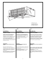
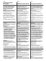
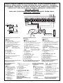
Electric connection diagrams for cooling only units /
Schemi collegamenti elettrici
unità solo raffrescamento
/ Schémas de câblage des unités froid seul /
Schaltpläne
für Kühlgeräte
/ Diagramas de conexiones eléctricas para las unidades de sólo refrigeración
Outdoor unit /
Unità esterna
/ Unité extérieure /
Außengerät
/ Unidad exterior
38BCS009 - 38BCS012
Indoor unit /
Unità interna
/ Unité intérieur /
Innengerät
/ Unidad interior
40SMC009N - 40SMC012N
A
B
10
80
10
100
Terminal block legend for cooling only units
a Indoor unit
Earth
L Live power supply
N Neutral power supply
R Power supply connection to outdoor unit
C Neutral, connection to outdoor unit
Y Compressor interlocking contact
O Reversing valve control (Heat pump only)
W2 Outdoor fan signal
S Thermostat end of defrosting signal
V1, V2, V3, V4 Indoor fan speed
40, 41 Electric heater control
1, 2, 3 Room Controller control
b Room Controller
P Power supply (red)
G Earth (black)
C Signal (white)
c Power supply: 230V ~ 50Hz
A Mains supply connecting cable (field wiring).
B Connecting cable to outdoor unit
(field wiring)
C Main switch
D Magnetothermal fuse
NOTE: For a correct power supply, see outdoor
unit installation instructions.
Légende plaque à bornes tous les modèles seul froid
a Unité intérieure
Terre
L Courant secteur
N Neutre alimentation secteur
R
Courant secteur de connexion vers l’unité extérieure
C Neutre, connexion vers l’unité extérieure
Y Contact d’asservissement du compresseur
O Commande du robinet inverseur (pompe à
chaleur seul)
W2 Signal ventilateur extérieur
S Signal thermostat fin dégivrage
V1, V2, V3, V4 Vitesse ventilateur intérieur
40, 41
Commande résistances électriques
1, 2, 3 Commande Room Controller
b Room Controller
P Tension d’alimentation (rouge)
G Terre (noir)
C Signal (blanc)
c Tension d’alimentation: 230V ~ 50Hz
A Câble de l’alimentation secteur
(à fournir par l'installateur)
B Câble de connexion vers l’unité extérieure
(à fournir par l'installateur)
C Disjoncteur principal
D Fusible magnétothermique
NOTE: Pour assurer la correcte alimentation du
système, se rapporter aux instructions
d’installation de l’unité extérieure
Legende Klemmleiste für alle
Modelle Kühlgeräte
a
Innengerät
Erde
L Netzversorgungsleitung
N Nulleiter, netzversorgung
R Leitung (Phase), Anschluss
an das Außengerät
C Nullleiter, Anschluss an
das Außengerät
Y Verdichter-
Verriegelungskontakt
O Umkehrventil-Regelung
(nur Wärmepumpe)
W2 Signal des
Außenventilators
S Signal des Thermostats:
Ende Enteisung
V1, V2, V3, V4
Geschwindigkeit
Innenventilator
40, 41
Steuerung elektrische Widerstände
1, 2, 3
Steuerung Room Controller
b
Room Controller
P Stromversorgung (rot)
G Erde (schwarz)
C Signal (weiß)
c
Stromversorgung: 230V ~ 50Hz
A Netzversorgungs-Verbindungskabel
(field wiring)
B Verbindungskabel zum Außengerät
(field wiring)
C Hauptschalter
D Magnetothermische Sicherung
Hinweis: Zur korrekten
Systemsversorgung auf die
Installationsanweisung des Außengerät
Bezug nehmen.
Leyenda tablero de bornes para todos
los modelos de sólo refrigeración
a Unidad interior
Tierra
L Línea suministro principal
N Neutro, suministro principal
R Línea (fase) conexión hacia
la unidad exterior
C Neutro, conexión hacia la
unidad exterior
Y Contacto enclavamiento del
compresor
O Control de la válvula de
inversión (sólo bomba de
calor)
W2 Señal del ventilador exterior
S Señal termostato de final de
deshelado
V1, V2, V3, V4
Velocidad ventilador interno
40, 41 Mando resistencias eléctricas
1, 2, 3 Mando Room Controller
b Room Controller
P Suministro de potencia (rojo)
G Tierra (negro)
C Señal (blanco)
c Suministro de potencia : 230V ~ 50Hz
A Cable de suministro principal de
inter-conexión
(a suministrar por el instalador)
B
Cable de conexión hacia la unidad exterior
(a suministrar por el instalador)
C Interruptor principal
D Fusible termomagnético
NOTA: Para la correcta alimentación del
sistema, consúltese el manual de
instalación de la unidad exterior.

26
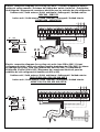
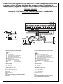
Electric connection diagrams for heat pump units /
Schema collegamento elettrico unità
a pompa di calore
/ Schémas de câblage des pompes à chaleur /
Schaltpläne für
Wärmepumpen
/
Diagrama de conexiones eléctricas para las unidades de bomba de calor
Outdoor unit /
Unità esterna
/ Unité extérieure /
Außengerät
/ Unidad exterior
38BH009 - 38BH012
Indoor unit /
Unità interna
/ Unité intérieur /
Innengerät
/ Unidad interior
40SMC009N - 40SMC012N
C
G
P
A
B
2 3N N Y O
W2
V
1
V
2
V
3
V
4
40 41
1L
a
C G P
b
C D
c
Legenda morsettiera tutti i modelli a pompa di calore
a
Unità interna
Terra.
L Linea (fase) alimentazione elettrica.
N Neutro, alimentazione elettrica.
R Linea (fase) collegamento verso l’unità esterna.
C Neutro, collegamento verso l’unità esterna.
Y Consenso compressore.
O Comando valvola inversione (solo pompa di calore).
W2 Comando ventilatore esterno.
S Segnale termostato di fine sbrinamento.
V1, V2, V3, V4Velocità ventilatore interno
40, 41 Comando resistenze elettriche
1, 2, 3 Comando Room Controller
b
Room Controller
P Alimentazione (rosso)
G Terra (nero)
C Segnale (bianco)
c
Alimentazione: 230V ~ 50Hz
A Cavo alimentazione sistema
(a cura dell’installatore)
B Cavo di collegamento verso l’unità esterna
(a cura dell’installatore)
C Interruttore generale
D Fusibile magnetotermico
N.B.:
Per la corretta alimentazione del sistema riferirsi al
manuale d’installazione dell’unità esterna.
A
B
10
80
10
100
Terminal block legend for all heat pump units
a Indoor unit
Earth
L Live power supply
N Neutral power supply
R Power supply connection to outdoor unit
C Neutral, connection to outdoor unit
Y Compressor interlocking contact
O Reversing valve control (Heat pump only)
W2 Outdoor fan signal
S Thermostat end of defrosting signal
V1, V2, V3, V4 Indoor fan speed
40, 41 Electric heater control
1, 2, 3 Room Controller control
b Room Controller
P Power supply (red)
G Earth (black)
C Signal (white)
c Power supply: 230V ~ 50Hz
A Mains supply connecting cable (field wiring).
B Connecting cable to outdoor unit
(field wiring)
C Main switch
D Magnetothermal fuse
NOTE:
For a correct power supply, see outdoor unit installation
instructions.
La pagina sta caricando ...

28
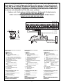
Refrigerant line connection
(Flare connnections)
Collegamento linea refrigerante
(attacchi a cartella)
For refrigerant tubes use seamless,
insulated refrigeration grade tube, (Cu DHP
type according to ISO1337), degreased and
deoxidized, suitable for operating pressures
of at least 4200 kPa and for burst pressure
of at least 20700 kPa. Under no circumstances
must sanitary type copper pipe be used.
N.B.: Gas extra-charge: outdoor unit
38YY060G903, add 450 g.
Tubing Min. nominal
Tightening
diameter thikness torque
mm (inches) mm Nm
6.35 (1/4") 0.80 18
9.52 (3/8") 0.80 42
12.70 (1/2") 0.80 55
15.87 (5/8") 1.00 65
19.05 (3/4") 1.15 100
Insufficient tightening torque will cause gas
leaks.
Overtightening the fittings will damage the
tube flaring and cause gas leaks.
Per le tubazioni utilizzare tubo di rame isolato,
(tipo Cu DHP in accordo alle norme ISO 1337),
del tipo senza saldatura, sgrassato e disossidato
,
adatto per pressioni di lavoro di almeno 4200 kPa
e per una pressione di scoppio di almeno
20700 kPa. Non è assolutamente adatto il
tubo di rame per applicazioni idrosanitarie.
N.B.: Extra carica refrigerante: unità
esterna 38YY060G903 aggiungere 450 g.
Diametro Spessore min. Coppia
tubazione nominale
serraggio
mm (pollici) mm Nm
6,35 (1/4") 0,80 18
9,52 (3/8") 0,80 42
12,70 (1/2") 0,80 55
15,87 (5/8") 1,00 65
19,05 (3/4") 1,15 100
Con coppia di serraggio insufficiente, ci sarà
una fuga di refrigerante dalla connessione.
Con coppia di serraggio eccessiva, si
rovinerà la svasatura del tubo di rame, con
conseguente perdita di refrigerante.
A Unidad exterior
B A suministrar por el
instalador
C 40SMC---N
d Tuerca de la toma de
presión.
e Tuerca de la válvula de 3
vías.
f Tuerca bocarda. (Lado
unidad exterior).
g Cuerpo de la conexión
flare.
h Línea de líquido o
aspiración. (Suministra el
instalador)
i Tuerca bocarda
acoplamiento
evaporadora.
A Outdoor unit
B Field installed
C 40SMC---N
d Pressure needle nut.
e 3 way valve nut.
f Flared nut. (Outdoor unit
side).
g Flare connection body.
h Liquid or suction line.
(Supplied by the
installer).
i Evaporator coupling flare
nut.
A
Unità esterna
B
A cura dell’installatore
C
40SMC---N
d
Bocchettone presa
pressione
e
Bocchettone valvola a tre
vie
f
Bocchettone a cartella
(lato unità esterna)
g
Corpo della connessione
FLARE
h
Linea liquido o di
aspirazione (fornito
dall’installatore)
i
Bocchettone
accoppiamento
evaporatore
A Unité extérieure
B à fournir par l’installateur
C 40SMC---N
d Ecrou de la prise de
pression
e Ecrou vanne trois voies
f Raccord Flare (côté unité
extérieure)
g Corps du raccord Flare
h Conduite liquide ou
d’aspiration (fournie par
l’installateur)
i Raccord Flare de
l’évaporateur
A
AuBengerät
B
Bauseitige Verdrahtung
C
40SMC---N
d
Druckanschluß-Mutter
e
Mutter des 3-Wege-
Ventils
f
Bördelmutter
(Außengerät-Seite)
g
Bördelanschlußteil
h
Flüssigkeits- oder
Sauggasleitung (vom
Installateur beizustellen)
i
Verdampferkupplung-
Bördelmutter
ifgh
de
BAC
La pagina sta caricando ...

30
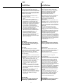
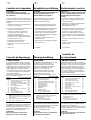
Maintenance and service
ATTENTION:
Before performing any service or
maintenance operations, turn OFF the
main power switch.
In order to obtain maximum performance,
special attention should be paid to the
following points:
• Inspect and clean the outdoor unit,
especially the heat exchanger coil.
• Ensure that all rubber and insulating
joints are in good condition.
• Check and clean condenser drain pan of
the indoor unit; the same check must be
made for the heat pump outdoor units.
• Check tightness of electric connections.
• Clean or replace the air filter of the indoor
unit.
a Air filter.
Manutenzione e cura
ATTENZIONE:
Prima di iniziare qualunque operazione
di pulizia o di manutenzione togliere
l’alimentazione elettrica.
Per ottenere ottime prestazioni, si consiglia
di prestare particolare attenzione ai
seguenti punti:
• Ispezionare e pulire l'unità esterna ed in
particolare la batteria di scambio
termico.
• Assicurarsi che i giunti in gomma e
isolanti siano in buone condizioni.
• pulire e liberare da eventuali ostruzioni la
bacinella e lo scarico della condensa
dell'unità interna; eseguire gli stessi
controlli sulle unità esterne a pompa di
calore.
• controllare il serraggio dei contatti
elettrici.
•
pulire o sostituire il filtro dell'aria dell'unità
interna.
a
Filtro aria.
Troubleshooting chart
Alarm code
A diagnostic system is contained in the
electronic card to “check” the system
integrity. When the diagnostic system is
under alarm, the red LED installed onto the
main card flashes as indicated below:
• 0.5 sec. ON and 0.5 sec. OFF.
• The number of flashes depends on the
error that has been detected.
Not all of the errors can be reset (see table
below).
Error
Error
Resettable
code *
2 Condensation discharging pump NO
3 Air temperature sensor YES
4 Internal battery temp. sensor YES
5 External battery temp. sensor YES
6** Dirty filters YES
7 Outdoor unit error YES
8 Low voltage YES
9 Compressor malfunction ***
10 EEPROM YES
11 Serial number YES
12 Address/zone number YES
13 Gas flow distributor YES
*NO: Turn off power supply to the system, check
and repair, if necessary. Turn on power.
YES: Check
** If this diagnostic system is enabled.
*** YES, for the first 4 errors.
A series of possible faults is related below,
as well as the probable causes and suggested
solutions. However, in the event of a unit
malfunction, it is advisable to disconnect
the power supply and ascertain the cause.
ATTENTION:
Most operations must be carried out by
skilled personnel.
Ricerca inconvenienti
Codice di allarme
La scheda elettronica contiene una
diagnostica interna che “sorveglia”
l’integrità del sistema.
Quando la diagnostica va in allarme il LED
rosso a bordo della scheda elettronica
principale lampeggia nel seguente modo:
• 0,5 secondi acceso e 0,5 secondi spento
.
• Il numero dei lampeggi varia in funzione
dell’errore diagnosticato.
Non tutti gli errori sono riprestinabili (vedi
tabella sottostante).
Codice
Errore
Riprestinabile
errore *
2 Pompa scarico condensa NO
3 Sensore temperatura aria SI
4 Sensore temp.batteria interna SI
5 Sensore temp.batteria esterna SI
6** Filtri sporchi SI
7 Errore unità esterna SI
8 Tensione bassa SI
9 Malfunzionamento compressore ***
10 EEPROM SI
11 Numero seriale SI
12 Indirizzo/numero di zona SI
13 Gas flow distributir (GFD) SI
*NO: togliere tensione al sistema, verificare e
riparare se necessario. Rialimentare il sistema.
SI: Verificare.
** Se è attiva questa diagnostica.
*** SI, per i primi 4 errori.
Di seguito sono nominati alcuni
inconvenienti possibili, con la causa
probabile e la soluzione suggerita.
In ogni caso è consigliabile togliere
l’alimentazione e accertare la causa.
ATTENZIONE:
Molte operazioni sono da far eseguire a
personale qualificato.
a
a
La pagina sta caricando ...

32
Troubleshooting chart
Symptoms / Cause / REMEDY
Unit does not start
• No power supply:
CHECK.
• Main switch open:
CLOSE SWITCH.
• Current wires cut:
CEPAIR OR REPLACE
(
BY SKILLED PERSONNEL
).
• Fuses blown: REPLACE AND CHECK
CONSUMPTIONS.
• Protector tripped:
RESET AS DESCRIBED.
• Thermostat wrongly adjusted:
SELECT A MORE SUITABLE TEMPERATURE.
Unit provides less cooling or heating
than normal
• Dirty air filter:
CLEAN FILTER.
• Wrongly adjusted or faulty thermostat:
SELECT A MORE SUITABLE TEMPERATURE, OR
REPLACE THERMOSTAT.
Unit operates continuously, or stops
and starts very frequently (by skilled
personnel)
.
• Refrigerant loss: CHECK AND ADD THE
NECESSARY QUANTITY (R-410A).
• Faulty compressor (Outdoor unit):
REPLACE COMPRESSOR.
• Faulty compressor contactor (Outdoor
unit):
CHANGE CONTACTOR.
Unusual noises or strange vibrations
(by skilled personnel)
.
• Fan motor fixtures loose: TIGHTEN FIXTUR
• Badly adjusted panels: ADJUST PROPERLY
• Unit wrongly installed: CHECK INSTALLATION
• A foreign object, tool, etc, has got into
the fan:
REMOVE THE FOREIGN OBJECT
Fan and motor not operate (by skilled
personnel)
.
• Faulty motor or capacitor: REPLACE
• Loose connections:
CHECK AND TIGHTEN PROPERLY
Final recommendations
All units undergo strict Quality Control
testing before leaving the factory.
Whatsmore, all the elements included,
such as the control system, electrical
equipment, etc., are qualified by our
Quality Control Department, and laboratory
tested in the harshest possible conditions.
Nevertheless, after leaving the factory, it is
possible that these elements may be
demaged due to causes beyond our
control. In an event, and if the unit fails to
operate correctly: the user should not
manipulate any of the internal elements.
In the event that inspection and repair
work is required, it should be left to a
specialized technician.
All recommendations concerning unit
installation are intended to be orientative.
The installing firm should do the job
according to the characteristics of the
project, and in all events comply with the
official rulling for air conditioning and
refrigeration installations.
IMPORTANT:
The manufacturer declines all
responsability for malfunction resulting
from abuse.
Ricerca inconvenienti
Anomalia / Causa /
RIMEDIO
L'unità non funziona
•Mancanza di alimentazione elettrica:
VERIFICARE
.
•
Interruttore principale aperto:
CHIUDERE
L
’
INTERRUTTORE
.
•Cavi della corrente tagliati:
RIPARARE
O
SOSTITUIRE
(
A
CURA
DEL
PERSONALE
QUALIFICATO
).
•Fusibili bruciati:
SOSTITUIRE
E
VERIFICARE
GLI
ASSORBIMENTI
.
•Una protezione è intervenuta:
RISTABILIRE
COME
DESCRITTO
.
•Termostato regolato erroneamente:
SELEZIONARE
UNA
TEMPERATURA
PIÙ
ADEGUATA
.
L’unità raffresca o riscalda in modo
insufficiente
•Filtro aria sporco:
PULIRE
IL
FILTRO
.
•Termostato regolato male o difettoso:
SELEZIONARE
UNA
TEMPERATURA
PIÙ
ADEGUATA
O
SOSTITUIRE
TERMOSTATO
.
L’unità funziona in continuazione, o parte
e si ferma frequentemente (verifiche a
carico del personale qualificato)
•Perdita di refrigerante:
VERIFICARE
ED
AGGIUNGERE
LA
QUANTITÀ
NECESSARIA
(
R
-
410A
).
•Compressore difettoso (Unità esterna):
SOSTITUIRE
COMPRESSORE
.
•Contattore compressore dfettoso (Unità
esterna):
CAMBIARE
CONTATTORE
.
Rumori insoliti e strane vibrazioni
(verifiche
a carico del personale qualificato)
•Collegamenti ventilatore allentati:
STRINGERE
I
COLLEGAMENTI
•Pannelli posizionati non correttamente:
SISTEMARE
•Errata installazione dell’unità:
VERIFICARE
L
’
INSTALLZIONE
•Corpi estranei, attrezzi etc. nel ventilatore:
RIMUOVERE
IL
CORPO
ESTRANEO
Il ventilatore ed il motore non funzionano
(verifiche a carico del personale qualificato):
•Condensatore o motore difettosi:
SOSTITUIRE
.
•Collegamenti alletati:
CONTROLLARE
E
SERRARE
ADEGUATAMENTE
.
Raccomandazioni finali
Tutte le unità fornite sono state sottoposte
ai test del Controllo Qualità. Inoltre,tutte le
parti incluse, come ad esempio il sistema di
controllo, gli apparecchi elettrici ecc…, sono
stati verificati dalla Divisione Controllo
Qualità del costruttore e controllati in
laboratorio sottoponendoli alle condizioni
più gravose. Tuttavia è possibile che le parti
fornite possano risultare danneggiate per
cause non dovute al costruttore. In questo
caso, e nel caso in cui l’unità non funzionasse
correttamente: si consiglia di non manipolare
nessuno degli elementi interni. Nel caso
in cui fosse necessario un controllo o
una riparazione, questa operazione dovrà
essere effettuata da un tecnico specializzato,
o la garanzia sarà invalidata. I suggerimenti
riguardanti l’installazione dell’unità devono
essere considerati come orientativi. Spetta
alla ditta installatrice il compito di installare
l’impianto in base alle caratteristiche del
progetto e nel rispetto della regolamentazione
sull’installazione degli impianti di climatizzazione.
IMPORTANTE:
Il costruttore non si assume alcuna
responsabilità in caso di danni dovuti a
manomissioni o uso improprio dell’unità.
La pagina sta caricando ...

34
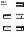
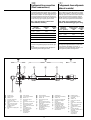
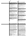
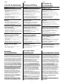
Fan diagrams
Diagrammi ventilatore
40SMC009N
40SMC024N
1- Velocídad super alta
(opcional)
2- Velocídad alta
3- Velocídad media
4- Velocídad baja
e Caudal de aire (l/s)
1- Super Hochgeschwindigkeit
(option)
2- Hochgeschwindigkeit
3- Mittelgeschwindigkeit
4- Niedriggeschwindigkeit
e
Luftleistung (l/s)
1- Super haute vitesse
(option)
2- Haute vitesse
3- Moyenne vitesse
4- Basse vitesse
e Débit d’air (l/s)
1- Super alta velocità
(opzionale)
2- Alta velocità
3- Media velocità
4- Bassa velocità
e
Portata d’aria (l/s)
1- Super high speed
(optional)
2- High speed
3- Medium speed
4- Low speed
e Air flow (l/s)
e
40SMC012N
40SMC018N
Pa
Pa
100
90
80
70
60
50
40
30
20
10
0
70 90 110 130 150 170 180 190
1
2
3
4
100
90
80
70
60
50
40
30
20
10
0
140 160 180 200 220120100
1
2
3
4
100
90
80
70
60
50
40
30
20
10
0
120 150 200 240
1
2
3
4
100
90
80
70
60
50
40
30
20
10
0
170 200 250 400300 350 410
1
2
3
4
ee
e
Pa
Pa

35
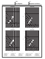
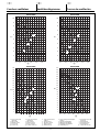
Curvas de ventilación
Ventilatordiagramme
Courbes ventilateur
40SMC036N
e
e
1- Velocídad super alta
(opcional)
2- Velocídad alta
3- Velocídad media
4- Velocídad baja
e Caudal de aire (l/s)
1- Super Hochgeschwindigkeit
(option)
2- Hochgeschwindigkeit
3- Mittelgeschwindigkeit
4- Niedriggeschwindigkeit
e
Luftleistung (l/s)
1- Super haute vitesse
(option)
2- Haute vitesse
3- Moyenne vitesse
4- Basse vitesse
e Débit d’air (l/s)
1- Super alta velocità
(opzionale)
2- Alta velocità
3- Media velocità
4- Bassa velocità
e
Portata d’aria (l/s)
1- Super high speed
(optional)
2- High speed
3- Medium speed
4- Low speed
e Air flow (l/s)
40SMC028N
Pa
Pa
Pa
Pa
100
90
80
70
60
50
40
30
20
10
0
220 250 300 400 450350
1
2
3
4
100
90
80
70
60
50
40
30
20
10
0
300 350 400 450 500 550
1
2
3
4
190
90
40
30
20
10
0
300 400 500 600 700 800 850 900
180
170
160
150
140
130
120
110
100
80
70
60
50
200
1
2
3
4
190
90
40
30
20
10
0
300 400 500 600 700 800 900
200
180
170
160
150
140
130
120
110
100
80
70
60
50
1
2
3
4
e
40SMC048N
40SMC060N
e
La pagina sta caricando ...
-
 1
1
-
 2
2
-
 3
3
-
 4
4
-
 5
5
-
 6
6
-
 7
7
-
 8
8
-
 9
9
-
 10
10
-
 11
11
-
 12
12
-
 13
13
-
 14
14
-
 15
15
-
 16
16
-
 17
17
-
 18
18
-
 19
19
-
 20
20
-
 21
21
-
 22
22
-
 23
23
-
 24
24
-
 25
25
-
 26
26
-
 27
27
-
 28
28
-
 29
29
-
 30
30
-
 31
31
-
 32
32
-
 33
33
-
 34
34
-
 35
35
-
 36
36


Carrier 40SMC036N Guida utente
- Categoria
- Condizionatori d'aria a sistema split
- Tipo
- Guida utente
in altre lingue
- English: Carrier 40SMC036N User guide
- français: Carrier 40SMC036N Mode d'emploi
- español: Carrier 40SMC036N Guía del usuario
- Deutsch: Carrier 40SMC036N Benutzerhandbuch
Documenti correlati
Altri documenti
-
Kampmann TOP unit heaters Guida d'installazione
-
 Olimpia Splendid SHERPA 4 Guida d'installazione
-
Rowenta VITALITY LINENDRY Manuale del proprietario
-
Saunier Duval SDH 31-061 M2NW Manuale del proprietario
-
Vaillant VAM 6-085 W4N Manuale utente
-
Equation WAP-357DZ-35R Manuale del proprietario
-
-
Vaillant VAI 6-025 WN Guida d'installazione
-
-
