
Matrix-1000™
QUICK REFERENCE GUIDE

MATRIX-1000™ QUICK GUIDE
2
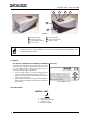
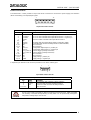
Figure A
Reading Window
A
uxiliary Interface
Main Tx LED
Good Read LED
Main/Auxiliary Interface
1
2
4
5
3
6
7
External Trigger LED
Power On LED
NOTE
For further details on product installation, see the complete Installation Manual available on the
CD included with this product.
Compliance:
- This product is intended to be installed by Qualified Personnel only.
- This product is intended to be connected to a UL Listed
Computer which supplies power directly to the reader or a
UL Listed Direct Plug-in Power Unit marked LPS or
“Class 2”, rated 10 to 30 V, minimum 1 A.
- In order to meet the EMC requirements:
• connect reader chassis to the plant earth ground by
means of a flat copper braid shorter than 100 mm;
• connect the main interface cable shield to pin 1 of the
reader 25-pin connector;
• use two clip-on ferrite sleeves (type Stewart 28A2029-
0A0) on the main interface cable near the reader 25-
pin connector;
TO EN 60825-1:2001
Model Description:
MATRIX - 10X1
Optics
2 = High Density (HD)
3 = Standard Density (STD)
4 = Low Density (LD)
5 = Medium Range (MR)
1
4 5
3
6
7
2

MATRIX-1000™ QUICK GUIDE
3
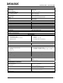
ELECTRICAL FEATURES
Power
Supply Voltage 10 to 30 Vdc
Power Consumption 4 W max.; 2.5 W typical
Communication Interfaces
Main - RS485 half-duplex
Auxiliary - RS232
2400 to 115200 bit/s
2400 to 115200 bit/s
Input
External Trigger
Opto-coupled and polarity insensitive
Output
OUT3 Opto-coupled
OPTICAL FEATURES
Image Sensor Matrix CCD
Image Format VGA (640x480)
Lighting System LED array
Wavelength 630 ~ 670 nm
Max LED Output Power 0.7 mW
LED Safety Class Class 1 to EN60825-1
USER INTERFACE
LED Indicators PWR, TRIG, READ, COM
SOFTWARE FEATURES
Readable Code Symbologies
1-D and stacked
• PDF417 Standard • Codabar
• Code 128 (EAN 128) • Code 93
• Code 39 (Standard and Full ASCII)
• Interleaved 2 of 5
• EAN-8/13 - UPC-A/E
(including Addon 2 and Addon 5)
2-D
• Data Matrix ECC 200 • QR Code
POSTAL
• Australia Post • PLANET
• Royal Mail 4 State Customer • POSTNET, POSTNET (+BB)
• Kix Code • POSTNET + PLANET, POSTNET (+BB) + PLANET
• Japan Post
Operating Mode ONE-SHOT, CONTINUOUS, PHASE MODE
Configuration Mode By means of VisiSet™ configuration software
Parameter Storage Permanent memory (Flash)
MECHANICAL FEATURES
Dimensions 121 x 73 x 57 mm (4.76 x 2.87 x 2.24 in.)
Weight 330 g.
Material Magnesium alloy
ENVIRONMENTAL FEATURES
Operating Temperature
0 to 40 °C (32 to 104 °F)
Storage Temperature
-20 to 70 °C (-4 to 158 °F)
Max. Humidity 90% non condensing
Vibration Resistance IEC 68-2-6 test FC 1.5 mm;
10 to 55 Hz; 2 hours on each axis
Shock Resistance IEC 68-2-27 test EA 30 G;
11 ms; 3 shocks on each axis
Protection Class IP64

MATRIX-1000™ QUICK GUIDE
4
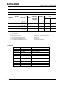
READING FEATURES
Frame Rate up to 30 frames / sec
Pitch 10° - 35°
Readable Codes
per Frame
up to100
Tilt 0° - 360°
Reading Distance
(3)
mm (in)
MODELS
Focus
Distance
mm (in)
Field of View
(1)
mm (in)
ppi
(2)
Typ. Linear
and Stacked
Code
Resolution
mm (mils)
Typ. 2D Code
Resolution
mm (mils)
min. max.
1021 HD 115 (4.52)
25 × 19
(0.98 × 0.75)
653 0.10 (4) 0.19 (7.5) 105 (4.13) 125 (4.92)
1031 SD 155 (6.10)
34 × 26
(1.34 × 1.02)
478 0.15 (6) 0.25 (10) 135 (5.31) 180 (7.08)
1041 LD 110 (4.33)
54 x 40
(2.13 × 1.57)
300 0.20 (8) 0.38 (15) 90 (3.45) 140 (5.51)
1051 MR 210 (8.26)
95 × 70
(3.74 × 2.75)
170 0.30 (12) 0.60 (24) 150 (5.90) 250 (9.84)
(1)
@ focus distance
(2)
Pixels per inch @ focus distance
(3)
Measurement conditions:
• Test chart: provided with the reader
• Still code at the center of the FOV
• Code symbology: Data Matrix ECC 200
• Code resolution: Typ. 2D Code Resolution
• Tilt angle: 45°
• Pitch angle: 15°
• Decode mode: Predictable
Accessories:
Order no. Accessory Description
93A051190 CAB-6001 cable to C-BOX100 1 m
93A051200 CAB-6002 cable to C-BOX100 2 m
93A051210 CAB-6005 cable to C-BOX100 5 m
93A051271 CAB-6010 cable to C-BOX100 10 m
93ACC1510 C-BOX 100 passive connection box
93A301000 C-BOX 300 Connection box PROFIBUS
93A301030 C-BOX 310 Connection box PROFIBUS with display
93A301010 C-BOX 400 Connection box DeviceNet
93A301040 C-BOX 410 Connection box DeviceNet with display
93ACC1718 PG6002 AC/DC power supply unit (US)
93ACC1719 PG6001 AC/DC power supply unit (UK)
93ACC1720 PG6000 AC/DC power supply unit (EU)
93A201090 GFC-MATRIX 90° deflection mirror

MATRIX-1000™ QUICK GUIDE
5
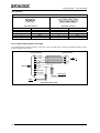
Electrical Connections:
The Matrix-1000™ reader provides a 25-pin male D-sub connector for connection to power supply, Host interface
(Main and Auxiliary), and input/output signals.
13
2514
1
25-pin male D-Sub Connector
25-pin male D-sub connector pinout
Pin Name Function
1 SHIELD Cable shield internally connected by capacitor to the chassis
2 RTX485+ RX or TX data of RS485 Half Duplex Main Interface - positive pin
4 RTX485- RX or TX data of RS485 Half Duplex Main Interface - negative pin
7 SGND Reference GND of RS485 Half Duplex Main Interface
3,5 NC
20 RXAUX Received data of RS232 Auxiliary Interface (referred to GND)
21 TXAUX Transmitted data of RS232 Auxiliary Interface (referred to GND)
8, 22 NC Not connected
11, 12 NC Not connected
16 OUT 3 + Configurable digital output 3 - positive pin
17 OUT 3 - Configurable digital output 3 - negative pin
18 EXT_TRIG A External trigger (polarity insensitive)
19 EXT_TRIG B External trigger (polarity insensitive)
6, 10 NC Not connected
14, 15, 24 NC Not connected
9,13 VS Supply voltage - positive pin
23, 25 GND Supply voltage - negative pin
A separate 9-pin female D-sub connector provides access to the auxiliary port.
5
1
9
6
9-pin female D-Sub Connector
9-pin female D-sub connector pinout
Pin Name Function
2 TXAUX
Transmitted data of RS232 Auxiliary Interface
3 RXAUX
Received data of RS232 Auxiliary Interface
5 GND
Reference GND of RS232 Auxiliary Interface
1,4,6,7,8,9 N.C.
Not connected
CAUTION
Do not connect GND and SGND to different (external) ground references. GND and SGND
are internally connected through filtering circuitry which can be permanently damaged if
subjected to voltage drops over 0.8 Vdc.

MATRIX-1000™ QUICK GUIDE
6
User Interface:
RS232 PC-side connections
1
5
9 6
9-pin male connector
13
25 14
1
25-pin male connector
Pin Name Pin Name
2 RX 3 RX
3 TX 2 TX
5 GND 7 GND
7 RTS 4 RTS
8 CTS 5 CTS
How To Build A Simple Interface Test Cable:
The following wiring diagram shows a simple test cable including power, external (push-button) trigger and PC
RS232 COM port connections.
25-pin D-sub female
23
20
GND
RXAUX
TXAUX
21
MATRIX
25
13
GND
VS
9-pin D-sub female
GND
TX
RX
PC
2
3
5
18
9
EXT TRIG+
VS
Power Supply
VS (10 – 30 VDC)
Power GND
Trigger
EXT TRIG-
19
Test Cable for Matrix-1000™

MATRIX-1000™ QUICK GUIDE
7
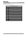
C-BOX 100 pinout for Matrix-1000™:
The table below gives the pinout of the C-BOX 100 terminal block connectors. Use this pinout when the Matrix-
1000™ reader is connected by means of the C-BOX 100:
C-BOX 100 Terminal Block Connectors
Power
1, 3, 5 VS
2, 4, 6 GND
7, 8 EARTH GROUND
20, 40 Reserved
Inputs
27 EXT TRIG A (polarity insensitive)
28 EXT TRIG B (polarity insensitive)
29, 30 NC
31, 33 NC
32, 34 NC
36 NC
Outputs
21, 22 NC
23, 24 NC
25 OUT 3+
26 OUT 3-
Auxiliary Interface
35 TX AUX
37 RX AUX
38, 39 GND
Main Interface
RS485 Half-Duplex
11, 15 RTX485+
12, 16 RTX485-
17 NC
18 NC
10, 14, 19 SGND
9, 13 RS485 Cable Shield

MATRIX-1000™ QUICK GUIDE
8
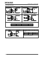
Input / Output Connections:
Input
USER INTERFACE
OUT
MATRIX
V
CC
A
Vext
B
GND
V
+
~
~
+
-
I
in
30 Vdc Max.
Input PNP command using external power
USER INTERFACE
MATRIX
V
CC
A
B
V
+
~
~
+
-
9
25
OUT
GND
GND
V
S
Input PNP command using Matrix-1000™ power
USER INTERFACE
VS
MATRIX
A
Vext
B
V
+
V
CC
~
~
+
-
GND
OUT
30 Vdc Max.
Input NPN command using external power
USER INTERFACE
VS
MATRIX
A
B
GND
V
+
V
CC
~
~
+
-
GND
9
OUT
25
Input NPN command using Matrix-1000™ power
The electrical features of the input are:
INPUT | V
AB
| Min. | V
AB
| Max. I
IN
Max
.
Open 0 V 2 V 0 mA
Closed 4.5 V 30 V 10 mA
Output
MATRIX
USER INTERFACE
Vext
30 Vdc max
+
-
I
Load
V
Out
Open collector output connection
The electrical features of the output are the
following:
OUTPUT I
Load
V
Out
Open 0 mA 30 Vdc Max
Closed 10 mA 1.8 Vdc Max
P
D
= V
out
× I
load
= 170 mW Max.

MATRIX-1000™ QUICK GUIDE
9
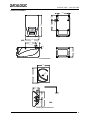
Mechanical Installation:
mm
[inch]
M4 x 5 n°4
18.1
[0.71]
4
[0.16]
73
[2.87]
57
[2.24]
= =
28.1
[1.11]
57
[2.24]
121
[4.76]
57
[2.24]
M4 x 5 n°4
57
[2.24]
Overall Dimensions
73
[2.87]
Ø
4
.
2
[
Ø
0
.
1
7
]
15
[0.59]
37
[1.46]
4.2
[0.17]
95
[3.74]
47.5
[1.87]
Ø
8
.
2
[
Ø
0
.
3
2
]
47.5
[1.87]
95
[3.74]
2
[0.08]
mm
[inch]
Mounting Bracket Dimensions

MATRIX-1000™ QUICK GUIDE
10
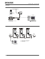
Connectivity:
Point-to-Point
Multiplexer
MX4000
C-BOX 100
C-BOX 100
C-BOX 100
Power
Host
e
e
e
d d
d
c
c Multidrop Network - Main Interface
d Auxiliary Interface (Local Echo)
e External Trigger
0
31
1
Matrix-1000™
c Auxiliary Interface (Local Echo)
d External Trigger
c
d
C-BOX 100
Matrix-1000™
Local Host
P.S.
PG6000
CAB-600X

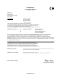
DATALOGIC S.p.A.,
Via Candini, 2
40012 - Lippo di Calderara
Bologna - Italy
dichiara che
declares that the
déclare que le
bescheinigt, daß das Gerät
declare que el
MATRIX-1XXX e tutti i suoi modelli
and all its models
et tous ses modèles
und seine modelle
y todos sus modelos
sono conformi alle Direttive del Consiglio Europeo sottoelencate:
are in conformity with the requirements of the European Council Directives listed below:
sont conformes aux spécifications des Directives de l'Union Européenne ci-dessous:
der nachstehend angeführten Direktiven des Europäischen Rats:
cumple con los requisitos de las Directivas del Consejo Europeo, según la lista siguiente:
89/336/EEC EMC Directive e 92/31/EEC, 93/68/EEC emendamenti successivi
and further amendments
et ses successifs amendements
und späteren Abänderungen
y succesivas enmiendas
Basate sulle legislazioni degli Stati membri in relazione alla compatibilità elettromagnetica ed alla sicurezza dei prodotti.
On the approximation of the laws of Member States relating to electromagnetic compatibility and product safety.
Basée sur la législation des Etates membres relative à la compatibilité électromagnétique et à la sécurité des produits.
Über die Annäherung der Gesetze der Mitgliedsstaaten in bezug auf elektromagnetische Verträglichkeit und Produktsicherheit
entsprechen.
Basado en la aproximación de las leyes de los Países Miembros respecto a la compatibilidad electromagnética y las Medidas
de seguridad relativas al producto.
Questa dichiarazione è basata sulla conformità dei prodotti alle norme seguenti:
This declaration is based upon compliance of the products to the following standards:
Cette déclaration repose sur la conformité des produits aux normes suivantes:
Diese Erklärung basiert darauf, daß das Produkt den folgenden Normen entspricht:
Esta declaración se basa en el cumplimiento de los productos con la siguientes normas:
EN 55022, August 1994: LIMITS AND METHODS OF MEASUREMENTS OF RADIO DISTURBANCE CHARACTERISTICS OF
INFORMATION TECHNOLOGY EQUIPMENT
(ITE)
EN 61000-6-2, October 2001: ELECTROMAGNETIC COMPATIBILITY (EMC).
PART 6-2: GENERIC STANDARDS – IMMUNITY FOR INDUSTRIAL ENVIRONMENTS
Lippo di Calderara, 14/09/04
Ruggero Cacioppo
Quality Assurance Supervisor
821000932 (Rev. B)
-
 1
1
-
 2
2
-
 3
3
-
 4
4
-
 5
5
-
 6
6
-
 7
7
-
 8
8
-
 9
9
-
 10
10
-
 11
11


Datalogic Matrix-1031 SD Quick Reference Manual
- Tipo
- Quick Reference Manual
- Questo manuale è adatto anche per
in altre lingue
- English: Datalogic Matrix-1031 SD
Documenti correlati
-
Datalogic Compact 2D Reader Matrix-2000 Quick Reference Manual
-
-
-
-
Datalogic DS2400N Guida di riferimento
-
-
-
-
Datalogic DS6300 Guida di riferimento