Datalogic DS6500 Series Guida di riferimento
- Tipo
- Guida di riferimento

DS6500
Reference Manual


DS6500
REFERENCE MANUAL

DATALOGIC S.p.A.
Via Candini 2
40012 - Lippo di Calderara di Reno
Bologna - Italy
DS6500 Reference Manual
Ed.: 11/2003
ALL RIGHTS RESERVED
Datalogic reserves the right to make modifications or improvements without prior notification.
Datalogic shall not be liable for technical or editorial errors or omissions contained herein, nor for
incidental or consequential damages resulting from the use of this material.
Product names mentioned herein are for identification purposes only and may be trademarks and or
registered trademarks of their respective companies.
© Datalogic S.p.A. 2003
28/11/03

iii
CONTENTS
REFERENCES ...........................................................................................................v
Reference Documentation ..........................................................................................v
Service, Support and Warranty ...................................................................................v
SAFETY REGULATIONS..........................................................................................vi
Electrical Safety ......................................................................................................... vi
Laser Safety............................................................................................................... vi
Power Supply............................................................................................................ vii
GENERAL VIEW .....................................................................................................viii
GUIDE TO INSTALLATION.......................................................................................xi
Point-to-Point Installation ........................................................................................... xi
Master/Slave Lonworks Installation........................................................................... xii
1 INTRODUCTION ........................................................................................................1
1.1 Product Description.....................................................................................................1
1.2 Available Models.........................................................................................................2
1.3 Indicators ....................................................................................................................3
1.4 Oscillating Mirror Models.............................................................................................3
1.5 Accessories ................................................................................................................6
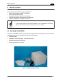
2 INSTALLATION..........................................................................................................7
2.1 Package Contents.......................................................................................................7
2.2 Mechanical Mounting ..................................................................................................8
2.2.1 Mounting the Scanner.................................................................................................8
2.2.2 Mounting the Scanner with Accessories....................................................................11
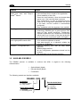
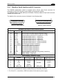
2.3 Electrical Connections...............................................................................................13
2.3.1 Main/Aux. Serial Interface and I/O Connector ...........................................................15
2.3.2 Lonworks Connectors ...............................................................................................24
2.3.3 Ethernet Connector...................................................................................................27
2.3.4 DeviceNet Connector................................................................................................29
2.3.5 Profibus Connector ...................................................................................................30
2.3.6 Power Supply............................................................................................................30
2.4 User Interface ...........................................................................................................31
2.5 Positioning the Scanner ............................................................................................32
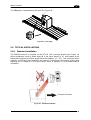
2.6 Typical Installations...................................................................................................33
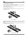
2.6.1 Standard Installation .................................................................................................33
2.6.2 “45° Skew” Installation ..............................................................................................34
2.7 Typical Layouts.........................................................................................................34
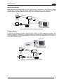
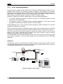
2.7.1 Point-to-Point ............................................................................................................34
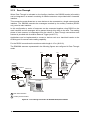
2.7.2 Pass Through ...........................................................................................................36
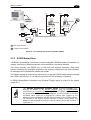
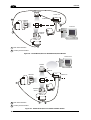
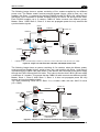
2.7.3 RS232 Master/Slave .................................................................................................37
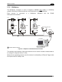
2.7.4 Multiplexer ................................................................................................................39
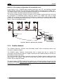
2.7.5 Local Lonworks Network ...........................................................................................40
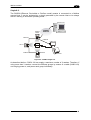
2.7.6 Fieldbus Network ......................................................................................................42
2.8 Keypad and Display ..................................................................................................44
2.8.1 Internal Net ...............................................................................................................44
2.8.2 Test Mode.................................................................................................................44

iv
3
SOFTWARE CONFIGURATION...............................................................................45
3.1 Genius™ Installation.................................................................................................45
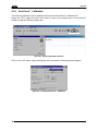
3.2 Guide to Rapid Configuration....................................................................................45
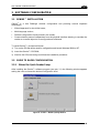
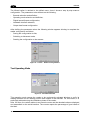
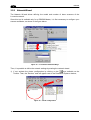
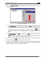
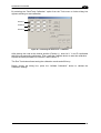
3.2.1 Wizard for Quick Reader Setup.................................................................................45
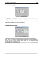
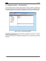
3.2.2 Network Wizard.........................................................................................................48
3.3 Advanced Genius™ Configuration ............................................................................50
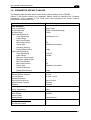
3.4 Parameter Default Values .........................................................................................51
4 READING FEATURES.............................................................................................54
4.1 Advanced Code Reconstruction (ACR™ 3)...............................................................54
4.1.1 Tilt Angle for Advanced Code Reconstruction ...........................................................54
4.2 Astra™......................................................................................................................55
4.3 PackTrack™ .............................................................................................................56
4.3.1 PackTrack™ Calibration ...........................................................................................58
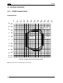
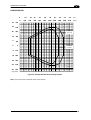
4.4 Reading Diagrams ....................................................................................................60
4.4.1 DS6500 Standard Model...........................................................................................60
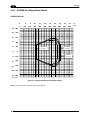
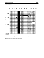
4.4.2 DS6500 Oscillating Mirror Model...............................................................................62
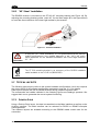
5 MAINTENANCE .......................................................................................................64
5.1 Cleaning....................................................................................................................64
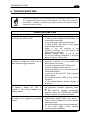
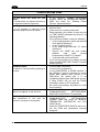
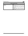
6 TROUBLESHOOTING..............................................................................................65
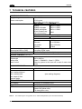
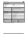
7 TECHNICAL FEATURES.........................................................................................68
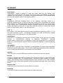
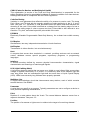
GLOSSARY..............................................................................................................70
INDEX.......................................................................................................................73

v
REFERENCES
REFERENCE DOCUMENTATION
The documentation related to the DS6500 management is listed below:
• C-BOX100 Installation Manual
• INT-60 20 mA Current Loop Interface Board
• PWR-120 power supply unit
• GFC-60 90° deflecting mirror
• GFC-600 90° deg. mirror close distance
• Document about the Ethernet connectivity
• Document about the Profibus connectivity
• Help On-Line in PDF format
SERVICE, SUPPORT AND WARRANTY
Services and Support
Datalogic provides several services as well as technical support through its website. Log on
to www.datalogic.com/services/support and click on the links
indicated for further information
including:
- Services
– Warranty Extensions and Maintenance Agreements
- Support
– Software Driver Downloads
- Contact Us
– Listing of Datalogic Subsidiaries and Quality Partners
- Authorised Repair Centres

vi
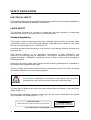
SAFETY REGULATIONS
ELECTRICAL SAFETY
This product conforms to the applicable requirements contained in the European Standard for
electrical safety EN-60950 at the date of manufacture.
LASER SAFETY
The following information is provided to comply with the rules imposed by international
authorities and refers to the correct use of the DS6500 reader.
Standard Regulations
This scanner utilizes a low-power laser diode. Although staring directly at the laser beam
momentarily causes no known biological damage, avoid staring at the beam as one would
with any very strong light source, such as the sun.
Avoid that the laser beam hits the eye of an observer, even through reflective surfaces such
as mirrors, etc.
This product conforms to the applicable requirements of both EN60825-1 and
CDRH 21 CFR1040 at the date of manufacture. The reader is classified as a Class 2 laser
product according to EN60825-1 regulations and as a Class II laser product according to
CDRH regulations.
Disconnect the power supply when opening the device during maintenance or installation to
avoid exposure to hazardous laser light.
There is a safety device which allows the laser to be switched on only if the motor is rotating
above the threshold for its correct scanning speed.
WARNING
Use of controls or adjustments or performance of procedures other than those
specified herein may result in exposure to hazardous visible laser light.
The laser light is visible to the human eye and is emitted from the window on the head of the
reader (Figure 1, 7).
Warning labels indicating exposure to laser light and the device classification are applied
onto the head of the reader (Figure 1, 1, 3):
AVOID EXPOSURE
LASER RADIATION IS EMITTED FROM THIS APERTURE
AVOID EXPOSURE – LASER LIGHT
IS EMITTED FROM THIS APERTURE
Laser Safety Label for Oscillating Mirror and Standard Models

vii
CAUTION-CLASS 3B
LASER LIGHT
WHEN OPEN
AVOID EXPOSURE
TO BEAM
LASER LIGHT – DO NOT STARE INTO BEAM
CLASS 2 LASER PRODUCT
MAX. OUTPUT RADIATION 1 mW
EMITTED WAVE LENGTH 630 ~ 680 nm
EN60825-1:2001
Warning and Device Class Label
The identification label is applied onto the bottom part of the scanner (Figure 1, 2):
N2468
DATALOGIC S.p.A. Via Candini, 2
40012 LIPPO DI CALDERARA DI RENO (BO) ITALY
MANUFACTURED VOLT Amp.
JANUARY 2002 15-30 DC 1.5-0.7
MODEL No.
SERIAL No.
This product conforms to the applicable requirements
of 21CFR 1040 at the date of manufacture.
Device Identification Label
The laser diode used in this device is classified as a Class 3B laser product according to
EN60825-1 regulations and as a Class IIIb laser product according to CDRH regulations. As it
is not possible to apply a classification label on the laser diode used in this device, the
following label is reproduced here:
LASER LIGHT
AVOID EXPOSURE TO BEAM
CLASS 3B LASER PRODUCT
MAXIMUM OUTPUT RADIATION 35 mW
EMITTED WAVE LENGTH 630~680 nm
TO EN60825-1 (2001)
Laser Diode Class Label
Any violation of the optic parts in particular can cause radiation up to the maximum level of
the laser diode (35 mW at 630~680 nm).
POWER SUPPLY
- This product is intended to be installed by Qualified Personnel only.
- All DS6500 Models:
This device is intended to be supplied by a UL Listed Power Unit marked “Class 2” or LPS
power source which supplies power directly to the scanner via the 25/26-pin connector.

viii
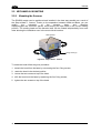
GENERAL VIEW
DS6500
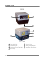
Figure 1 - DS6500
Laser Safety Label
Warning and Device Class Label
Identification Label
Connector Panel
Display and Keypad Panel
Laser Beam Output Window
1
3 7
6
5
2
Service Cap
4
6
4
3
1
2
7
5

ix
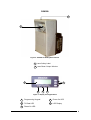
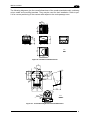
DS6500
Figure 2 - DS6500 Oscillating Mirror Version
Laser Safety Label
1
Laser Beam Output Window
2
Figure 3 - Display and Keypad Panel
Programming Keypad
Phase On LED
TX Data LED
Power On LED
LCD Display
1
2
3
5
4
4
1
2
3
5
1
2

x
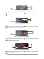
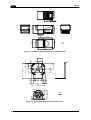
Figure 4 - Connector Panel for Master/Slave Models
Main/Aux. Interface 25 D-Sub male connector
Lonworks 9-pin male connector
Lonworks 9-pin female connector
1
2
3
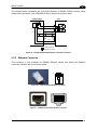
Figure 5 – Connector Panel for Ethernet Models
Main/Aux. Interface 26 D-Sub male connector
RJ45 Modular Connector for Ethernet Interace
Lonworks 9-pin female connector
1
2
3
Figure 6 – Connector Panel for DeviceNet Models
Main/Aux. Interface 26 D-Sub male connector
DeviceNet 5-pin Male Connector
Lonworks 9-pin female connector
1
2
3
Figure 7 – Connector Panel for Profibus Models
Main/Aux. Interface 26 D-Sub male connector
Profibus 9-pin Male Connector
Lonworks 9-pin female connector
1
2
3
3
2
1
3
2
1
1
3
2
1
3
2

xi
GUIDE TO INSTALLATION
POINT-TO-POINT INSTALLATION
The following can be used as a checklist to verify all the steps necessary to complete
installation of the DS6500 scanner.
1) Read all information in the section “Safety Precautions” at the beginning of this manual.
2) Correctly mount the scanner using the bracket provided according to the information in
par. 2.2.2.
3) Position the reader at the correct reading distance according to your model as shown in
par. 2.5.
4) Make electrical connections to your DS6500 scanner by:
a) Connecting the DS6500 scanner to the C-BOX 100 by means of one of the cables
provided as accessory (see par. 1.5).
b) Providing correct and complete system cabling through the C-BOX 100 according to
the signals (trigger, inputs, outputs) necessary for the layout of your application.
• Layout: Point-to-Point, RS232 Master/Slave, Lonworks, Fieldbus. See sub-
paragraphs under 2.7 for reference.
• Cabling: Power, Main Serial Interface – RS232, RS485 Half Duplex, RS485 Full
Duplex, 20 mA Current Loop, Auxiliary Interface, Inputs, Outputs, etc -. For further
details, see all sub-paragraphs under par. 2.3.
5) Configure the DS6500 scanner by installing and running the Genius™ configuration
program from the CD-ROM provided. The main steps are:
• Select the codes to be read
• Set-up the communication parameters
• Define data formatting parameters
• Fine tune your DS6500 scanner using the Test Mode as described in Genius™.
6) Exit the configuration program and run your application.
The installation is now complete.

xii
MASTER/SLAVE LONWORKS INSTALLATION
The following can be used as a checklist to verify all the steps necessary to complete
installation of the DS6500 scanner in a Master/Slave Lonworks network.
1) Repeat the previous procedure from step 1 to step 3.
2) Make electrical connections to your DS6500 scanner by:
a) Connecting the DS6500 Master
scanner to the C-BOX 100 by means of one of the
cables provided as accessory (see par. 1.5).
b) Correctly inserting the BTK-6000 terminator in the DS6500 Master reader according
to the information given under “Local Lonworks Network” in par. 2.3.2.
c) Completing the system wiring adding as much slave scanners as required by your
system layout (refer to par. 2.7).
d) Correctly inserting the BTK-6000 terminator in the last DS6500 Slave reader of the
network according to the information given under “Local Lonworks Network” in par.
2.3.2.
3) Configure the DS6500 Slave scanners using one of the procedures given below:
a) Defining each DS6500 slave scanner address by using the scanner keypad according
to the information given in par. 2.8.
b) Installing and running the Genius™ configuration program from the CD-ROM
provided and defining each DS6500 slave scanner address as described in par. 3.2.2.
4) Configure the DS6500 Master scanner using one of the procedures given below:
a) Configure the DS6500 scanner as Master by using the scanner keypad according to
the information given in par. 2.8.
b) Configure the DS6500 scanner as Master by using the Genius™ program as
described in par. 3.2.2.
5) Connect the DS6500 Master scanner to configure the network layout by using the
Genius™ program.
6) Configure all the DS6500 slave scanners through the Genius™ program. The main steps
are:
• Select the codes to be read
• Set-up the communication parameters
• Define data formatting parameters
NOTE
All slave scanners may also be configured remotely via Genius™
through the Master scanner.
7) Fine tune your DS6500 scanner using the Test Mode as described in Genius™.
The installation is now complete.

INTRODUCTION
1
1
1 INTRODUCTION
1.1 PRODUCT DESCRIPTION
The DS6500 is a high performance laser scanner in a complete range of industrial bar code
readers offering an innovative and modular solution in terms of reading performance,
connectivity and maintenance, in addition to a completely new hardware and software
platform.
The DS6500 has been specifically designed for simple installation, easy use and flexibility.
An innovative mechanical design together with the Datalogic patent pending Step-a-Head
TM
feature make it possible to rotate the reader head and the decoder base independently from
each other. Step-a-Head
TM
enables the DS6500 to always be installed in the ideal position,
by modifying the orientation of the connector panel while leaving the laser window in the
desired position. The need for space is minimized and installation is easier.
The DS6500 is based on the ASTRA™ technology which allows to switch electronically the
two laser diodes depending on the distance from the barcode. The real time depth of field
(DOF) provided by the DS6500 covers a wide set of applications, from the stand alone one to
the multisided tunnels conveyors.
The DS6500 can read all most popular bar codes even in the most difficult conditions, thanks
to a new generation decoder with StrongARM CPU and code reconstruction technology
(ACR™ 3).
This reader is also offered in a model with an integrated SW programmable oscillating mirror.
Great attention has been given to built-in connectivity for all market standards. Lonworks,
Profibus, Devicenet and Ethernet bus have been integrated in dedicated versions of the
decoder base.
Some of the main features of DS6500 are listed below:
• scanning speed up to 1200 scans/sec;
• 2 serial communication interfaces
• reading all popular codes;
• supply voltage from 15 to 30 Vdc;
• electrical connection through connectors;
• high speed Lonworks connectivity for Master/Slave layout;
• built-in connectivity for Profibus, Devicenet and Ethernet;
• programmable in 5 different operating modes to suit the most various barcode reading
system requirements;
• light source: solid state laser diode; the light emitted has a wavelength between
630~680nm.
• IP64 protection class of the enclosure (not yet available for Ethernet models).
Manufacturing is the traditional industry for Auto-ID applications, with a market becoming
mature, standardized reading solutions and a tough competition. Manufacturing has been the
target industry since the very beginning of the new 6000 family with the DS6300. The
DS6500 makes possible to enlarge the market applications including Transportation &
Logistics industry, making wider the Business Opportunities scenario.

DS6500
2
1
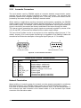
Feature Benefit
Modular solution with separated
head and base and Step-A-
Head
TM
feature
• Possibility to select the combination of head and
base that best fits the needs of the application;
• Great scalability of the offer;
• Down time cost reduction, since the decoder base
works even if the head has been removed;
• Easy maintenance. In case of replacement of the
head, all the configuration parameters are stored
in the base, and the scanner is automatically
configured;
• Easy installation with the minimum room needed.
Reading parcels on conveyors • As a result of the ASTRA™ double laser
technology, DS6500 gives a great real time DOF
even on high speed conveyors. Furthermore,
DS6500 implements the Packtrack
TM
functionality
which leads to an increase of the plant production
as a result of the augmented system throughput.
Master working as a multiplexer
on a high speed Lonworks bus
• Great competitiveness of the offer, since the cost
of an external multiplexer is saved;
• High data transfer on a industrial, reliable bus
running at 1,2 Mbit/sec.
GENIUS
TM
Configurator SW • Reduced learning time, with an easy wizard
approach;
• Multilanguage platform;
• All the configuration parameters stored into the
scanner;
• Not dependent on the Physical interface.
1.2 AVAILABLE MODELS
The DS6500 scanner is available in versions that differ in regard to the following
characteristics:
• Optical Model (Head)
• Decoder Model (Base)
• Focalization
The following models are therefore available:
Optical Model (Head)
0 = Standard
5 = Oscillating Mirror
Decoder Model (Base)
10 = Master/Slave
11 = Profibus
12 = Ethernet
15 = Devicenet
DS6500 - X0X - 0YY
Focalization
1 = Medium Version
2 = Long Version

INTRODUCTION
3
1
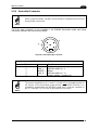
1.3 INDICATORS
The DS6500 decoder base provides an LCD display for system messages and configuration
menus. The three keys present on the side of the display allow configuration menu
navigation (Figure 3, 1).
The three LED indicators have the following functions:
POWER ON
(red) Indicates the reader is turned on (Figure 3, 4)
PHASE ON
(yellow) Indicates the presence sensor is turned on (Figure 3, 3).
TX DATA
(green) Indicates the main serial interface is operating correctly during
data transmission (Figure 3, 2).
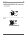
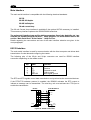
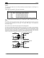
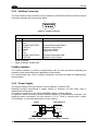
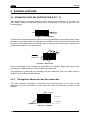
1.4 OSCILLATING MIRROR MODELS
Oscillating mirror models are used when coverage of a large reading area is required, mainly
in picket fence applications.
The DS6500 scanner mounts a dedicated optic head with integrated oscillating mirror driven
by a linear motor. The speed, the precision, the repeatability, and the reliability of this driving
technology assure high level performance.
The new oscillating mirror is completely software controlled and software programmable. The
Genius™ software tool allows adjusting the linear motor speed (oscillating frequency) and
the upper and lower limits of the oscillation by defining the top and bottom line limit angles.
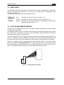
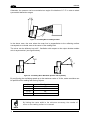
When the oscillating mirror is programmed to read barcode labels at very small angles,
position the reader to assure at least 10° for the Skew angle (see par. 2.4). This angle refers
to the most inclined or external laser line, so that all other laser lines assure more than 10°
Skew. This avoids the direct reflection of the laser light emitted by the reader.
1
0
°
Figure 8 – Oscillating Mirror Skew Angle

DS6500
4
1
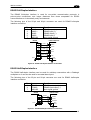
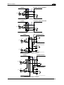
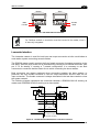
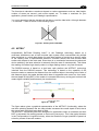
Otherwise, the scanner can be mounted at an angle of inclination of 17.5° in order to attain
symmetrical deflection ranges.
1
7
.
5
°
1
0
7
.
5
°
Figure 9 - Oscillating Mirror Reading Position
In the above case, the zone where the scan line is perpendicular to the reflecting surface
corresponds to a neutral zone at the center of the reading field.
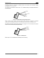
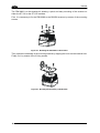
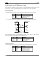
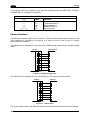
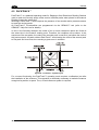
The mirror can be deflected up to 40°. Oscillation with respect to the output window median
axis is asymmetrical ( see figure below).
40°
3
7
.
5
°
0°
-
2
.
5
°
Figure 10 - Oscillating Mirror Maximum Aperture and Asymmetry
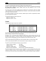
By configuring the oscillating speed up to the maximum value of 19 Hz, raster emulation can
be performed for reading fast moving objects.
Hz Max. Aperture
0-5 40°
6-10 30°
11-15 20°
16-19 10°
NOTE
By limiting the raster width to the minimum necessary, the number of
scans on the reading surface is increased.

INTRODUCTION
5
1
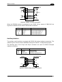
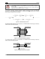
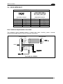
Oscillating angles are selected in software where the minimum and maximum angles
correspond to –2.5° and +37.5°.
The scanner can be tilted in order for the 17.5° software setting to correspond with the 0°
horizontal plane.
+17.5°
+37.5°
-2.5°
Figure 11 - Oscillating Mirror Extreme Angle Positions
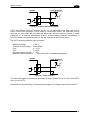
These models provide higher scanning speed (1200 scans/sec) compared to standard
models and the reading performance is not adversely effected by the oscillating mirror.
The following example represents the selection of an angle of +10° for the bottom line and an
angle of +20° for the top line (see figure below).
+17.5°
+37.5°
+27.5°
Figure 12 - Oscillating Mode
Refer to par. 2.2.1 for details about oscillating mirror mounting.

DS6500
6
1
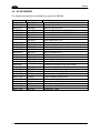
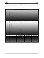
1.5 ACCESSORIES
The following accessories are available on request for DS6500:
Order no. Accessory Description
93A051190 CAB-6001 cable to C-BOX100 1 m
93A051200 CAB-6002 cable to C-BOX100 2 m
93A051210 CAB-6005 cable to C-BOX100 5 m
93A051221 CAB-6011 cable to C-BOX100 1 m (DS6500 Fieldbus version)
93A051222 CAB-6012 cable to C-BOX100 2 m (DS6500 Fieldbus version)
93A051223 CAB-6015 cable to C-BOX100 5 m (DS6500 Fieldbus version)
93A051220 CAB-6101 cable master/slave 1 m
93A051230
CAB-6102 cable master/slave 2 m
93A051240 CAB-6105 cable master/slave 5 m
93A051224 CAB-6112 cable master/slave no power 2 m
93A051225 CAB-6115 cable master/slave no power 5 m
93A051250 CAB-6205 cable to SC8000 5 m
93A051260 CAB-6210 cable to SC8000 10 m
93A15021 INT-60 20 m.A. C.L. interface board
93A201102 GFC-600 90° deg. mirror close distance
93ACC1510
C-BOX 100
passive connection box
93A301000
C-BOX 300
Profibus-DP connection box
93A301030
C-BOX 310
Profibus-DP connection box with display
93ACC1530 PWR-120 power unit 110/230 V AC 24 V
93ACC1710
BTK-6000 terminator kit (5 pcs)
93ACC1718
PG6002
single unit power supply (US)
93ACC1719
PG6001
single unit power supply (UK)
93ACC1720 PG6000 single unit power supply (EU)
93ACC1721 FBK-6000 fast bracket kit (2 pcs)
93A201100 GFC-60 90° mirror
890001020 US-60 mounting bracket kit (5 pcs) for multisided stations
93ACC1727 MEP-542 Photocell kit – PNP
93ACC1728 MEP-543 Photocell kit - NPN
La pagina si sta caricando...
La pagina si sta caricando...
La pagina si sta caricando...
La pagina si sta caricando...
La pagina si sta caricando...
La pagina si sta caricando...
La pagina si sta caricando...
La pagina si sta caricando...
La pagina si sta caricando...
La pagina si sta caricando...
La pagina si sta caricando...
La pagina si sta caricando...
La pagina si sta caricando...
La pagina si sta caricando...
La pagina si sta caricando...
La pagina si sta caricando...
La pagina si sta caricando...
La pagina si sta caricando...
La pagina si sta caricando...
La pagina si sta caricando...
La pagina si sta caricando...
La pagina si sta caricando...
La pagina si sta caricando...
La pagina si sta caricando...
La pagina si sta caricando...
La pagina si sta caricando...
La pagina si sta caricando...
La pagina si sta caricando...
La pagina si sta caricando...
La pagina si sta caricando...
La pagina si sta caricando...
La pagina si sta caricando...
La pagina si sta caricando...
La pagina si sta caricando...
La pagina si sta caricando...
La pagina si sta caricando...
La pagina si sta caricando...
La pagina si sta caricando...
La pagina si sta caricando...
La pagina si sta caricando...
La pagina si sta caricando...
La pagina si sta caricando...
La pagina si sta caricando...
La pagina si sta caricando...
La pagina si sta caricando...
La pagina si sta caricando...
La pagina si sta caricando...
La pagina si sta caricando...
La pagina si sta caricando...
La pagina si sta caricando...
La pagina si sta caricando...
La pagina si sta caricando...
La pagina si sta caricando...
La pagina si sta caricando...
La pagina si sta caricando...
La pagina si sta caricando...
La pagina si sta caricando...
La pagina si sta caricando...
La pagina si sta caricando...
La pagina si sta caricando...
La pagina si sta caricando...
La pagina si sta caricando...
La pagina si sta caricando...
La pagina si sta caricando...
La pagina si sta caricando...
La pagina si sta caricando...
La pagina si sta caricando...
La pagina si sta caricando...
La pagina si sta caricando...
-
 1
1
-
 2
2
-
 3
3
-
 4
4
-
 5
5
-
 6
6
-
 7
7
-
 8
8
-
 9
9
-
 10
10
-
 11
11
-
 12
12
-
 13
13
-
 14
14
-
 15
15
-
 16
16
-
 17
17
-
 18
18
-
 19
19
-
 20
20
-
 21
21
-
 22
22
-
 23
23
-
 24
24
-
 25
25
-
 26
26
-
 27
27
-
 28
28
-
 29
29
-
 30
30
-
 31
31
-
 32
32
-
 33
33
-
 34
34
-
 35
35
-
 36
36
-
 37
37
-
 38
38
-
 39
39
-
 40
40
-
 41
41
-
 42
42
-
 43
43
-
 44
44
-
 45
45
-
 46
46
-
 47
47
-
 48
48
-
 49
49
-
 50
50
-
 51
51
-
 52
52
-
 53
53
-
 54
54
-
 55
55
-
 56
56
-
 57
57
-
 58
58
-
 59
59
-
 60
60
-
 61
61
-
 62
62
-
 63
63
-
 64
64
-
 65
65
-
 66
66
-
 67
67
-
 68
68
-
 69
69
-
 70
70
-
 71
71
-
 72
72
-
 73
73
-
 74
74
-
 75
75
-
 76
76
-
 77
77
-
 78
78
-
 79
79
-
 80
80
-
 81
81
-
 82
82
-
 83
83
-
 84
84
-
 85
85
-
 86
86
-
 87
87
-
 88
88
-
 89
89


Datalogic DS6500 Series Guida di riferimento
- Tipo
- Guida di riferimento
in altre lingue
Documenti correlati
-
Datalogic DX6400 Guida di riferimento
-
-
-
Datalogic DS6300 Guida di riferimento
-
-
-
Datalogic DS2400N Guida di riferimento
-
-
-
Datalogic Switch SC6000 Manuale utente
Altri documenti
-
 Sopar 82010 Scheda dati
-
Genius 3-tlg Boden-Set Manuale utente
-
Rexel 11398201 Scheda dati
-
Axis A4020-E RFID Reader Guida d'installazione
-
Elvox 8017 Guida d'installazione
-
 Ditel DT-NP Technical Manual
-
 Axel GENIUS D Istruzioni per l'uso
-
Sony MDR-DS6500 Guida Rapida
-
Eurotherm 2404, 2408 Manuale del proprietario
-


