DS2400N
REFERENCE MANUAL

Datalogic Automation Srl
Via S. Vitalino, 13
40012 - Lippo di Calderara di Reno
Bologna - Italy
DS2400N Reference Manual
Ed.: 03/2007
ALL RIGHTS RESERVED
Datalogic S.p.A. reserves the right to make modifications and improvements without prior notification.
Datalogic shall not be liable for technical or editorial errors or omissions contained herein, nor for incidental or
consequential damages resulting from the use of this material.
Product names mentioned herein are for identification purposes only and may be trademarks and or
registered trademarks of their respective companies.
© Datalogic S.p.A. 1999 - 2007
19/03/07

CONTENTS
REFERENCES ............................................................................................ vi
Conventions ..................................................................................................vi
Reference Documentation ............................................................................vi
Services and Support....................................................................................vi
Patents..........................................................................................................vi
SAFETY REGULATIONS........................................................................... vii
Laser Safety.................................................................................................vii
Standard Regulations ..................................................................................vii
Power Supply..............................................................................................viii
CE Compliance ........................................................................................... viii
WEEE Compliance .....................................................................................viii
GENERAL VIEW ......................................................................................... ix
1 RAPID CONFIGURATION............................................................................ 1
Step 1 – Connect the System ....................................................................... 1
C-BOX 100/150 Pinout for DS2400N............................................................ 2
Step 2 – Mounting and Positioning the System............................................. 3
Step 3 – X-PRESS™ configuration............................................................... 5
Auto Learn .................................................................................................... 6
Auto Setup (Optional) ................................................................................... 7
Step 4 – Installing Genius™ Configuration Program..................................... 8
Wizard for Quick Reader Setup .................................................................... 8
step 5 – Test Mode ..................................................................................... 13
Advanced Scanner Configuration ............................................................... 14
Host Mode Programming ............................................................................ 14
Advanced Genius™ Configuration.............................................................. 14
Alternative Layouts ..................................................................................... 15
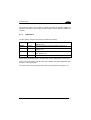
2 INTRODUCTION ........................................................................................ 16
2.1 Product Description..................................................................................... 16
2.1.1 Indicators .................................................................................................... 17
2.2 ID-NET™ .................................................................................................... 18
2.2.1 How To Setup/Configure the Scanner Network .......................................... 19
2.3 X-PRESS™ Human Machine Interface....................................................... 20
2.3.1 Diagnostic Indication................................................................................... 20
2.3.2 X-PRESS™ Functions ................................................................................ 21
Test Mode (F1) Function............................................................................. 21
AutoLearn (F2) Function ............................................................................. 22
AutoSetup (F3) Function............................................................................. 22
2.4 Model Description ....................................................................................... 23
iii

2.5 Accessories................................................................................................. 24
3 INSTALLATION.......................................................................................... 25
3.1 Package Contents....................................................................................... 25
3.2 Mechanical Installation................................................................................ 26
3.2.1 Mounting DS2400N..................................................................................... 27
3.2.2 Mounting Scanner Accessories................................................................... 28
3.3 Electrical Connections ................................................................................ 30
3.3.1 Power Supply.............................................................................................. 32
3.3.2 Main Serial Interface ................................................................................... 32
RS232 Interface .......................................................................................... 33
RS485 Full-Duplex Interface ....................................................................... 35
RS485 Half-Duplex Interface ...................................................................... 36
20 mA Current Loop Interface (C-Box 100 w/INT-30 Accessory Only) ....... 37
3.3.3 ID-NET™ .................................................................................................... 38
ID-NET™ Network Termination .................................................................. 42
3.3.4 Auxiliary RS232 Interface ........................................................................... 42
3.3.5 Inputs .......................................................................................................... 43
Code Verifier............................................................................................... 45
3.3.6 Outputs ....................................................................................................... 45
3.4 User Interface ............................................................................................. 46
3.5 Positioning .................................................................................................. 47
3.6 Typical Layouts........................................................................................... 49
3.6.1 Point-to-Point .............................................................................................. 49
3.6.2 Pass Through.............................................................................................. 50
3.6.3 RS232 Master/Slave ................................................................................... 51
3.6.4 ID-NET™ .................................................................................................... 52
3.6.5 Multiplexer Layout....................................................................................... 54
4 READING FEATURES ............................................................................... 55
4.1 Advanced Code Builder (ACB).................................................................... 55
4.1.1 Important ACB Reading Conditions ............................................................ 56
4.1.2 Tilt Angle Improvement with ACB ............................................................... 57
4.2 Linear Code Reading .................................................................................. 57
4.2.1 Step-Ladder Mode ...................................................................................... 58
4.2.2 Picket-Fence Mode ..................................................................................... 59
4.3 Performance ............................................................................................... 60
4.3.1 Raster ......................................................................................................... 60
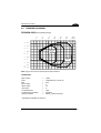
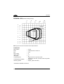
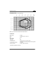
4.4 Reading Diagrams ...................................................................................... 61
5 MAINTENANCE ......................................................................................... 64
5.1 Cleaning...................................................................................................... 64
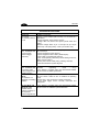
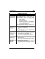
6 TROUBLESHOOTING ............................................................................... 65
6.1 General Guidelines ..................................................................................... 65
7 TECHNICAL FEATURES........................................................................... 68
iv


REFERENCES
CONVENTIONS
This manual uses the following conventions:
“User” or “Operator” refers to anyone using a DS2400N.
“Device” refers to the DS2400N.
“You” refers to the System Administrator or Technical Support person using this
manual to install, mount, operate, maintain or troubleshoot a DS2400N.
REFERENCE DOCUMENTATION
The documentation related to the DS2400N is listed below:
• C-BOX 100 Installation Manual
• INT-30 20 mA Current Loop Interface Board for C-BOX 100
• C-BOX 300/310 Installation Manual
• C-BOX 400/410 Installation Manual
• Genius™ Help On Line
SERVICES AND SUPPORT
Datalogic provides several services as well as technical support through its website.
Log on to www.datalogic.com and click on the
links indicated for further information
including:
•
PRODUCTS
Search through the links to arrive at your product page where you can download
specific
Manuals and Software & Utilities
• SERVICES & SUPPORT
-
Datalogic Services - Warranty Extensions and Maintenance Agreements
-
Authorised Repair Centres
• CONTACT US
E-mail form and listing of Datalogic Subsidiaries
PATENTS
This product is covered by one or more of the following patents:
U.S. patent 5,992,740
European patent 789,315 B1
vi

SAFETY REGULATIONS
LASER SAFETY
The following information is provided to comply with the rules imposed by
international authorities and refers to the correct use of the DS2400N scanner.
Standard Regulations
This scanner utilizes a low-power laser diode. Although staring directly at the laser
beam momentarily causes no known biological damage, avoid staring at the beam as
one would with any very strong light source, such as the sun. Avoid that the laser
beam hits the eye of an observer, even through reflective surfaces such as mirrors,
etc.
This product conforms to the applicable requirements of both EN 60825-1 and CDRH
21 CFR 1040 at the date of manufacture. The scanner is classified as a Class 2 laser
product according to EN 60825-1 regulations and as a Class II laser product
according to CDRH regulations.
There is a safety device, which allows the laser to be switched on only if the motor is
rotating above the threshold for its correct scanning speed.
The motor and laser beam can be switched off through a software command (see
also the Genius™ Help On Line).
WARNING
Use of controls or adjustments or performance of procedures other
than those specified herein may result in exposure to hazardous
visible laser light.
The laser light is visible to the human eye and is emitted from the window on the front
of the scanner (Figure A, 9).
Warning labels indicating exposure to laser light and the device classification are
applied onto the body of the scanner (Figure A, 1).
vii

Disconnect the power supply when
opening the device during maintenance
or installation to avoid exposure to
hazardous laser light.
The laser diode used in this device is
classified as a class 3B laser product
according to EN 60825-1 regulations
and as a Class IIIb laser product
according to CDRH regulations.
Any violation of the optic parts in
particular can cause radiation up to the
maximum level of the laser diode (35
mW at 630 to 680 nm).
AVOID EXPOSURE LASER LIGHT
IS EMITTED FROM THIS APERTURE
CAUTION-CLASS 3B LASER LIGHT
WHEN OPEN AVOID EXPOSURE TO BEAM
This product conforms to the
applicable requirements
of 21CFR1040 at the
date of manufacture
LASER LIGHT
DO NOT STARE INTO BEAM
CLASS 2 LASER PRODUCT
MAX. OUTPUT RADIATION 1 mW
EMITTED WAVE LENGTH 630~680 nm
TO EN 60825-1:2001
Pat. US5992740, EP0789315B1
DATALOGIC AUTOMATION Srl
Via S. Vitalino, 13 – 40012 Calderara di Reno
MADE IN ITALY-
www.datalogic.com
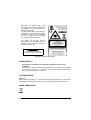
Warning and Device Class Labels
POWER SUPPLY
- This product is intended to be installed by Qualified Personnel only.
- All Models:
This accessory device is intended to be supplied by a UL Listed or CSA Certified
Power Unit with «Class 2» or LPS power source, which supplies power directly
to the scanner via the 25-pin connector.
CE COMPLIANCE
Warning:
This is a Class A product. In a domestic environment this product may cause radio
interference in which case the user may be required to take adequate measures.
WEEE COMPLIANCE
viii

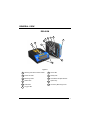
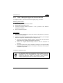
GENERAL VIEW
DS2400N
3
11
6
7
8
2
9
5
1
10
4
Figure A
1
2
3
4
10
9
8
6
Warning and Device Class Labels
Power ON LED
Mounting Holes
Status LED
Trigger LED
Ready LED
Laser Beam Output Window
Xpress key
7
Good LED
5
COM LED
A
ccessory Mounting Holes
11
ix

x

RAPID CONFIGURATION
1
1 RAPID CONFIGURATION
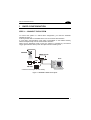
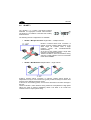
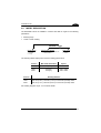
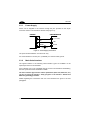
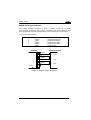
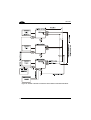
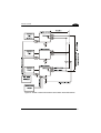
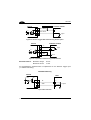
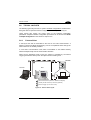
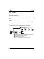
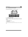
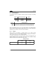
STEP 1 – CONNECT THE SYSTEM
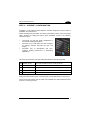
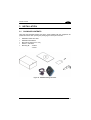
To connect the system in a Stand Alone configuration, you need the hardware
indicated in Figure 1.
In this layout the data is transmitted to the Host on the main serial interface.
In Local Echo communication mode, data is transmitted on the RS232 auxiliary
interface independently from the main interface selection.
When On-Line Operating mode is used, the scanner is activated by an External
Trigger (photoelectric sensor) when the object enters its reading zone.
DS2400N
CBOX-100/150
Host
P.S.*
PG 6000
* Presence Sensor (for On-Line mode)
Figure 1 – DS2400N in Stand Alone Layout
1

DS2400N
1
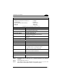
C-BOX 100/150 Pinout for DS2400N
The table below gives the pinout of the C-BOX 100/150 terminal block connectors.
Use this pinout when the DS2400N reader is connected in a network by means of the
C-BOX 100/150:
C-BOX 100/150 Terminal Block Connectors
Power Outputs
1, 3, 5 VS 21 OUT 1+
2, 4, 6 GND 22 OUT 1-
7, 8 EARTH GROUND 23 OUT 2+
20, 40 Reserved 24 OUT 2-
Inputs
25 NC
27
EXT TRIG A (polarity
insensitive)
26 NC
28
EXT TRIG B (polarity
insensitive)
Auxiliary Interface
29 NC 35 TX AUX
30 IN2- 37 RX AUX
31, 33 NC
ID-NET™
32, 34 NC 36 ID-NET-
39 GND 38 ID-NET+
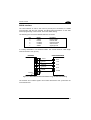
Main Interface
RS232
RS485 Full-
Duplex
RS485 Half-Duplex
20 mA C.L.
(with INT-30 only)
11, 15 TX 232 TX 485+ RTX 485+
12, 16 RTS 232 TX 485- RTX 485-
17 RX 232 RX 485+
18 CTS 232 RX 485-
10, 14,
19
SGND SGND SGND
9, 13
RS485 Cable
Shield
RS485 Cable Shield
see INT-30
instructions
CAUTION
Do not connect GND and SGND to different (external) ground
references. GND and SGND are internally connected through
filtering circuitry which can be permanently damaged if subjected to
voltage drops over 0.8 Vdc.
2

RAPID CONFIGURATION
1
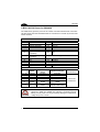
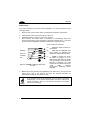
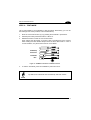
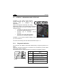
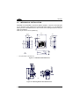
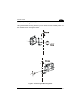
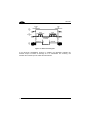
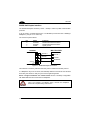
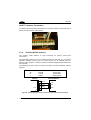
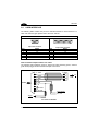
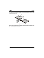
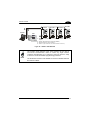
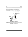
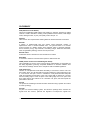
STEP 2 – MOUNTING AND POSITIONING THE SYSTEM
1. To mount the DS2100N, use the mounting bracket to obtain the most suitable
position for the reader as shown in the figures below.
Pitch
Skew
Tilt
Skew
Figure 2 - Positioning with Mounting Bracket
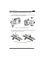
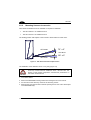
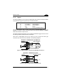
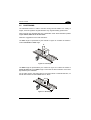
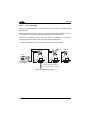
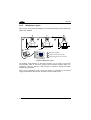
2. When mounting the DS2100N take into consideration these three ideal label position
angles: Pitch 0°, Skew 10° to 30° and Tilt 0°.
Minimize Assure at least 10°
P
S
Figure 3 – Pitch and Skew Angles
3

DS2400N
1
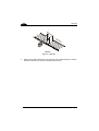
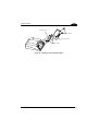
T
Minimize
Figure 4 – Tilt Angle
3. Refer to the Reading Diagrams in the Appendix of this Quick Reference Guide to
decide the distance your scanner should be positioned at.
4

RAPID CONFIGURATION
1
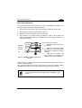
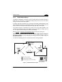
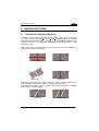
STEP 3 – X-PRESS™ CONFIGURATION
X-PRESS™ is the intuitive Human Machine Interface designed to improve ease of
installation and maintenance.
Status and diagnostic information are clearly presented by means of the five colored
LEDs, whereas the single push button gives immediate access to the following
relevant functions:
• Test Mode (F1) with bar graph visualization to
check static reading performance
• AutoLearn (F2) to self-detect and auto-configure
for reading unknown barcodes (by type and
length)
• AutoSetup (F3) to self-optimize and auto-
configure reading performance in demanding
applications
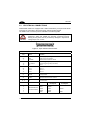
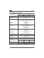
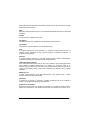
The colors and meaning of the five LEDs are illustrated in the following table:
F4 READY (green) This LED indicates the device is ready to operate.
F3 GOOD (green) This LED confirms successful reading.
F2 TRIGGER (yellow) This LED indicates the status of the reading phase.
F1 COM (yellow) This LED indicates active communication on main serial port.
F0 STATUS (red) This LED indicates a NO READ result.
During the reader startup (reset or restart phase), all the LEDs blink for one second.
On the back of the reader near the cable, the “POWER ON” LED indicates the laser
scanner is correctly powered.
5

DS2400N
1
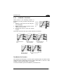
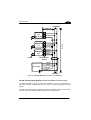
Auto Learn
If you are configuring your scanner using X-PRESS™, you must start with the Auto
Learn procedure.
1. Enter the Auto Learn function (F2) by pressing the X-PRESS™ push button.
2. Hold the push button pressed until the F2 LED is on.
3. Release the button to enter the Auto Learn function.
Once entered, the reader starts a procedure to automatically detect and
recognize barcodes (by type and length), which are presented to it (*). The laser
turns on and the TRIGGER LED blinks to indicate the ongoing process.
F4
F3
F2
F1
F0
READY
GOOD
TRIGGER
COM
STATUS
A
utoSetup
A
utoLearn
Test Mode
Exit
Figure 5 – X-PRESS™ Interface: Auto Learn
Function
The procedure is as follows:
A) place the desired barcode on
the scanline.
B) wait until the TRIGGER LED
stays steady on (indicating the
reader has detected the barcode).
C) repeat, if needed, the above
two steps to program up to 10
different barcodes (either by length
or by symbology). If more than one
barcode is detected, the Multi
Label mode is enabled (refer to the
“2000 Family Software
Configuration Parameter Guide”
Help file).
4. Exit the process by pressing the X-PRESS™ push button once. The scanner will
restart at the end of the process, and then the detected barcodes are
automatically configured in scanner memory.
NOTE
If the barcode cannot be read because of low contrast or excessive
ambient light, you can perform the AutoSetup function to optimize the
optical parameters. Then you can perform AutoLearn to recognize
the barcode symbology.
6

RAPID CONFIGURATION
1
Auto Setup (Optional)
At the end of the Auto Learn procedure, you have the possibility to follow the Auto
Setup procedure to set up the reading parameters.
1. Enter the Auto Setup function (F3) by pressing the X-PRESS™ push button.
2. Hold the push button pressed until the F3 LED is on.
3. Release the button to enter the Auto Setup function.
4. Once entered, if a barcode label is positioned in front of the scanline, the
scanner automatically performs the optimal setup of the reading parameters for
that specific barcode.
F4
F3
F2
F1
F0
READY
GOOD
T
RIGGER
COM
STATUS
A
utoSetup
A
utoLearn
Test Mode
Exit
Figure 6 – X-PRESS™ Interface: Auto Learn
Function
The procedure is as follows:
A) place the desired barcode on
the scanline.
B) enter the AutoSetup function
(the laser turns on and the GOOD
LED blinks to indicate the ongoing
process)
C) wait until the GOOD LED
stays steady on (indicating the
reader has detected the barcode)
This procedure ends either when the barcode is successfully decoded or after a timeout
of about 7 (seven) seconds.
The scanner will restart at the end of the process, and then the optimized reading
parameters for that barcode are automatically configured in scanner memory.
NOTE
If your application has been configured using X-PRESS™, go to
STEP 5.
7

DS2400N
1
STEP 4 – INSTALLING GENIUS™ CONFIGURATION PROGRAM
Genius
™
is a Datalogic scanner configuration tool providing several important
advantages:
• Wizard approach for low skilled users;
• Multi-language version;
• Defined configuration directly stored in the reader;
• Communication protocol independent from the physical interface allowing to
consider the reader as a remote object to be configured and monitored.
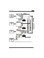
To install Genius™, turn on the PC that will be used for the configuration, running
Windows 98, 2000/NT or XP, then insert the Genius™ CD-ROM, wait for the CD to
autorun and follow the installation procedure.
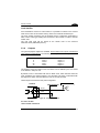
This configuration procedure assumes scanner connection to a C-BOX 100/150.
Genius™, running on a laptop computer, is connected to the scanner auxiliary port
through the C-BOX 100/150 9-pin connector.
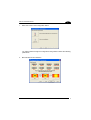
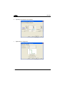
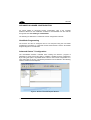
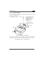
Wizard for Quick Reader Setup
After installing the Genius™ software program the following window appears asking
the user to choose the desired configuration level.
Figure 7 - Genius™ Wizard Opening Window
The Wizard option is advised to low skilled users, since it shows a step-by-step
scanner configuration.
8

RAPID CONFIGURATION
1
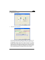
1. Select the Create a new configuration button.
You will be guided through the configuration being asked to define the following
parameters:
a. Barcode selection and definition
9

DS2400N
1
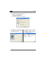
b. Operating mode selection and definition
c. Digital Outputs configuration
10
La pagina si sta caricando...
La pagina si sta caricando...
La pagina si sta caricando...
La pagina si sta caricando...
La pagina si sta caricando...
La pagina si sta caricando...
La pagina si sta caricando...
La pagina si sta caricando...
La pagina si sta caricando...
La pagina si sta caricando...
La pagina si sta caricando...
La pagina si sta caricando...
La pagina si sta caricando...
La pagina si sta caricando...
La pagina si sta caricando...
La pagina si sta caricando...
La pagina si sta caricando...
La pagina si sta caricando...
La pagina si sta caricando...
La pagina si sta caricando...
La pagina si sta caricando...
La pagina si sta caricando...
La pagina si sta caricando...
La pagina si sta caricando...
La pagina si sta caricando...
La pagina si sta caricando...
La pagina si sta caricando...
La pagina si sta caricando...
La pagina si sta caricando...
La pagina si sta caricando...
La pagina si sta caricando...
La pagina si sta caricando...
La pagina si sta caricando...
La pagina si sta caricando...
La pagina si sta caricando...
La pagina si sta caricando...
La pagina si sta caricando...
La pagina si sta caricando...
La pagina si sta caricando...
La pagina si sta caricando...
La pagina si sta caricando...
La pagina si sta caricando...
La pagina si sta caricando...
La pagina si sta caricando...
La pagina si sta caricando...
La pagina si sta caricando...
La pagina si sta caricando...
La pagina si sta caricando...
La pagina si sta caricando...
La pagina si sta caricando...
La pagina si sta caricando...
La pagina si sta caricando...
La pagina si sta caricando...
La pagina si sta caricando...
La pagina si sta caricando...
La pagina si sta caricando...
La pagina si sta caricando...
La pagina si sta caricando...
La pagina si sta caricando...
La pagina si sta caricando...
La pagina si sta caricando...
La pagina si sta caricando...
La pagina si sta caricando...
La pagina si sta caricando...
La pagina si sta caricando...
-
 1
1
-
 2
2
-
 3
3
-
 4
4
-
 5
5
-
 6
6
-
 7
7
-
 8
8
-
 9
9
-
 10
10
-
 11
11
-
 12
12
-
 13
13
-
 14
14
-
 15
15
-
 16
16
-
 17
17
-
 18
18
-
 19
19
-
 20
20
-
 21
21
-
 22
22
-
 23
23
-
 24
24
-
 25
25
-
 26
26
-
 27
27
-
 28
28
-
 29
29
-
 30
30
-
 31
31
-
 32
32
-
 33
33
-
 34
34
-
 35
35
-
 36
36
-
 37
37
-
 38
38
-
 39
39
-
 40
40
-
 41
41
-
 42
42
-
 43
43
-
 44
44
-
 45
45
-
 46
46
-
 47
47
-
 48
48
-
 49
49
-
 50
50
-
 51
51
-
 52
52
-
 53
53
-
 54
54
-
 55
55
-
 56
56
-
 57
57
-
 58
58
-
 59
59
-
 60
60
-
 61
61
-
 62
62
-
 63
63
-
 64
64
-
 65
65
-
 66
66
-
 67
67
-
 68
68
-
 69
69
-
 70
70
-
 71
71
-
 72
72
-
 73
73
-
 74
74
-
 75
75
-
 76
76
-
 77
77
-
 78
78
-
 79
79
-
 80
80
-
 81
81
-
 82
82
-
 83
83
-
 84
84
-
 85
85


in altre lingue
- English: Datalogic DS2400N Reference guide
Documenti correlati
-
Datalogic C-BOX 200 Guida d'installazione
-
-
-
-
-
-
-
Datalogic Switch SC6000 Manuale utente
-
-
Datalogic Falcon X4 Manuale utente