Zenith HealthView H20F50DT Manuale utente
- Tipo
- Manuale utente

© Copyright 2003, Zenith Electronics Corporation
Installation and Operating Guide | Warranty
Model Number | H20F50DT | HealthView
TM
TV
table of contents
page
5

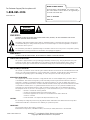
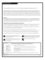
WARNING:
TO REDUCE THE RISK OF ELECTRIC SHOCK DO NOT REMOVE COVER (OR BACK). NO USER SERVICEABLE PARTS INSIDE.
REFER TO QUALIFIED SERVICE PERSONNEL.
The lightning flash with arrowhead symbol, within an equilateral triangle, is intended to alert the user to the presence
of uninsulated “dangerous voltage” within the product’s enclosure that may be of sufficient magnitude to constitute a
risk of electric shock to persons.
The exclamation point within an equilateral triangle is intended to alert the user to the presence of important operating
and maintenance (servicing) instructions in the literature accompanying the appliance.
WARNING:
TO PREVENT FIRE OR SHOCK HAZARDS, DO NOT EXPOSE THIS PRODUCT TO RAIN OR MOISTURE.
POWER CORD POLARIZATION:
This product is equipped with a 3-wire grounding-type alternating current line plug. This plug will fit into the power
outlet only one way. This is a safety feature. If you are unable to insert the plug fully into the outlet, contact your
electrician to replace your obsolete outlet. Do not defeat the safety purpose of the three-wire ground type plug.
NOTE TO CABLE/TV INSTALLER:
This reminder is provided to call the cable TV system installer’s attention to Article 820-40 of the National Electric Code
(U.S.A.). The code provides guidelines for proper grounding and, in particular, specifies that the cable ground shall be
connected to the grounding system of the building, as close to the point of the cable entry as practical.
REGULATORY INFORMATION:
This equipment has been tested and found to comply with the limits for a Class B digital device, pursuant to Part 15
of the FCC Rules. These limits are designed to provide reasonable protection against harmful interference when the
equipment is operated in a residential installation. This equipment generates, uses and can radiate radio frequency
energy and, if not installed and used in accordance with the instruction manual, may cause harmful interference to radio
communications. However, there is no guarantee that interference will not occur in a particular installation. If this
equipment does cause harmful interference to radio or television reception, which can be determined by turning
the equipment off and on, the user is encouraged to try to correct the interference by one or more of the following
measures:
• Reorient or relocate the receiving antenna.
• Increase the separation between the equipment and receiver.
• Connect the equipment into an outlet on a circuit different from that to which the
receiver is connected.
• Consult the dealer or an experienced radio/TV technician for help.
CAUTION:
Do not attempt to modify this product in any way without written authorization from Zenith Electronics Corporation.
Unauthorized modification could void the user’s authority to operate this product.
COMPLIANCE:
The responsible party for this product’s compliance is:
Zenith Electronics Corporation, 2000 Millbrook Drive, Lincolnshire, IL 60069, USA. Phone: 1-847-941-8000.
WARNING
RISK OF ELECTRIC SHOCK
DO NOT OPEN
3-WIRE COMM-WARN B-2/02
HealthView
TM
is a trademark of Zenith Electronics Corporation
© Copyright 2003 Zenith Electronics Corporation
RECORD THE MODEL NUMBER
The serial number of this HealthView
TM
TV is located on the
back of the cabinet. For future reference, we suggest that you
record the serial number here:
MODEL NO. H20F50DT
SERIAL NO.____________________________________
For Customer Support/Service please call:
1-888-865-3026
www.zenith.com

PAGE 3
206-3489-O
1. Read Instructions
All the safety and operating instructions should be read
before the product is operated.
2. Follow Instructions
All operating and use instructions should be followed.
3. Retain Instructions
The safety and operating instructions should be retained for
future reference.
4. Heed Warnings
All warnings on the product and in the operating instruc-
tions should be adhered to.
5. Cleaning
Unplug this product from the wall outlet before cleaning.
Do not use liquid cleaners or aerosol cleaners. Use a damp
cloth for cleaning.
6. Water and Moisture
Do not use this product near water for example, near a
bath tub, wash bowl, kitchen sink, or laundry tub, in a wet
basement, or near a swimming pool.
7. Accessories, Carts, and Stands
Do not place this product on a slippery or tilted surface, or
on an unstable cart, stand, tripod, bracket, or table. The
product may slide or fall, causing serious injury to a child
or adult, and serious damage to the product. Use only with
a cart, stand, tripod, bracket, or table recommended by the
manufacturer, or sold with the product. Any mounting of
the product should follow the manufacturer’s instructions,
and should use a mounting accessory recommended by the
manufacturer.
8. Transporting Product
A product and cart combination should be moved with care.
Quick stops, excessive force, and uneven surfaces may
cause the product and cart combination to overturn.
9. Attachments
Do not use attachments not recommended by the product
manufacturer as they may cause hazards.
10. Ventilation
Slots and openings in the cabinet are provided for ventila-
tion and to ensure reliable operation of the product and to
protect it from overheating, and these openings must not
be blocked or covered. The openings should never be
blocked by placing the product on a bed, sofa, rug, or
other similar surface. This product should not be placed in
a built-in installation such as a bookcase or rack unless
proper ventilation is provided or the manufacturer’s instruc-
tions have been adhered to.
11. Power Sources
This product should be operated only from the type of
power source indicated on the marking label. If you are not
sure of the type of power supply to your home, consult
your product dealer or local power company. For products
intended to operate from battery power, or other sources,
refer to the operating instructions.
12. Power Cord Polarization
This product is equipped with a three-wire grounding type
alternating-current power plug. This plug will fit into the
power outlet only one way. This is a safety feature. If you
are unable to insert the plug fully into the outlet, contact
your electrician to replace your obsolete outlet. Do not
defeat the safety purpose of the three-wire ground-type
plug.
13. Power Cord Protection
Power-supply cords should be routed so that they are not
likely to be walked on or pinched by items placed upon or
against them, paying particular attention to cords at plugs,
convenience receptacles, and the point where they exit
from the product.
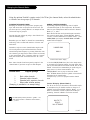
Important safeguards for you and your new product
This product has been manufactured and tested with safety in mind. However, improper use can result in potential electri-
cal shock or fire hazards. To avoid defeating the safeguards that have been built into the new product, please read and
observe the following safety points when installing and using the new product, and save them for future reference.
Observing the simple precautions discussed in this installation and operating guide can help get many years of enjoyment
and safe operation that are built into the new product.
This product complies with all applicable U.S. Federal safety requirements, and those of the Canadian Standards Association.
(Continued on next page)
PORTABLE CART WARNING
IMPORTANT SAFETY INSTRUCTIONS

(Continued from previous page)
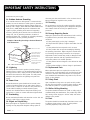
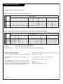
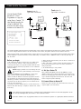
14. Outdoor Antenna Grounding
If an outside antenna or cable system is connected to the
product, be sure the antenna or cable system is grounded so
as to provide some protection against voltage surges and
built-up static charges. Article 810 of the National Electrical
Code (U.S.A.), ANSI/ NFPA 70 provides information with
regard to proper grounding of the mast and supporting
structure, grounding of the lead-in wire to an antenna dis-
charge unit, size of grounding conductors, location of
antenna-discharge unit, connection to grounding electrodes,
and requirements for the grounding electrode.
15. Lightning
For added protection for this product (receiver) during a
lightning storm, or when it is left unattended and unused
for long periods of time, unplug it from the wall outlet and
disconnect the antenna or cable system. This will prevent
damage to the product due to lightning and power-line
surges.
16. Power Lines
An outside antenna system should not be located in the
vicinity of overhead power lines or other electric light or
power circuits, or where it can fall into such power lines or
circuits. When installing an outside antenna system,
extreme care should be taken to keep from touching such
power lines or circuits as contact with them might be fatal.
17. Overloading
Do not overload wall outlets and extension cords as this can
result in a risk of fire or electric shock.
18. Object and Liquid Entry
Never push objects of any kind into this product through
openings as they may touch dangerous voltage points or
short-out parts that could result in a fire or electric shock.
Never spill liquid of any kind on the product.
19. Servicing
Do not attempt to service this product yourself as opening
or removing covers may expose you to dangerous voltage or
other hazards. Refer all servicing to qualified service
personnel.
20. Damage Requiring Service
Unplug this product from the wall outlet and refer servicing
to qualified service personnel under the following
conditions:
a. If the power-supply cord or plug is damaged.
b. If liquid has been spilled, or objects have fallen into the
product.
c. If the product has been exposed to rain or water.
d. If the product does not operate normally by following
the operating instructions. Adjust only those controls that
are covered by the operating instructions as an improper
adjustment of other controls may result in damage and will
often require extensive work by a qualified technician to
restore the product to its normal operation.
e. If the product has been dropped or the cabinet has been
damaged.
f. If the product exhibits a distinct change in performance.
21. Replacement Parts
When replacement parts are required, be sure the service
technician has used replacement parts specified by the man-
ufacturer or have the same characteristics as the original
part. Unauthorized substitutions may result in fire, electric
shock, or other hazards.
22. Safety Check
Upon completion of any service or repairs to this product,
ask the service technician to perform safety checks to deter-
mine that the product is in proper operating condition.
23. Wall or Ceiling Mounting
The product should be mounted to a wall or ceiling only as
recommended by the manufacturer. The product may slide or
fall, causing serious injury to a child or adult, and serious
damage to the product.
24. Heat
The product should be situated away from heat sources such
as radiators, heat registers, stoves, or other products
(including amplifiers) that produce heat.
PAGE 4
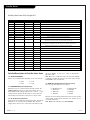
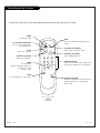
Antenna Lead in Wire
Antenna Discharge Unit
(NEC Section 810-20)
Grounding Conductor
(NEC Section 810-21)
Ground Clamps
Power Service Grounding
Electrode System (NEC
Art 250, Part H)
Ground Clamp
Electric Service
Equipment
Example of Grounding According to National Electrical
Code Instructions
NEC - National Electrical Code
206-3491-O
IMPORTANT SAFETY INSTRUCTIONS

PAGE 5
Table of Contents
Safety Warnings . . . . . . . . . . . . . . . . . . . . . . . . . . . 2
Important Safety Instructions . . . . . . . . . . . . . . . . 3 - 4
Table of Contents . . . . . . . . . . . . . . . . . . . . . . . . . . 5
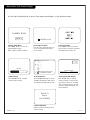
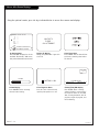
Step 1. Hook Up the HealthView TV
TV and other Equipment Hookups
Antenna . . . . . . . . . . . . . . . . . . . . . . . . . . . . . . . . 6
Cable Service . . . . . . . . . . . . . . . . . . . . . . . . . . . . . 7
Antenna with VCR . . . . . . . . . . . . . . . . . . . . . . . . . . 8
Cable service with VCR . . . . . . . . . . . . . . . . . . . . . . . 9
External Speaker Connection (8-ohm output) . . . . . . . . 9
Pillow Speaker . . . . . . . . . . . . . . . . . . . . . . . . . . . 10
Step 2. Channel Search and Reception Setup
Auto Program . . . . . . . . . . . . . . . . . . . . . . . . . . . . 11
(Select Antenna, or cable service then do channel search)
Front Panel Controls . . . . . . . . . . . . . . . . . . . . . . . . 12
Optional Installer’s Remote Key Functions . . . . . . . . . . 13
On-Screen Menus Overview . . . . . . . . . . . . . . . . . . . 14
Step 3. Customize the TV’s Features
Setup Menu (Start with page 11, Auto Program)
Add/Del/Blank . . . . . . . . . . . . . . . . . . . . . . . . . . . 15
Channel Labels . . . . . . . . . . . . . . . . . . . . . . . . . . . 16
Clock Set . . . . . . . . . . . . . . . . . . . . . . . . . . . . . . . 17
On/Off Timers . . . . . . . . . . . . . . . . . . . . . . . . . . . 18
Captions (Caption/Text) . . . . . . . . . . . . . . . . . . . . . 19
Language . . . . . . . . . . . . . . . . . . . . . . . . . . . . . . . 20
Video Menu . . . . . . . . . . . . . . . . . . . . . . . . . . . . . 21
FM Radio Menus . . . . . . . . . . . . . . . . . . . . . . 22 - 23
Installer Parental Control Menu . . . . . . . . . . . . 24 - 25
Other Menus and On-Screen Displays . . . . . . . . . . . . 26
Managing the Channel Banks . . . . . . . . . . . . 27 - 28 - 29
Installer Menus . . . . . . . 30 - 31 - 32 - 33 - 34 - 35 - 36
LT2000 Quickset II Clone Programmer . . . . . . 37 - 38 - 39
Patient Operation Section (Copy for patient usage)
Optional Patient Remote Key Functions . . . . . . . . . . . 40
Optional Patient Remote Key Functions - FM Radio . . . . 41
Patient Parental Control Menu . . . . . . . . . . . . . . 42 - 43
Patient Menus and On-Screen Displays . . . . . . . . . . . . 44
Maintenance . . . . . . . . . . . . . . . . . . . . . . . . . . . . . 45
Troubleshooting . . . . . . . . . . . . . . . . . . . . . . . . . . 46
Glossary . . . . . . . . . . . . . . . . . . . . . . . . . . . . . . . 47
Warranty for HealthView Series TVs . . . . . . . . . Back Cover
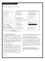
Purchase the Optional Installer’s Remote and Clone Programmer
To perform a normal installation set up, you need an installer’s remote such as the HP602, and the LT2000 Quickset II
Clone Programmer—both are shown and described in later sections. The installer remote allows access to the Installer
menus, User menus, and Source/Channel Bank keys. The installer remote has Menu, Select, and Adjust, and Channel Bank
Keys. The LT2000 Quickset II Clone Programmer is used to duplicate a TV’s setup and install it on another identical TV.
See your Zenith Dealer.
Design and specifications subject to change without prior notice.
Installer/Hospital Note:
Pages 40, 41, 42, 43, and 44 contain information and menus which the patient can use to operate
the TV. It is recommended that these four pages be copied and included with the literature packet
that the hospital provides to the patient.
206-3853
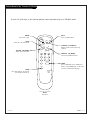
Optional Installer and Patient Remote Controls:
Shown herein are optional remote controls that can be used by the installer and the patient. Be
advise that these remote controls are NOT included with this TV. However, these remotes can be pur-
chased separately, see your Zenith dealer.
Use the steps outlined below as a setup guide and to determine the TV features
that will require adjustment for the needs of the end user

PAGE 6
206-3491-O
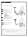
Mini glossary
75 OHM RF CABLE The wire that comes from an off-air antenna or cable service provider. Each end looks like a hex shaped nut with a wire
sticking through the middle, and it screws onto the threaded jack on the back of the TV.
A small device that connects a two-wire 300 ohm antenna to a 75 ohm RF jack. They are usually about an inch long with two screws
on one end and a round opening with a wire sticking out on the other end.
Antenna Hook Up
Connect an off-air antenna to the HealthView TV
If you have a 75 ohm RF cable, then you don’t need
any adapters.
A 300 to 75 ohm adapter is not included with the
Zenith HealthView TV.
300 TO 75 OHM
ADAPTER
ANTENNA
CABLE
M.P.I.
TV Back
Flat wire
(300 ohm)
Antenna
300/75 ohm
Adapter
TV Back Panel
(Expanded View)
PILLOW SPEAKER
TV
SPKR
PILLOW
SPKR
Video
In
Speaker
Out
Audio
In
ANTENNA
CABLE
M.P.I.
TV Back
Antenna
TV Back Panel
(Expanded View)
RF Coaxial Wire
(75ohm)
PILLOW SPEAKER
TV
SPKR
PILLOW
SPKR
Video
In
Speaker
Out
Audio
In
Locate the Antenna/Cable jack on the back of
the HealthView TV.
Connect the antenna wire that runs from the
wall to this jack, according to one of the dia-
grams shown to the right.
Remove the back of the optional remote and
put in two AA batteries.
Plug in the TV. The HealthView TV is designed
to operate on standard current, 120-volt 60
Hertz AC. Do not attempt to operate it on DC
power.
Go to page 11 to Auto Program the TV.
Back of
Remote
1
2
3
4
5

PAGE 7
206-3491-O
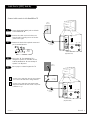
Cable Service (CATV) Hook Up
If you’re using a cable box, leave the TV on channel
3 or 4 and use the cable box to change channels.
If you’re using a cable box, Auto Program might
only find the channel the cable service is on (usual-
ly channel 3 or 4).
Cable TV
Wall Jack
RF Coaxial Wire
(75ohm)
ANTENNA
CABLE
M.P.I.
TV Back
TV Back Panel
(Expanded View)
PILLOW SPEAKER
TV
SPKR
PILLOW
SPKR
Video
In
Speaker
Out
Audio
In
Cable TV
Wall Jack
Cable Box
In
Out
RF Coaxial Wire
(75ohm)
3 4
output
switch
ANTENNA
CABLE
M.P.I.
TV Back
TV Back Panel
(Expanded View)
PILLOW SPEAKER
TV
SPKR
PILLOW
SPKR
Video
In
Speaker
Out
Audio
In
Locate the Antenna/Cable jack on the back
of the HealthView TV.
Connect the cable service wire that runs
from the wall, according to one of the dia-
grams to the right.
Remove the back of the optional remote and
put in two AA batteries.
Plug in the TV. The HealthView TV is
designed to operate on standard current,
120-volt 60 Hertz AC. Do not attempt to
operate it on DC power.
Go to page 11 to Auto Program the TV.
Back of
Remote
1
2
3
4
5
Connect cable service to the HealthView TV

PAGE 8
206-3491-O
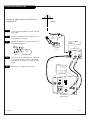
Antenna with VCR Hook Up
Connect an off-air antenna and VCR to the
HealthView TV
Locate the Antenna/Cable in jack on the back
of the VCR.
Connect the antenna wire according to one of
the diagrams to the right.
Remove the back of the optional remote and
put in two AA batteries.
Plug in the TV. The HealthView TV is designed
to operate on standard current, 120-volt 60
Hertz AC. Do not attempt to operate it on DC
power.
Go to page 11 to Auto Program the TV.
Back of
Remote
1
2
3
4
5
In
Out
Audio
Video
3 4
VCR Back
VCR Back AV Panel
output
switch
Round
Or
Flat wire
(300 ohm)
300/75 ohm
Adapter
TV Back
ANTENNA
CABLE
M.P.I.
TV Back Panel
(Expanded View)
PILLOW SPEAKER
TV
SPKR
PILLOW
SPKR
Video
In
Speaker
Out
Audio
In
Antenna

206-3684-A
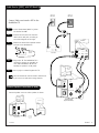
Cable Service (CATV) with VCR Hook Up
Connect Cable service and a VCR to the
HealthView TV
Leave the VCR and the television tuned to channel three
or four and use the cable box to change channels.
Locate the Antenna/Cable in jack on
the back of the VCR.
Connect the wire that runs from the
cable service wall jack, according to
one of the diagrams to the right.
Remove the back of the optional remote
and put in two AA batteries.
Plug in the TV. The HealthView TV is
designed to operate on standard cur-
rent, 120-volt 60 Hertz AC. Do not
attempt to operate it on DC power.
Go to page 11 to Auto Program the TV.
Back of
Remote
1
2
3
4
5
PAGE 9
In
Out
Audio
Video
3 4
VCR Back
VCR Back AV Panel
output
switch
TV Back
ANTENNA
CABLE
M.P.I.
TV Back Panel
(Expanded View)
PILLOW SPEAKER
TV
SPKR
PILLOW
SPKR
Video
In
Speaker
Out
Audio
In
Cable TV
Wall Jack
Cable Box
In
Out
3 4
output
switch
Cable TV
Wall Jack
External Speaker Connection (8-ohm)
TV Back
ANTENNA
CABLE
M.P.I.
TV Back Panel
(Expanded View)
PILLOW SPEAKER
TV
SPKR
PILLOW
SPKR
Video
In
Speaker
Out
Audio
In
A/V cables
not included
with TV
8-ohm Speaker In
Speaker Back
Connect Speaker out to an 8-ohm speaker as shown.

PAGE 10
206-3491-O
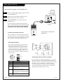
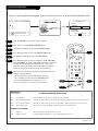
Pillow Speaker Hook Up
Locate the Pillow Speaker Output jack on the back
of the HealthView TV.
Connect an accessory pillow speaker or wired
remote control unit to this 6-pin jack.
Select PILLOW SPKR on the rear panel of the
HealthView TV.
Use a pillow speaker by Curbell, Model A-16455-02 or
other UL recognized pendant control bearing the warning:
“Risk of fire if used in oxygen enriched atmosphere.
Keep pendant control away from oxygen equipment.”
TV
TV Back
ANTENNA
CABLE
M.P.I.
TV Back Panel
(Expanded View)
PILLOW SPEAKER
TV
SPKR
PILLOW
SPKR
Video
In
Speaker
Out
Audio
In
1
2
Connect a pillow speaker to the HealthView TV
3
TV
ON/OFF
CHAN
DOWN
CHAN
UP
(MALE
PLUG)
VOLUME CONTROL
SPKR.
5
1
4
6
2
1
2
3
4
5
6
3
1
5
2
4
6
TV ON/OFF
OPEN
CHAN UP/DATA IN
COMMON
AUDIO OUT
CHAN DOWN
Controlling the TV with mechanical switches
Pin 4 (common) is momentarily connected to pin 1, 3, or 6 via
push-action switches to control On/Off and Channel Up/Down.
These pins are at +13 volts DC (when measured from pin 4) with
the switches open. Current draw is 8 mA when a switch is
closed. (This operation is identical to previous Zenith models
using the 5-Wire Interface except that only +7 volts DC was
supplied and current draw was only 2.5 mA.)
Pillow Speaker Interface
This connector furnishes three control lines and an
audio output. A patient-pendant remote control, or
entertainment audio and nurse call system may be
connected here. All lines are isolated from the AC
power line and earth ground. (Opto-isolators isolate
the control lines, and a transformer isolates the
audio. There are no relays or inductive components in
the control lines.)
Pin no. Purpose
1 External TV On/Off switch
2 (not used)
3 External Channel Up switch or Data in
4 Common connection for control, data,
and audio output.
Impedance to earth ground is a 10-meg resistor
in parallel with a 1100 pf capacitor.
5 Isolated audio output. Nominal 14-ohm source
impedance with short circuit protection. Intended
for a pillow speaker with a low-impedance pad-type
volume control.
6 External Channel Down switch
Pillow speaker not included with
HealthView TV.
3
Controlling the TV with Serial Data
The TV is capable of being controlled by a single-wire,
serial data signal. This is a Zenith patented technology
and is being implemented by certain brands of “smart”
pillow speakers, such as Curbell’s “GEN-II” models.

PAGE 11
206-3747
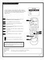
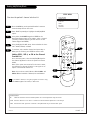
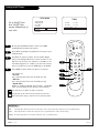
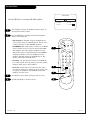
Auto Program (Channel Search)
Use Auto Program to specify Cable TV or Off Air Antenna
incoming signal source and automatically store in the mem-
ory of the TV, all of the channels that are found by the
channel search
With the optional Installer remote control in hand, press
the POWER key to turn on the HealthView TV.
Press the MENU key to show the Setup menu.
Using SELECT on the remote control, highlight Auto
Program on the screen.
Press the Right or Left ADJ (Adjust) arrow to go to the
Auto Program menu.
Using SELECT, choose either Cable TV or Off Air Antenna
on the screen.
Press the Right or Left ADJ arrow to begin the Channel
Search.
Press ENTER when the channel search is complete.
1
2
3
4
5
6
7
123
456
7
0
8
ENTER
9
POWER
TV/FM
FLSHBK
MUTE
VOLUME
CHANNEL
MENU
ADJ ADJ
SELECT
TIMER
BANK
CH PREVIEW
BED 1
BED 2
CC
-
+
-
+
3/5
AUTO PROGRAM
ADD/DEL/BLNK
CH. LABELS
CLOCK SET
TIMER
CAPTIONS
LANGUAGE
Mini glossary
OFF AIR ANTENNA If the patient can only view over-the-air broadcasts, select Antenna.
CABLE If you provide cable service to the patients, select Cable.
Auto Program finds channels being received by the TV tuner.
Cable will not work unless the hospital provides a cable service.
4/6
1
7
2
Optional Installer and Patient Remote Controls:
Shown herein are optional remote controls that can be used by the
installer and the patient. Be advise that these remote controls are
NOT included with this TV. However, these remotes can be purchased
separately, see your Zenith dealer.

PAGE 12
206-3491-O
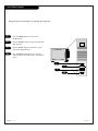
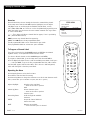
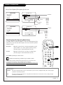
Front Panel Controls
power
channel
volume
captions
4
Press the POWER button to turn on the
HealthView TV.
Use the CHANNEL button to cycle through avail-
able channels.
Use the VOLUME button to adjust the sound
level of the HealthView TV.
Press CAPTIONS repeatedly to turn selected
closed captions option On or Off. (See Captions
page.)
Using the front control panel to operate the television
1
2
3
2
3
1
4

PAGE 13
206-3853
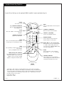
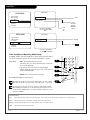
Installer Remote Key Functions
123
456
7
0
8
ENTER
9
POWER
TV/FM
FLSHBK
MUTE
VOLUME
CHANNEL
MENU
ADJ ADJ
SELECT
TIMER
BANK
CH PREVIEW
BED 1
BED 2
CC
-
+
-
+
FLASHBK (FLASHBACK)
Return to the last channel viewed.
POWER
Turns TV On or Off
.
CHANNEL (UP/DOWN)
Tunes to next available channel.
MUTE
Turns sound Off and On, while the picture
remains.
ENTER
Press to view the Channel/Time display or
to remove any on-screen display or menu.
NUMBER KEYPAD
Selects channels directly and enters
numeric values for some options
.
remote control part number
HP602
124-213-06
TIMER
Press repeatedly to adjust TV turn-off time
up to 4-hours.
Use to pick AM/PM in Clock menu.
VOLUME LEFT/RIGHT
Adjusts the sound levels.
CC (CLOSED CAPTIONING)
Press to access closed captions.
Press ENTER to exit.
A quick list of the keys on the optional HP602 installer’s remote and what they do
BANK
Press and repeat to select a Channel
Memory Bank - - 1, 2, 3, or 4 (standby).
MENU/SELECT/ADJ (ADJUST)
Press MENU repeatedly to scroll through
either the Installer, or User menus. Use
SELECT to choose an option and ADJ
(adjust) to change the selected option.
CHANNEL PREVIEW
Gives installer access to the patient’s
menus. Displays the available TV channels
and patient’s Parental Control menu.
TV/FM
Selects TV or Radio on TVs equipped with
FM radio.
BED 1/BED 2 (*See Note Below)
Determines the code set transmitted, Bed
1 or Bed 2. Switch setting must corre-
spond to item 27, HOSPITAL MODE setting
in the TV’s Installer Menu.
*Note: Bed 1 - Bed 2 switch on installer/patient remote. The position of the Bed 1 -
Bed 2 switch must correspond to the setting in the Installer’s menu. The switch above
can be set by sliding it to the Bed 1 or Bed 2 position. On the patients’ remote, the Bed
1 or Bed 2 position can be selected by using a paper clip or a ball-point pen to slide
the switch to the correct position.
Left position = Bed 1.
Right Position = Bed 2.

PAGE 14
206-3491-O
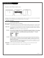
On-Screen Menus Overview
ON-SCREEN MENUS
Setup Menu Adjusts the basic characteristics of the TV
Auto Program 11 Automatically finds and stores active channels to scroll through using Channel Up/Down.
Add/Del/Blnk 15 Manually choose which active channels will appear when using Channel Up/Down.
Channel Labels 16 Labels the channels with their network names (ABC, CBS, HBO, etc.) or create custom names.
Clock Set 17 Sets the time.
On/Off Timers 18 Set the timers to automatically turn the TV On/Off each day at the preset time(s).
Captions 19 Chooses the captioning or text option.
Language 20 Chooses the language the on-screen menus will appear in.
Video Menu 21 Adjusts the picture appearance. The options are: Contrast, Brightness, Color, Tint, Sharpness,
Picture Pref.
FM Radio Menu 22 Adjusts the FM Radio options.
Parental Control 24 Allows installer to restrict viewable programming for up to 99 hours, with the use
of a password.
26 OTHER MENUS AND ON-SCREEN DISPLAYS
Channel/Time Shows the current time, selected channel and XDS* data if available.
Sleep Timer Sets the time the TV will turn off.
Volume Shows current sound level.
Captions Sets Caption/Text options.
Ch Preview Displays the available channels list.
Channel Bank Shows currently selected channel bank.
Inactive TV Prompts the patient to arrange for TV service.
INSTALLER MENUS 30 Sets up the TV’s operating features.
*XDS (Extended Data Service) Additional program information provided at the
discretion of the broadcaster. May include: title of broadcast, length of broadcast, and time
remaining until end of broadcast.
Descriptions of the menus on the TV
Using the Menu button on the optional installer’s remote, the installer can access all the menus below.
Menu Name Page Description

PAGE 15
NOAUX3684
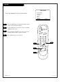
Fine-tune the patient’s channel selection list
Setting Add/Delete/Blank
Press the MENU key on the optional Installer’s remote to
show the Setup menu on the screen.
Press SELECT repeatedly to highlight the Add/Del/Blnk
option.
Using either the NUMBER keypad and ENTER or the
Channel Up/Down arrows on the remote, select a channel.
(If adding a deleted channel, you will need to use the
number keypad and ENTER.)
Using the Right/Left ADJ arrow, choose whether the chan-
nel is Added, Deleted, or Blank.
To continue, select another channel and repeat Step 3.
When you are finished, press ENTER to remove menu.
Adding VCR 3, VCR 4, or FM to the Channel
Preview List
Go to the Setup menu, select the Add/Del/Blnk option.
Use Channel Up/Down to select the option and choose
Added.
Note: If the option was turned off in the Service menu,
you will have to reinstate it before it can appear as an
option in the Channel Preview list.
Note: You can elect to Add, Delete or Blank: VCR 3 and
VCR 4. FM can be Added or Deleted, but not Blanked.
1
2
3
4
5
123
456
7
0
8
ENTER
9
POWER
TV/FM
FLSHBK
MUTE
VOLUME
CHANNEL
MENU
ADJ ADJ
SELECT
TIMER
BANK
CH PREVIEW
BED 1
BED 2
CC
-
+
-
+
2
AUTO PROGRAM
ADD/DEL/BLNK
CH. LABELS
CLOCK SET
TIMER
CAPTIONS
LANGUAGE
CH 44 ADDED
SETUP MENU
Mini glossary
ADD Adds new channels to the list that the patient can scroll through when using the remote.
DELETE Removes channels for one reason or another from the list that the patient can scroll through.
BLANK Removes the video signal from a channel so the patient will only receive the audio signal.
4
3/5
1
If you delete a channel, it isn’t gone for good. Just select it using
the NUMBER keypad on the remote, or add it later.
3
3

PAGE 16
206-3491-O
Setting Up Channel Labels
123
456
7
0
8
ENTER
9
POWER
TV/FM
FLSHBK
MUTE
VOLUME
CHANNEL
MENU
ADJ ADJ
SELECT
TIMER
BANK
CH PREVIEW
BED 1
BED 2
CC
-
+
-
+
AUTO PROGRAM
ADD/DEL/BLNK
CH. LABELS
CLOCK SET
TIMER
CAPTIONS
LANGUAGE
CH 32 ABC
SETUP MENU
Overview
Channel Labels help the user identify the channel or network being viewed.
In the Setup menu with the CH LABELS option highlighted, use the Adjust
Left/Right arrows to scroll through the available channel labels, such as,
A & E, AMC, ESPN, HBO, etc. These are a series of alphabetically organized preset
labels from which you can choose the more common networks. Use any of these
or create custom labels.
- - - - , The 4 dashes will allow a channel label to appear; if one is provided by
XDS. (Extended Data Service)
NONE, prevents any channel label from appearing.
LAB 1, thru LAB 20, are the 20 programmable labels.
The 20 programmable labels can be customized for your needs.
Each programmable label has 5 characters spaces available.
To Program a Channel Label
First select a channel using the NUMBER keypad and ENTER or the Channel
Up/Down arrows, on the optional Installer’s remote control.
(To select a deleted channel, use the NUMBER keypad and ENTER.)
To program a channel label, go to the Setup menu and select CH LABELS.
Press the Right/Left adjust arrow to scroll the available preset labels. Scroll past -
- - -, scroll past NONE, to go to the first programmable label slot, LAB 1. Notice
that the label appears with the title LAB 1, and is also on a dark background;
which will distinguish it from the preset labels.
Operating the Menu
Use Volume Up/Down to select the first letter.
Press MUTE to clear the label if necessary.
Use Channel Up/Down to change the character to one of the 255 characters avail-
able. (A blank letter space is available if required, after the “!” symbol.)
Adjust Left/Right Switches to the next label.
- - moves to the next or previous
label.
Volume Up/Down Selects character spaces
- - moves to the next or previous
character space.
Channel Up/Down Scrolls through the available
characters.
ENTER Accept the channel label and
removes the menu.
MUTE Removes current label,
- - if first character space is selected.

Mini glossary
TIME A four-digit figure broken down into hours and minutes, used to enter the current time when setting the clock or wake-up alarm.
HOURS First two digits that are entered when setting the clock or the wake-up alarm.
MINUTES The last two digits that are entered when setting the clock, or the wake-up alarm.
TIMER Chooses AM or PM when setting the clock.
PAGE 17
206-3747
The clock can also be set using 24 hour “military time.” For p.m. settings
add 1200. For example, to set 6:30 p.m., add 1200 to 630, = enter 1830.
For Auto Clock Set to work, TV must be tuned to a channel that has XDS
data available. Auto Clock Set, sets the time only once while the TV is on.
To set the clock with XDS data, turn TV off, then back on again, or set the
clock time manually.
Clock Set
123
456
7
0
8
ENTER
9
MENU
ADJ ADJ
SELECT
TIMER
BANK
CH PREVIEW
BED 1
BED 2
3
5
3
4
AUTO
EASTERN
CENTRAL
MOUNTAIN
PACIFIC
CLOCK MENU
CLOCK SET
TIME ZONE
DAY. SAVING
AUTO
AUTO
OFF
ON
10:43 AM
CLOCK MENU
CLOCK SET
TIME SET
MANUAL
TIMER
AUTO PROGRAM
ADD/DEL/BLNK
CH. LABELS
CLOCK SET
TIMER
CAPTIONS
LANGUAGE
SETUP MENU
TO SET CLOCK
AUTO PROGRAM
ADD/DEL/BLNK
CH. LABELS
CLOCK SET
TIMER
CAPTIONS
LANGUAGE
SETUP MENU
TO SET CLOCK
USE SELECT TO CHOOSE
USE ADJ TO CHANGE
USE SELECT TO CHOOSE
USE ADJ TO CHANGE
Clock Auto/Manual Operating Modes Setup
Use MENU, SELECT, and ADJ Left/Right to choose the Clock menu and to
set up the clock menu options, with the optional Installer’s remote.
Clock Mode Auto: TV automatically sets the time.
Time Zone: User can choose the time zone or have the
TV set it automatically.
Day. Savings: User can choose to have daylight
savings adjust the clock time one hour, or have the TV
adjust it automatically.
Manual: User sets the time on the clock.
Use ENTER repeatedly to remove menus.
2
1

PAGE 18
206-3747
123
456
7
0
8
ENTER
9
POWER
TV/FM
FLSHBK
MUTE
VOLUME
CHANNEL
MENU
ADJ ADJ
SELECT
TIMER
BANK
CH PREVIEW
BED 1
BED 2
CC
-
+
-
+
Set up On/Off Timers
Note: On/Off Timers
operate independently of
each other.
On the optional HP602 Installer’s remote, press MENU
repeatedly until the Setup menu appears.
Press SELECT repeatedly to highlight the Timer option, press
the Right arrow.
Use SELECT to choose an option. Use the number keypad
and/or the Left/Right ADJ arrows to enter the times. To set
PM, add 12 to the hours. For example, to set 6:00 p.m. Use
the number keypad to set 1-8-0-0. (6 for the hours and the
extra 12 for PM.) Do not use the TIMER key to set AM/PM.
Press ENTER to remove menu and return to TV viewing.
Your options are:
• On Time
Sets a time that the TV will turn itself On each day.
• Off Time
Sets a time that the TV will turn itself Off each day.
• On/Off Timer
Enables or disables the On/Off Timer functions. (The On/Off
Timer can be disabled but the settings will be retained.)
AUTO PROGRAM
ADD/DEL/BLNK
CH. LABELS
CLOCK SET
TIMER
CAPTIONS
LANGUAGE
TO SET TIMER
SETUP MENU
The clock must be set before the Timers will function.
The Off Timer can be used to turn the TV off at the preset time.
Note: No On Timer setting is required to use the Off Timer feature.
Mini glossary
TIME A four-digit figure broken down into hours and minutes, used to enter the time when setting the clock or programming timers.
HOURS First two digits that are entered when setting the clock or programming timers. (Add 12 for PM settings.)
MINUTES The last two digits that are entered when setting the clock, or programming timers.
ON TIME 9:00 AM
OFF TIME 7:00 PM
ON/OFF TIMER
ON
TIMER
Setting On/Off Timers
2
1
4
1
2
3
4
2/3
3
3

PAGE 19
206-3747
Standard closed captioning is available using the Caption 1 option.
Captions (Captions/Text)
CAPTION 1
CAPTION 2
CAPTION 3
CAPTION 4
TEXT 1
TEXT 2
TEXT 3
TEXT 4
OFF
CAPTIONS SETUP
OPER. MODE
SEL. TYPE
CAPTION LOCK
CC
CC
PRESS SELECT TO CHOOSE
PRESS ADJ TO CHANGE
STANDARD
ON, OFF
CC
CAPTION 1
CAPTION 2
CAPTION 3
CAPTION 4
TEXT 1
TEXT 2
TEXT 3
TEXT 4
TO SET CAPTIONS
CAPTIONS SETUP
OPER. MODE
SEL. TYPE
CAPTION
ON MUTE
CAPTION LOCK
CC
PRESS SELECT TO CHOOSE
PRESS ADJ TO CHANGE
QUICK/MUTE
ON, OFF
ON, OFF
ON, OFF
AUTO PROGRAM
ADD/DEL/BLNK
CH. LABELS
CLOCK SET
TIMER
CAPTIONS
LANGUAGE
SETUP MENU
TO SET CAPTIONS
AUTO PROGRAM
ADD/DEL/BLNK
CH. LABELS
CLOCK SET
TIMER
CAPTIONS
LANGUAGE
SETUP MENU
123
456
7
0
8
ENTER
9
POWER
TV/FM
FLSHBK
MUTE
VOLUME
CHANNEL
MENU
ADJ ADJ
SELECT
TIMER
BANK
CH PREVIEW
BED 1
BED 2
CC
-
+
-
+
1
2
Mini glossary
CAPTIONS The term for the words that scroll across the bottom of your TV screen; usually the audio portion of the program
provided for the hearing impaired.
TEXT The term for the words that appear in a large black frame and almost cover the entire screen; usually messages
provided by the broadcaste
r.
Set up Closed Caption/Text options for the user
Closed Captions/Text Operating Modes Setup
Use MENU, SELECT, and ADJ Left/Right to choose the Closed Captions/Text
mode and to set up the other menu options for the user with the optional
Installer’s remote.
Quick/Mute When CC is pressed: User can only turn Captions on/off.
(If CC on Mute is on, shows captions option on mute.)
(If locked, type is retained with Power on/off.)
Standard When CC is pressed: User can choose a captions type.
(If locked, type is retained with Power on/off.)
Press ENTER repeatedly to remove menus.
Caption/Text are features which allow the Concierge TV to receive the closed
caption and/or text options if made available by the broadcaster.
Availability and functionality of Caption/Text options are determined only by each
broadcaster and may not be available in your area.

PAGE 20
206-3491-O
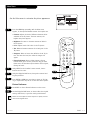
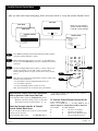
Language
AUTO PROGRAM
ADD/DEL/BLNK
CH. LABELS
CLOCK SET
TIMER
CAPTIONS
LANGUAGE
ENGLISH
SETUP MENU
123
456
7
0
8
ENTER
9
POWER
TV/FM
FLSHBK
MUTE
VOLUME
CHANNEL
MENU
ADJ ADJ
SELECT
TIMER
BANK
CH PREVIEW
BED 1
BED 2
CC
-
+
-
+
2
1
4
Choose the language for the on-screen menus
Press the MENU key on the optional Installer’s remote
control so the Setup menu appears.
Use the SELECT key on the remote control, to highlight
Language on the screen.
Press the Right/Left ADJ arrow to choose one of the
following options: English, Spanish or French.
Press ENTER to return to TV viewing.
1
2
3
4
3
La pagina sta caricando ...
La pagina sta caricando ...
La pagina sta caricando ...
La pagina sta caricando ...
La pagina sta caricando ...
La pagina sta caricando ...
La pagina sta caricando ...
La pagina sta caricando ...
La pagina sta caricando ...
La pagina sta caricando ...
La pagina sta caricando ...
La pagina sta caricando ...
La pagina sta caricando ...
La pagina sta caricando ...
La pagina sta caricando ...
La pagina sta caricando ...
La pagina sta caricando ...
La pagina sta caricando ...
La pagina sta caricando ...
La pagina sta caricando ...
La pagina sta caricando ...
La pagina sta caricando ...
La pagina sta caricando ...
La pagina sta caricando ...
La pagina sta caricando ...
La pagina sta caricando ...
La pagina sta caricando ...
La pagina sta caricando ...
-
 1
1
-
 2
2
-
 3
3
-
 4
4
-
 5
5
-
 6
6
-
 7
7
-
 8
8
-
 9
9
-
 10
10
-
 11
11
-
 12
12
-
 13
13
-
 14
14
-
 15
15
-
 16
16
-
 17
17
-
 18
18
-
 19
19
-
 20
20
-
 21
21
-
 22
22
-
 23
23
-
 24
24
-
 25
25
-
 26
26
-
 27
27
-
 28
28
-
 29
29
-
 30
30
-
 31
31
-
 32
32
-
 33
33
-
 34
34
-
 35
35
-
 36
36
-
 37
37
-
 38
38
-
 39
39
-
 40
40
-
 41
41
-
 42
42
-
 43
43
-
 44
44
-
 45
45
-
 46
46
-
 47
47
-
 48
48


Zenith HealthView H20F50DT Manuale utente
- Tipo
- Manuale utente
in altre lingue
Documenti correlati
-
Zenith HE20D50DT Installation And Operating Manual, Warranty
-
-
-
-
-
-
Zenith Concierge H25C39Y Installation And Operating Manual, Warranty
-
-
-