Zenith Concierge H2035DT Installation And Operating Manual, Warranty
- Categoria
- TV LCD
- Tipo
- Installation And Operating Manual, Warranty
Questo manuale è adatto anche per

Concierge
TM
Direct-View
Television
Receiver with
FM Radio
machine numbers H2035DT H2535DT
installation & operating guide / warranty

RECORD YOUR MODEL NUMBER
The model and serial number of your new TV are located
on the back of the TV cabinet. For your future convenience,
we suggest that you record these numbers here:
MODEL NO.____________________________________
SERIAL NO.____________________________________
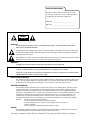
WARNING:
TO REDUCE THE RISK OF ELECTRIC SHOCK DO NOT REMOVE COVER (OR BACK). NO USER SERVICEABLE PARTS INSIDE.
REFER TO QUALIFIED SERVICE PERSONNEL.
The lightning flash with arrowhead symbol, within an equilateral triangle, is intended to alert the user to the presence
of uninsulated “dangerous voltage” within the product’s enclosure that may be of sufficient magnitude to constitute a
risk of electric shock to persons.
The exclamation point within an equilateral triangle is intended to alert the user to the presence of important operating
and maintenance (servicing) instructions in the literature accompanying the appliance.
WARNING:
TO PREVENT FIRE OR SHOCK HAZARDS, DO NOT EXPOSE THIS PRODUCT TO RAIN OR MOISTURE.
POWER CORD POLARIZATION:
CAUTION: TO PREVENT ELECTRIC SHOCK, MATCH WIDE BLADE OF PLUG TO WIDE SLOT, FULLY INSERT.
ATTENTION: POUR ÉVITER LES CHOCS ÉLECTRIQUES, INTRODUIRE LA LAME LA PLUS LARGE DE LA FICHE DANS LA BORNE
CORRESPONDANTE DE LA PRISE ET POUSSER JUSQU’AU FOND.
NOTE TO CABLE/TV INSTALLER:
This reminder is provided to call the cable TV system installer’s attention to Article 820-40 of the National Electric Code
(U.S.A.). The code provides guidelines for proper grounding and, in particular, specifies that the cable ground shall be
connected to the grounding system of the building, as close to the point of the cable entry as practical.
REGULATORY INFORMATION:
This equipment has been tested and found to comply with the limits for a Class B digital device, pursuant to Part 15
of the FCC Rules. These limits are designed to provide reasonable protection against harmful interference when the
equipment is operated in a residential installation. This equipment generates, uses and can radiate radio frequency
energy and, if not installed and used in accordance with the instruction manual, may cause harmful interference to radio
communications. However, there is no guarantee that interference will not occur in a particular installation. If this
equipment does cause harmful interference to radio or television reception, which can be determined by turning
the equipment off and on, the user is encouraged to try to correct the interference by one or more of the following
measures:
• Reorient or relocate the receiving antenna.
• Increase the separation between the equipment and receiver.
• Connect the equipment into an outlet on a circuit different from that to which the
receiver is connected.
• Consult the dealer or an experienced radio/TV technician for help.
CAUTION:
Do not attempt to modify this product in any way without written authorization from Zenith Electronics Corporation.
Unauthorized modification could void the user’s authority to operate this product.
WARNING
RISK OF ELECTRIC SHOCK
DO NOT OPEN
Concierge is a trademark of Zenith Electronics Corporation © Copyright 1999 Zenith Electronics Corporation

PAGE 3
206-3489-O
1. Read Instructions
All the safety and operating instructions should be read
before the product is operated.
2. Follow Instructions
All operating and use instructions should be followed.
3. Retain Instructions
The safety and operating instructions should be retained for
future reference.
4.Heed Warnings
All warnings on the product and in the operating instruc-
tions should be adhered to.
5. Cleaning
Unplug this product from the wall outlet before cleaning.
Do not use liquid cleaners or aerosol cleaners. Use a damp
cloth for cleaning.
6. Water and Moisture
Do not use this product near water for example, near a
bath tub, wash bowl, kitchen sink, or laundry tub, in a wet
basement, or near a swimming pool.
7. Accessories
Do not place this product on an unstable cart, stand, tri-
pod, bracket, or table. The product may fall, causing serious
injury to a child or adult, and serious damage to the prod-
uct. Use only with a cart, stand, tripod, bracket, or table
recommended by the manufacturer, or sold with the prod-
uct. Any mounting of the product should follow the manu-
facturer’s instructions, and should use a mounting accesso-
ry recommended by the manufacturer.
8. Transporting Product
A product and cart combination should be moved with care.
Quick stops, excessive force, and uneven surfaces may
cause the product and cart combination to overturn.
9. Attachments
Do not use attachments not recommended by the product
manufacturer as they may cause hazards.
10. Ventilation
Slots and openings in the cabinet are provided for ventila-
tion and to ensure reliable operation of the product and to
protect it from overheating, and these openings must not
be blocked or covered. The openings should never be
blocked by placing the product on a bed, sofa, rug, or
other similar surface. This product should not be placed in
a built-in installation such as a bookcase or rack unless
proper ventilation is provided or the manufacturer’s instruc-
tions have been adhered to.
11. Power Sources
This product should be operated only from the type of
power source indicated on the marking label. If you are not
sure of the type of power supply to your home, consult
your product dealer or local power company. For products
intended to operate from battery power, or other sources,
refer to the operating instructions.
12. Line-Cord Polarization
This product is equipped with a polarized alternating-cur-
rent line plug (a plug having one blade wider than the
other). This plug will fit into the power outlet only one
way. This is a safety feature. If you are unable to insert the
plug fully into the outlet, try reversing the plug. If the
plug should still fail to fit, contact your electrician to
replace your obsolete outlet. Do not defeat the safety pur-
pose of the polarized plug.
13. Power-Cord Protection
Power-supply cords should be routed so that they are not
likely to be walked on or pinched by items placed upon or
against them, paying particular attention to cords at plugs,
convenience receptacles, and the point where they exit
from the product.
Important safeguards for you and your new product
Your product has been manufactured and tested with your safety in mind. However, improper use can result in potential
electrical shock or fire hazards. To avoid defeating the safeguards that have been built into your new product, please read
and observe the following safety points when installing and using your new product, and save them for future reference.
Observing the simple precautions discussed in this booklet can help you get many years of enjoyment and safe operation
that are built into your new product.
This product complies with all applicable U.S. Federal safety requirements, and those of the Canadian Standards Association.
(Continued on next page)
IMPORTANT SAFETY INSTRUCTIONS

(Continued from previous page)
14. Outdoor Antenna Grounding
If an outside antenna or cable system is connected to the
product, be sure the antenna or cable system is grounded so
as to provide some protection against voltage surges and
built-up static charges. Article 810 of the National Electrical
Code (U.S.A.), ANSI/ NFPA 70 provides information with
regard to proper grounding of the mast and supporting
structure, grounding of the lead-in wire to an antenna dis-
charge unit, size of grounding conductors, location of
antenna-discharge unit, connection to grounding electrodes,
and requirements for the grounding electrode.
15. Lightning
For added protection for this product (receiver) during a
lightning storm, or when it is left unattended and unused
for long periods of time, unplug it from the wall outlet and
disconnect the antenna or cable system. This will prevent
damage to the product due to lightning and power-line
surges.
16. Power Lines
An outside antenna system should not be located in the
vicinity of overhead power lines or other electric light or
power circuits, or where it can fall into such power lines or
circuits. When installing an outside antenna system,
extreme care should be taken to keep from touching such
power lines or circuits as contact with them might be fatal.
17. Overloading
Do not overload wall outlets and extension cords as this can
result in a risk of fire or electric shock.
18. Object and Liquid Entry
Never push objects of any kind into this product through
openings as they may touch dangerous voltage points or
short-out parts that could result in a fire or electric shock.
Never spill liquid of any kind on the product.
19. Servicing
Do not attempt to service this product yourself as opening
or removing covers may expose you to dangerous voltage or
other hazards. Refer all servicing to qualified service person-
nel.
20. Damage Requiring Service
Unplug this product from the wall outlet and refer servicing
to qualified service personnel under the following condi-
tions:
a. If the power-supply cord or plug is damaged.
b. If liquid has been spilled, or objects have fallen into the
product.
c. If the product has been exposed to rain or water.
d. If the product does not operate normally by following
the operating instructions. Adjust only those controls that
are covered by the operating instructions as an improper
adjustment of other controls may result in damage and will
often require extensive work by a qualified technician to
restore the product to its normal operation.
e. If the product has been dropped or the cabinet has been
damaged.
f. If the product exhibits a distinct change in performance.
21. Replacement Parts
When replacement parts are required, be sure the service
technician has used replacement parts specified by the man-
ufacturer or have the same characteristics as the original
part. Unauthorized substitutions may result in fire, electric
shock, or other hazards.
22. Safety Check
Upon completion of any service or repairs to this product,
ask the service technician to perform safety checks to deter-
mine that the product is in proper operating condition.
23. Wall or Ceiling Mounting
The product should be mounted to a wall or ceiling only as
recommended by the manufacturer.
24. Heat
The product should be situated away from heat sources such
as radiators, heat registers, stoves, or other products
(including amplifiers) that produce heat.
PAGE 4
206-3489-O
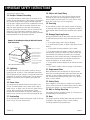
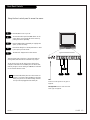
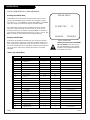
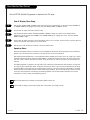
Antenna Lead in Wire
Antenna Discharge Unit
(NEC Section 810-20)
Grounding Conductor
(NEC Section 810-21)
Ground Clamps
Power Service Grounding
Electrode System (NEC
Art 250, Part H)
Ground Clamp
Electric Service
Equipment
Example of Grounding According to National Electrical
Code Instructions
NEC - National Electrical Code
IMPORTANT SAFETY INSTRUCTIONS

206-3488-O
PAGE 5
Table of Contents
Turn to the next page to begin the TV setup
Safety Warnings 2
Important Safety Information 3
Table of Contents 5
Step 1. Hook Up TV
Hookup Directory 6
TV and other Equipment Hookups
Antenna 7
Cable service 8
Antenna with VCR 9
Cable service with VCR 10
External Speaker 11
Step 2. Channel Search and Reception Setup
Auto Program 12
(Select Antenna, or cable service and perform
channel search)
Front Panel Controls 13
Guest’s Remote Key Functions 14
Installer’s Remote Key Functions 15
On-Screen Menus Overview 16
Step 3. Customize the TV’s Features
Setup Menu (Start with page 12, Auto Program)
Add/Del/Blank 17
Channel Labels 18
Timer Setup 19
Clock Set 20
Captions Caption/Text 21
Language 22
Audio Menu 23
Bass, Treble, Balance, Audio Mode,
Front Surround, Sound Rite, Speakers
Video Menu 24
Contrast, Brightness, Color, Tint, Sharpness,
Picture Pref.
Installer Parental Control Menu 25
Setup Parental Control
Other Menus and On-Screen Displays 27
FM Radio
FM Radio Auto Program 28
FM Radio On-Screen Menus 29
FM Radio Audio Menu 30
Channel Banks
Managing the Channel Banks 31
Installer Menus
Installer Menus 34
LT1500 Quickset Clone Programmer 37
Maintenance 40
Trouble Shooting 41
Glossary 42
Guest Operation Section (Copy for guest usage)
Guest Remote Control Key Functions 43
Guest Parental Control Menu 44
Guest Menus and On-Screen Displays 46
Guest FM Radio Operation/Menus 47
Warranty for Concierge
TM
Series TVs Back Cover
Purchase the Optional Installer’s Remote and Clone Programmer
To preform the installation setup, you need an installer’s remote like the LP702, and the LT1500 Clone Programmer - -
both are shown and described in later sections. The installer remote allows access to the Installer Menus, User menus,
and Source/Channel Banks. The installer remote has Menu, Select, and Adjust Keys (Up/Down/Left/Right arrows) and
Source/Channel Bank Keys. The LT1500 Clone Programmer is used to duplicate a TV’s setup and install it on another TV.
See your Zenith Dealer.
Installer/Hotel Note:
Pages 43, 44, 45, 46, and 47 contain information and menus which the guest can use to operate the
TV and FM Radio. It is recommended that these five pages be copied and included with the literature
packet that the hotel provides to the guest.
Design and specifications are subject to change without prior notice.

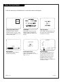
If you are using an antenna and no other equipment, go to . . . . . . . . . . . . . . . . . . page 7
If you have cable and no other equipment, go to . . . . . . . . . . . . . . . . . . . . . . . . . page 8
If you are using an antenna and have a VCR, go to . . . . . . . . . . . . . . . . . . . . . . . page 9
If you have cable and a VCR, go to . . . . . . . . . . . . . . . . . . . . . . . . . . . . . . . . . . page 10
If you want to connect a Matrix speaker, go to . . . . . . . . . . . . . . . . . . . . . . . . . . .page 11
206-3489-O
PAGE 6
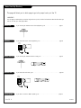
Basic Hook-Up Directory
This page will direct you to which page to go to for proper hook up of the TV
IMPORTANT!!
Use this page to decide where you need to begin the set up. First, find the line below that best describes what you
want to do, then go to that page number.
Cable TV
wall jack
Cable box
In
Out
Cable TV
wall jack
Cable box
In
Out
Antenna only
Cable only
Antenna with VCR
Cable and VCR
External Speaker

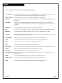
Mini glossary
75 OHM RF CABLE The wire that comes from an off-air antenna or cable service provider. Each end looks like a hex shaped nut with a wire
sticking through the middle, and it screws onto the threaded jack on the back of your TV.
A small device that connects a two-wire 300 ohm antenna to a 75 ohm RF jack. They are usually about an inch long with two screws
on one end and a round opening with a wire sticking out on the other end.
206-3489-O
PAGE 7
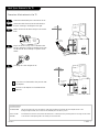
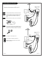
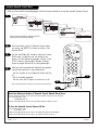
Hook Up an Antenna to the TV
Connect an off-air antenna to the TV
If you have a 75 ohm RF cable, then you don’t need
any adapters!
A 300 to 75 ohm adapter is not included with the
Zenith TV.
300 TO 75 OHM
ADAPTER
ANTENNA
CABLE
M.P.I.
TV back
Flat wire
(300 ohm)
Antenna
300/75 ohm
Adapter
TV back panel
(expanded view)
R- AUDIO- L
VIDEO
IN
MATRIX
OUT
IN
TV back
TV back panel
(expanded view)
ANTENNA
CABLE
M.P.I.
RF coaxial wire
(75ohm)
Antenna
R- AUDIO- L
VIDEO
IN
MATRIX
OUT
IN
Locate the Antenna/Cable jack on the back of the TV.
Connect the cable that runs from the wall directly to
this jack, according to the diagram to the right.
Remove the back of the remote and put in two AA bat-
teries.
Plug in the TV. Do not plug it into a switched outlet.
The TV is designed to operate on standard current, 120-
volt 60 Hertz AC. Do not attempt to operate it on DC
Current.
Go to page 12 to Auto Program the TV.
back of
remote
1
2
3
4
5

206-3489-O
PAGE 8
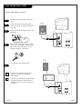
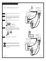
Hook Up Cable Service (CATV)
If you’re using a cable box, leave the TV on
channel 3 or 4 and use your cable box to
change channels.
If you’re using a cable box, Auto Program might
only find the channel your cable service is on
(usually channel 3 or 4). Don’t worry, that’s all
you need!
Cable TV
wall jack
RF coaxial wire (75ohm)
TV back
ANTENNA
CABLE
M.P.I.
R- AUDIO- L
VIDEO
IN
MATRIX
OUT
IN
ANTENNA
CABLE
M.P.I.
Cable TV
wall jack
Cable box
In
Out
RF coaxial wire (75ohm)
3 4
output
switch
TV back
R- AUDIO- L
VIDEO
IN
MATRIX
OUT
IN
Locate the Antenna/Cable jack on the back of
the TV.
Connect the cable that runs from the wall
directly to this jack, according to the diagram
to the right.
Remove the back of the remote and put in two
AA batteries.
Plug in the TV. Do not plug it into a switched
outlet. Your TV is designed to operate on stan-
dard current, 120-volt 60 Hertz AC. Do not
attempt to operate it on DC Current.
Go to page 12 to Auto Program the TV.
back of
remote
1
2
3
4
5
Connect cable service to the TV

206-3489-O
PAGE 9
Hook Up Antenna and VCR to the TV
Connect an off-air antenna and VCR to the TV
No A/V cables are included with the Zenith TV.
Without A/V cables, most VCRs will not play videocas-
settes in stereo sound.
Flat wire
(300 ohm)
Antenna
300/75 ohm
Adapter
In
Out
Audio
Video
3 4
VCR back
VCR back AV panel
output
switch
ANTENNA
CABLE
M.P.I.
TV back panel
(expanded view)
A/V cables
not included
with TV
TV back
R- AUDIO- L
VIDEO
IN
MATRIX
OUT
IN
TV back
RF coaxial wire
(75ohm)
not included
with TV
RF coaxial wire
(75ohm)
Antenna
A/V cables
not included
with TV
R- AUDIO- L
VIDEO
IN
MATRIX
OUT
IN
In
Out
Audio
Video
3 4
VCR back
VCR back AV panel
output
switch
ANTENNA
CABLE
M.P.I.
TV back panel
(expanded view)
TV back
Locate the Antenna/Cable jack on the back of the VCR.
Connect the cable that runs from the antenna directly to
this jack, according to the diagram to the right. As
required, make the other connections as shown to the
right.
Remove the back of the remote, put in two AA batteries.
Plug in the TV. Do not plug it into a switched outlet. The
TV is designed to operate on standard current, 120-volt
60 Hertz AC. Do not attempt to operate it on DC Current.
Go to page 12 to Auto Program the TV.
back of
remote
1
2
3
4
5

PAGE 10
206-3489-O
Hook Up Cable Service (CATV) and VCR
Connect a VCR and Cable service to the TV.
Leave the VCR and the television tuned to channel
three and use the cable box to change channels.
No A/V cables are included with your TV. Without
A/V cables, most VCRs will not play videocassettes
in stereo sound.
Cable TV
wall jack
Round wire (75ohm)
Cable box
In
Out
3 4
output
switch
A/V cables
not included
with TV
R- AUDIO- L
VIDEO
IN
MATRIX
OUT
IN
In
Out
Audio
Video
3 4
VCR back
VCR back AV panel
output
switch
ANTENNA
CABLE
M.P.I.
TV back panel
(expanded view)
TV back
Cable TV
wall jack
Round wire (75ohm)
A/V cables
not included
with TV
R- AUDIO- L
VIDEO
IN
MATRIX
OUT
IN
In
Out
Audio
Video
3 4
VCR back
VCR back AV panel
output
switch
ANTENNA
CABLE
M.P.I.
TV back panel
(expanded view)
TV back
Locate the Antenna/Cable jack on the back of the
VCR.
Connect the cable that runs from the wall directly
to this jack, according to the diagram to the
right. As required, make the other connections as
shown to the right.
Remove the back of the remote, put in two AA
batteries.
Plug in the TV. Do not plug it into a switched
outlet. The TV is designed to operate on standard
current, 120-volt 60 Hertz AC. Do not attempt to
operate it on DC Current.
Go to page 12 to Auto Program the TV.
back of
remote
1
2
3
4
5

PAGE 11
206-3489-O
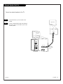
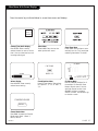
External Speaker Hook Up
Locate the Audio In jack on the back of the
speaker.
Connect a standard audio cable from the Matrix
Out jack on the TV, to the Audio In jack on the
external speaker.
A/V cables
not included
with TV
R- AUDIO- L
VIDEO
IN
MATRIX
OUT
IN
Audio In
Speaker back
ANTENNA
CABLE
M.P.I.
TV back panel
(expanded view)
TV back
1
2
Connect an external speaker to the TV.

PAGE 12
206-3489-O
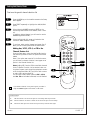
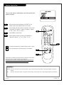
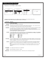
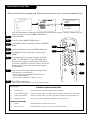
Auto Program (Channel Search)
Use Auto Program to specify Antenna or cable service
incoming signal source and automatically store all of the
channels that are found by channel search
With the Installer remote control in hand, press the
POWER key to turn on the TV.
Press MENU repeatedly so the Setup menu appears.
Using SELECT on the remote control, highlight Auto
Program on the screen.
Press a Right or Left ADJ (Adjust) arrow to reach the
Auto Program screen.
Using SELECT, choose either Cable TV or Off-Air Antenna
on your screen. (The flashing option is selected.)
Press a Right or Left ADJ arrow to begin the Channel
Search.
Press ENTER when finished.
1
2
3
4
5
6
7
TIMER
CHPREVIEW
ENTER
1
2
3
4
5
6
7
8
9
0
POWER
FLSHBK
MUTE
VOL
UME
CHANNEL
TV/FM
CC
MENU
BANK
ADJ
ADJ
SELECT
3/5
Mini glossary
OFF-AIR-ANTENNA If the guest can only view over-the-air broadcasts, select Antenna.
CABLE If you provide cable service to your guests, select Cable.
Note: Auto Program finds channels being received by the TV
tuner.
Cable will not work unless the lodge provides a cable service.
(If the Auto Program line appears in red, then it did not pass
one of the internal tests. To set Auto Program to white, set the
upper nibble of the EEPROM location $1FFh to $B0h.)
4/6
1
7
2

PAGE 13
206-3489-O
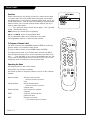
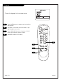
Front Panel Controls
AUDIO
VIDEO
CAPTION
VOL VOL
CH
CH
OFF
ON
IN
LEFT
RIGHT
1
4
Press ON/OFF to turn on your TV.
To access the menus press the MENU button on the
control panel. Cycle through the various menus by
pushing the button repeatedly.
Press the SELECT button repeatedly to highlight the
option you want to modify.
Press either the Right or Left ADJUST button to modi-
fy the option you have chosen.
The menu will disappear after a few seconds.
Using the front control panel to access the menus
1
2
3
4
5
The Front Audio/Video jacks are a direct source con-
nection. If you have a device plugged into the front
Video jack, you will not be able to change channels
until you have unplugged the front Video jack.
2
3
There are three jacks on the front of the TV that make con-
necting Audio/Video devices like camcorders very simple.
To use the front jacks as the signal source, simply plug a
composite video cable into the VIDEO jack. The TV will auto-
matically change its source setting to CAMPORT, as indicated
on the channel selection screen.
Video
Connects the video signals from any piece of
equipment.
Left/Right Audio Used for stereo sound from
various types of equipment.
Typical Front Panel Controls

PAGE 14
206-3488-O
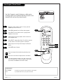
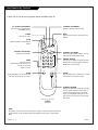
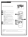
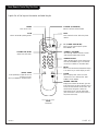
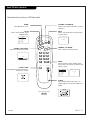
Guest Remote Key Functions
FLASHBK (FLASHBACK)
Returns to the last channel viewed.
POWER
Turns TV On or Off
.
CHANNEL (UP/DOWN)
Scrolls through available channels, and the
Video Channel (Audio/Video source).
MUTE
Turns sound Off and On, while the picture
remains.
ENTER
Press to view the
Channel/Time/Audio display or to
remove any on-screen
display or menu.
NUMBER KEYPAD
Used to key-in numbers and select channels
directly: key-in channel numbers and press
ENTER to go to new channel
.
TIMER
Press repeatedly to set the TV turn-off
time from 10 minutes up to 4-hours.
VOLUME (LEFT/RIGHT)
Adjusts the sound level.
CHANNEL PREVIEW
Displays the available TV channels, including
access to guest’s Parental Control menu (if
Active). Allows guest to select the Video
source. (Use the Audio/Video jacks on the
back of the TV as the source of the picture
and sound.)
CC (CLOSED CAPTIONING)
Direct access to closed captions.
Press ENTER to exit.
A quick list of the keys on the guest remote and what they do
ALARM
Press to display menu, then follow on-screen
instructions to set a wake-up time.
TIMER ALARM
CH PREVIEW
ENTER
1
2
3
4
5
6
7
8
9
0
POWER
FLSHBK
MUTE
VOL
UME
CHANNEL
TV/FM
CC
remote control part number
SC692
124-213-03
TV/FM
Switches between TV and FM radio
modes
.
NOTE:
The channel and volume keys can be used by the guest to select and adjust the Parental
Control settings, if the installer activates the Parental Control option in the Installer
Menu.

206-3489-O
PAGE 15
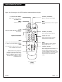
Installer Remote Key Functions
TIMER
CHPREVIEW
ENTER
1
2
3
4
5
6
7
8
9
0
POWER
FLSHBK
MUTE
VOL
UME
CHANNEL
TV/FM
CC
MENU
BANK
ADJ
ADJ
SELECT
FLASHBK (FLASHBACK)
Returns to the last channel viewed.
POWER
Turns TV On or Off
.
CHANNEL (UP/DOWN)
Scrolls through available channels.
MUTE
Turns sound Off and On, while the picture
remains.
ENTER
Press to view the Channel/Time display or
to remove any on-screen display or menu.
NUMBER KEY PAD
Selects channels directly and enters
numeric values for some options
.
remote control part number
LP702
124-213-04
TIMER
Press repeatedly to adjust TV turn-off time
from 10 minutes up to 4-hours.
VOLUME (LEFT/RIGHT)
Adjusts the sound levels.
CC (CLOSED CAPTIONING)
Direct access to closed captions.
Press ENTER to exit.
A quick list of the keys on the LP702 installer’s remote and what they do
BANK
Press and repeat to select a Channel
Memory Bank: Bank 1, 2, 3, or 4.
MENU/SELECT/ADJ (ADJUST)
Adjusts on-screen menus and options.
Press MENU repeatedly to scroll through
menus. Use SELECT to choose an option
and ADJ (adjust) Left/Right to change
the selected option.
CHANNEL PREVIEW
Gives installer access to the guest’s
menus. Displays the available TV channels
and hotel guest’s Parental Control menu
(if active). Selects the Video source. (Use
the Audio/Video jacks on the back of the
TV as the source of the picture and
sound.)
TV/FM
Selects TV or Radio mode on TVs equipped
with FM radio.

PAGE 16
206-3488-O
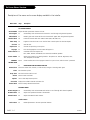
On-Screen Menus Overview
ON-SCREEN MENUS
SETUP MENU Adjusts the basic operational features of the TV
Auto Program 12 Automatically finds and stores active channels to scroll through using Channel Up/Down.
Add/Del/Blnk 17 Manually picks and chooses which active channels will appear when using Channel Up/Down
Channel Labels 18 Labels the channels with their network names (ABC, CBS, HBO, etc.).
Timer Setup 19 Programs a time for the TV to turn itself off after a certain period of time has elapsed.
Clock Set 20 Sets the time.
Caption/Text 21 Chooses the captioning or text option.
Language 22 Picks the language the on-screen menus will appear in.
AUDIO MENU 23 Customizes the sound. Options are:
Bass, Treble, Balance, Audio Mode, Front Surround, SoundRite, Speakers.
VIDEO MENU 24 Adjusts the picture for any viewing situation. The options are: Contrast, Brightness, Color,
Tint, Sharpness, Picture Pref.
PARENTAL 25/44 Allows installer/user to block program content for up to 12 hours, with the use of a password.
CONTROL MENU
27 OTHER MENUS AND ON-SCREEN DISPLAYS
Channel/Time Shows the current time, channel, (or video source) and type of incoming audio signal.
Alarm Sets the wake-up time.
Sleep Timer Sets the time the TV will turn off.
Volume Shows current sound level.
Captions Use to select Caption/Text options.
Ch Preview Displays the available channels and menus list.
Channel Bank Shows currently selected channel bank.
FM RADIO MENUS
FM Auto Program 28 Automatically finds and stores FM radio stations to scroll through with Channel Up/Down.
FM Radio Menus 29 Adjusts the operational features of the FM radio
FM Audio Menu 30 Adjusts the FM radio audio features.
Installer Menus
Service Menu 34 Makes adjustments to the TV’s operational features.
Descriptions of the menus and on-screen displays available to the installer
Menu Name Page Description

PAGE 17
206-3488-A
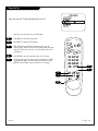
Fine-tune the guest’s channel selection list
Setting Add/Delete/Blank
Press the MENU key on the Installer’s remote so the Setup
menu appears.
Press SELECT repeatedly to highlight the Add/Del/Blnk
option.
Using either the NUMBER keypad and ENTER or the
Channel Up/Down arrows on the remote, select a chan-
nel.
(If adding a deleted channel, you will need to use the
NUMBER keypad and ENTER.)
Using the Right/Left ADJ arrows, pick whether that
channel is Added, Deleted, or Blank.
To continue, select another channel and repeat Step 3.
When you are finished, press ENTER to remove menu.
Adding Aux, VCR 3, VCR 4, or FM to the
Channel Preview List
Go to the Setup menu, select the Add/Del/Blnk option.
Use Channel Up/Down to select the option and choose
Added.
Note: If the option was turned off in the Service menu,
you will have to reinstate it before it can appear as an
option in the Channel Preview list.
Notes: Adding VCR 3 and/or VCR 4 as available channels
forces TV Channel 3 and/or 4 to be retained, when run-
ning Auto Program, even though the equipment connect-
ed to the Antenna/Cable (RF) jack (like a cable convert-
er and/or VCR) may be turned off.
You can elect to Add, Delete or Blank: VCR 3, VCR 4,
and Aux. FM can be Added or Deleted, but not Blanked.
1
2
3
4
5
TIMER
CHPREVIEW
ENTER
1
2
3
4
5
6
7
8
9
0
POWER
FLSHBK
MUTE
VOL
UME
CHANNEL
TV/FM
CC
MENU
BANK
ADJ
ADJ
SELECT
2
CH 44 ADDED
4
3/5
1
If you delete a channel, it isn’t gone for good. Just select it
using the NUMBER keypad on the remote, or add it later.
3
3
Mini glossary
ADD Adds new channels to the list that the guest can scroll through when using the remote.
DELETE Removes channels for one reason or another from the list that the guest can scroll through.
BLANK Removes the video signal from a channel so the guest will only receive the audio signal.

PAGE 18
Channel Labels
CH 47 A & E
Overview
Channel Labels help the user identify the channel or network being viewed.
In the Setup menu with the CH LABELS option highlighted, use the Adjust
Left/Right arrows to scroll through the available channel labels, such as, A &
E, AMC, ESPN, HBO, etc. These are a series of alphabetically organized preset
labels from which you can choose the more common networks. Use any of
these or create custom labels.
- - - - , The 4 dashes will allow a channel label to appear; if one is provided
by XDS. (Extended data service)
NONE, prevents any channel label from appearing.
LAB 1, thru LAB 20, are the 20 programmable labels.
The 20 programmable labels can be customized for your needs.
Each programmable label has 5 characters spaces available.
To Program a Channel Label
First select a channel using the NUMBER keypad and ENTER or the Channel
Up/Down arrows, on the Installer’s remote control.
(To select a deleted channel, use the NUMBER keypad and ENTER.)
To program a channel label, go to the Setup menu and select CH LABELS.
Press the Right/Left adjust arrow to scroll the available preset labels. Scroll
past - - - -, scroll past NONE, to go to the first programmable label slot, LAB
1. Notice that the label appears with the title LAB 1, and is also on a dark
background; which will distinguish it from the preset labels.
Operating the Menu
Use Volume Up/Down to select the first letter.
Press MUTE to clear the label if necessary.
Use Channel Up/Down to change the character to one of the 255 characters
available.
Adjust Left/Right Switches to the next label.
- - moves to the next or previous
label.
Volume Up/Down Selects character spaces
- - moves to the next or previous
character space.
Channel Up/Down Scrolls through the available
characters.
ENTER Accept the channel label and
removes the menu.
MUTE Removes current label,
- - if first character space is selected.
TIMER
CHPREVIEW
ENTER
1
2
3
4
5
6
7
8
9
0
POWER
FLSHBK
MUTE
VOL
UME
CHANNEL
TV/FM
CC
MENU
BANK
ADJ
ADJ
SELECT

PAGE 19
206-3890-O
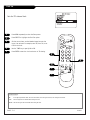
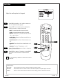
Timer Set Up
1
2
3
4
TIMER
CHPREVIEW
ENTER
1
2
3
4
5
6
7
8
9
0
POWER
FLSHBK
MUTE
VOL
UME
CHANNEL
TV/FM
CC
MENU
BANK
ADJ
ADJ
SELECT
2
TO SET TIMER
3
4
1
5
5
Sets the time the TV will automatically turn off
Be sure to set the Clock first, see next page.
Press MENU to show the Setup menu.
Use SELECT to highlight Timer Setup.
With Timer Setup highlighted as shown above, use the
Left/Right ADJ arrow to pick from the preset times, the time
that the TV will turn itself off, or set the Sleep Timer to Off
to disable it.
Press ENTER to set the timer and return to TV viewing.
The Sleep Timer may be instantly set by pressing the TIMER
key repeatedly. When you have made your selection, press
ENTER to set the Sleep Timer and return to TV viewing.

PAGE 20
206-3489-O
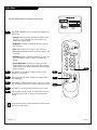
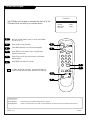
Clock Set
Sets the TV’s internal clock
1
2
3
4
TIMER
CHPREVIEW
ENTER
1
2
3
4
5
6
7
8
9
0
POWER
FLSHBK
MUTE
VOL
UME
CHANNEL
TV/FM
CC
MENU
BANK
ADJ
ADJ
SELECT
11:44 PM
TIMER
1
5
3
4
Press MENU repeatedly to show the Setup menu.
Press SELECT to highlight the Clock Set option.
Set the current time; use the Number keypad to enter the
hours, then minutes. For example, enter 06, then 30, to set
6:30 on the clock.
Use the TIMER key to specify AM or PM.
Press ENTER to start the clock and return to TV viewing.
Mini glossary
TIME A four-digit figure broken down into hours and minutes; first two digits are hours, last two digits are minutes.
HOURS First two digits that are entered when setting the clock.
MINUTES The last two digits that are entered when setting the clock.
5
2
La pagina si sta caricando...
La pagina si sta caricando...
La pagina si sta caricando...
La pagina si sta caricando...
La pagina si sta caricando...
La pagina si sta caricando...
La pagina si sta caricando...
La pagina si sta caricando...
La pagina si sta caricando...
La pagina si sta caricando...
La pagina si sta caricando...
La pagina si sta caricando...
La pagina si sta caricando...
La pagina si sta caricando...
La pagina si sta caricando...
La pagina si sta caricando...
La pagina si sta caricando...
La pagina si sta caricando...
La pagina si sta caricando...
La pagina si sta caricando...
La pagina si sta caricando...
La pagina si sta caricando...
La pagina si sta caricando...
La pagina si sta caricando...
La pagina si sta caricando...
La pagina si sta caricando...
La pagina si sta caricando...
La pagina si sta caricando...
-
 1
1
-
 2
2
-
 3
3
-
 4
4
-
 5
5
-
 6
6
-
 7
7
-
 8
8
-
 9
9
-
 10
10
-
 11
11
-
 12
12
-
 13
13
-
 14
14
-
 15
15
-
 16
16
-
 17
17
-
 18
18
-
 19
19
-
 20
20
-
 21
21
-
 22
22
-
 23
23
-
 24
24
-
 25
25
-
 26
26
-
 27
27
-
 28
28
-
 29
29
-
 30
30
-
 31
31
-
 32
32
-
 33
33
-
 34
34
-
 35
35
-
 36
36
-
 37
37
-
 38
38
-
 39
39
-
 40
40
-
 41
41
-
 42
42
-
 43
43
-
 44
44
-
 45
45
-
 46
46
-
 47
47
-
 48
48


Zenith Concierge H2035DT Installation And Operating Manual, Warranty
- Categoria
- TV LCD
- Tipo
- Installation And Operating Manual, Warranty
- Questo manuale è adatto anche per
in altre lingue
- English: Zenith Concierge H2035DT
Documenti correlati
-
Zenith H25C34Y Installation And Operating Manual, Warranty
-
-
-
-
-
-
-
-
-