
COMFORT TU
TU500, TU800
Gear-motor for sliding gates
Getriebe für Schiebegitter
Motoriduttori per scorrevoli
Motoreducteur pour coulissants
Motorreductores para rejas correderas
Motorredutores para portões de correr
Napęd silnikowy do bram przesuwnych
Motoriduttore interrato
Under grounded gear motor
Motoreducteur enterré
Motorreductor interrado
Unrterflur-Drehtorantrieb
Motorredutor interrado
Podziemny motoreduktor
UNDER
Istruzioni ed avvertenze per l’installazione e l’uso
Instructions and warnings for installation and use
Instrucciones y advertencias para su instalación y uso
Anleitungen und Hinweise zu Installation und Einsatz
Instruções e advertências para a instalação e utilização
Instructions et avertissements pour l’installation et l’usage
Management
System
ISO 9001:2008
www.tuv.com
ID 9105043769

2
EN
INDEX
1
2
3
7
4
5
6
Safety warnings
2.1
2.2
4.1
4.2
4.3
4.4
4.5
5.1
5.2
Product overview
Product description
Set panel and technical characteristics
Preliminary checks
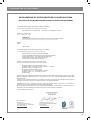
EC Declaration of Conformity
Installing the product
Installing
Fixing
Rack assembling
Limit switch xing
Manual running
Testing and commissioning
Testing
Commissioning
Figures
pag. 3
pag. 4
pag. 4
pag. 4
pag. 5
pag. 39
pag. 5
pag. 5
pag. 6
pag. 6
pag. 6
pag. 6
pag. 6
pag. 6
pag. 6
pag. 37

3
EN
1 - SAFETY WARNINGS
ORIGINAL INSTRUCTIONS - important safety instructions. Fol-
low the instructions since incorrect installation can lead to se-
vere inquiry! Save these instructions.
Read the instructions carefully before proceeding with installation.
The design and manufacture of the devices making up the
product and the information in this manual are compliant with
current safety standards. However, incorrect installation or
programming may cause serious injury to those working on or
using the system. Compliance with the instructions provided
here when installing the product is therefore extremely impor-
tant.
If in any doubt regarding installation, do not proceed and contact the
Marantec Technical Service for clarications.
Under European legislation, an automatic door or gate system
must comply with the standards envisaged in the Directive
2006/42/EC (Machinery Directive) and in particular standards
EN 12453; EN 12635 and EN 13241-1, which enable declaration
of presumed conformity of the automation system.
Therefore, nal connection of the automation system to the electri-
cal mains, system testing, commissioning and routine maintenance
must be performed by skilled, qualied personnel, in observance of
the instructions in the “Testing and commissioning the automation
system” section.
The aforesaid personnel are also responsible for the tests required
to verify the solutions adopted according to the risks present, and for
ensuring observance of all legal provisions, standards and regula-
tions, with particular reference to all requirements of the EN 12453
standard which establishes the test methods for testing door and
gate automation systems.
Before starting installation, perform the following checks and
assessments:
ensure that every device used to set up the automation system is
suited to the intended system overall. For this purpose, pay special
attention to the data provided in the “Technical specications” sec-
tion. Do not proceed with installation if any one of these devices is
not suitable for its intended purpose;
check that the devices purchased are sucient to guarantee system
safety and functionality;
perform a risk assessment, including a list of the essential safety
requirements as envisaged in Annex I of the Machinery Directive,
specifying the solutions adopted. The risk assessment is one of the
documents included in the automation system’s technical le. This
must be compiled by a professional installer.
Considering the risk situations that may arise during instal-
lation phases and use of the product, the automation system
must be installed in compliance with the following safety pre-
cautions:
never make modications to any part of the automation system other
than those specied in this manual. Operations of this type can only
lead to malfunctions. The manufacturer declines all liability for da-
mage caused by unauthorised modications to products;
if the power cable is damaged, it must be replaced by the manufac-
turer or its after-sales service, or in all cases by a person with similar
qualications, to prevent all risks;
do not allow parts of the automation system to be immersed in water
or other liquids. During installation ensure that no liquids are able to
enter the various devices;
should this occur, disconnect the power supply immediately and
contact a Marantec Service Centre. Use of the automation system in
these conditions may cause hazards;
never place automation system components near to sources of heat
or expose them to naked lights. This may damage system compo-
nents and cause malfunctions, re or hazards;
The drive shall be disconnected from its power source during
cleaning, maintenance and when replacing parts. If the discon-
nect device is not in a visible location, ax a notice stating:
“MAINTENANCE IN PROGRESS”:
connect all devices to an electric power line equipped with an
earthing system;
the product cannot be considered to provide eective protection
against intrusion. If eective protection is required, the automation
system must be combined with other devices;
the product may not be used until the automation system “commis-
sioning” procedure has been performed as specied in the “Automa-
tion system testing and commissioning” section;
the system power supply line must include a circuit breaker device
with a contact gap allowing complete disconnection in the conditions
specied by class III overvoltage;
use unions with IP55 or higher protection when connecting hoses,
pipes or cable glands;
the electrical system upstream of the automation system must com-
ply with the relevant regulations and be constructed to good wor-
kmanship standards;
this appliance can be used by children aged from 8 years and above
and persons with reduced physical, sensory or mental capabilities or
lack of experience and knowledge if they have been given supervi-
sion or instruction concerning use of the appliance in a safe way and
understand the hazards involved;
before starting the automation system, ensure that there is no-one
in the immediate vicinity;
before proceeding with any cleaning or maintenance work on the
automation system, disconnect it from the electrical mains;
special care must be taken to avoid crushing between the part ope-
rated by the automation system and any xed parts around it;
children must be supervised to ensure that they do not play with the
equipment.
that the drive cannot be used with a driven part incorporating a wi-
cket door unless the drive can only be operated with the wicket door
in the safe position;
The automation system component packaging material must
be disposed of in full observance of current local waste dispo-
sal legislation.
Marantec reserves the right to amend these instructions if ne-
cessary; they and/or any more recent versions are available at
www.marantec.com
Frequently examine the installation for imbalance where ap-
plicable and signs of wear or damage to cables, springs and
mounting.
Do not use if repair or adjustment is necessary.
ATTENTION !
ATTENTION !
ATTENTION !
ATTENTION !
ATTENTION !

4
EN
2.1 - Product description
2 - INTRODUCING THE PRODUCT
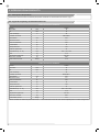
2.2 - Set panel and and technical characteristics
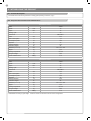
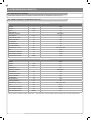
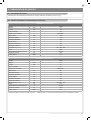
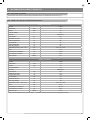
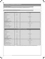
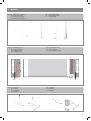
Irreversible electromechanical gearmotor for sliding gates operating at 230 Vac. (Fig.1)
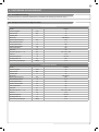
TECHNICAL DATA
Model TU500
Speed* cm/s 16
Torque Nm 16
Working cycle % 30
Control unit CBX102B **
Power Vac 230
Motor consumption A 1,3
Consumption power W 300
Capacitor µF 12
Thermoprotection °C 150
Protection degree IP 44
dimension (L - P- H) mm 320 - 184 - 260
Weight kg 12,5
Working temperature °C -20 +55
Max gate weight kg 500
Sound emission level dB(A) ≤ 70
TECHNICAL DATA
Model TU800
Speed* cm/s 16
Torque Nm 29
Working cycle % 30
Control unit CBX102B **
Power Vac 230
Motor consumption A 1,9
Consumption power W 450
Capacitor µF 16
Thermoprotection °C 150
Protection degree IP 44
dimension (L - P- H) mm 320 - 184 - 260
Weight kg 12,5
Working temperature °C -20 +55
Max gate weight kg 800
Sound emission level dB(A) ≤ 70
* Variable data according to gate weight. **Refer to control unit instructions for the correct conguration.

5
EN
4 - INSTALLING THE PRODUCT
3 - PRELIMINARY CHECKS
Before installing this product, verify and check the following steps:
- Check that the gate or door are suitable for automation
- The weight and size of the gate be within the maximum permissible
operating limits specied in Paraghaph 2.2
- Check the presence and strength of the security mechanical stops
of the gate
- Check that the mounting area of the product is not subject to ood-
ing
- Conditions of high acidity or salinity or proximity to heat sources
could cause malfunction of the product
- Extreme weather conditions (for example the presence of snow,
ice, high temperature range, high temperatures) may increase the
friction and therefore the force required for the handling and initial
starting point may be higher than under normal conditions.
- Check that the manual operation of gate is smooth and friction-free
and there is no risk of derailment of the same
- Check that the gate is in mechanical equilibrium and stationary if
left in any position
- Check that the power line to supply the product is equipped with
proper grounding safety and protected by a magnetothermal and dif-
ferential security device
- Provide the power system with a disconnecting device with a gap
of contacts enabling full disconnection under the conditions dictated
by the overvoltage category III.
- Ensure that all materials used for the installation comply with cur-
rent regulations
4.1 - Installation
The automation system must be equipped with a pressure-sen-
sitive edge protecting all possible crushing points (hands, feet,
etc.) in accordance with the requirements of the EN 13241-1
standard.
The gate has to be equipped with stop locks at the opening and
closing, which prevent the gate derailment.
The installer must verify that the working temperature range
stated on the automation device is suitable for the location
where it is installed.
ATTENTION !
ATTENTION !
ATTENTION !
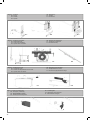
Respecting the overall size, x to ground the base-plate through
4 sturdy screw-anchors (g.3) or drown it into the concrete (g.3).
Plan for one or more sheathing for the passage of the power lines.
N.B. The exact dimensions of the rack must be known to allow pre-
cise calculation of the counterplate position.
Fig.2 is an example of a typical system:
Post for photocells (1)
Automation electromechanical (2)
Photocell detectors (3)
Flashing light (4)
Key switch (5)
Radio transmitter (6)
Pressure-sensitive edge (7)

EN
6
Take the lid o unscrewing the screws (g.4.1). Put the gearmotor
on the plate. Insert the two socket head screws (g.4.2).
It is important to lock the two socket head screws forcefully, making
sure, that the gearmotor is rmly on the ground, during the whole
movement/operation of the gate.
If the regulating allowed by the rack is not sucient, it is possible to
counterbalance the gearmotor high working on the four screws
(g.4.3).
The screws should be tightened again after the motor has been
operated a few times.
4.2 - Fixing
4.3 - Rack assembling
Release the gearmotor as indicated by the g.7 and open entirely
the gate.
Put a rack element on the pinion gear and fasten it to the gate with
screw and spacing bars.
Move the gate manually bringing the pinion gear into line with the
last spacing bar.
Fasten the rack element for good.
For a correct positioning of the other elements and to assure their
straightness, it is necessary to employ a rack element using it as
support and reference (g.5.2).
It is besides necessary to assure an aperture of 2 mm between
rack and pinion gear, so that the gate weight doesn’t rest on the
gearmotor pinion gear (g.5.1).
4.4 - Limit switch xing
The gate has to be equipped with stop locks at the opening and
closing, which prevent the gate derailment.
The stop lock position must assure that the limit switch brackets
don’t collide with the pinion gear.
Haul the gate manually at the opening leaving, depending on the
gate weight, a crack from 30 to 50 mm between the main gate and
mechanical stop.
Fasten the limit switch bracket through the dowels (g.6.2) so that
the limit switch is pressed (g.6.1).
Repeat the operation with the main gate at the closing.
4.5 - Manual running
Insert the key and turn it 90° in anticlockwise direction. (Fig.7)
Pull the knob till it is perpendicular to the gearmotor.
N.B. Take care to re-engage the gearmotor before starting it up.
Engaging with the motor running may damage its internal com-
ponents.
5 - TESTING AND COMMISSIONING THE AUTOMATION SYSTEM
5.2 - Commissioning
Once all (and not just some) of the system devices have passed the
testing procedure, the system can be commissioned;
the system’s technical dossier must be produced and kept for
10 years. It must contain the electrical wiring diagram, a drawing
or photograph of the system, the analysis of the risks and the
solutions adopted to deal with them, the manufacturer’s declaration of
conformity for all connected devices, the operator’s manual for
every device and the system maintenance plan;
x a dataplate with the details of the automation, the name of
the person who commissioned it, the serial number and year of
construction and the CE marking on the gate or door;
also t a sign specifying the procedure for releasing the system by
hand;
draw up the declaration of conformity, the instructions and
precautions for use for the end user and the system maintenance
plan and consign them to the end user;
ensure that the user has fully understood how to operate the system
in automatic, manual and emergency modes;
the end user must also be informed in writing about any risks and
hazards still present;
After detecting an obstacle, the gate or door stops
during its opening travel and automatic closure is disabled; to
restart operation, the user must press the control button or use
the transmitter.
5.1 - Testing
All system components must be tested following the procedures
described in their respective operator’s manuals;
ensure that the recommendations in Chapter 1 - Safety Warnings -
have been complied with;
check that the gate or door is able to move freely once the automation
system has been released and is well balanced, meaning that it will
remain stationery when released in any position;
check that all connected devices (photocells, sensitive edges,
emergency buttons, etc.) are operating correctly by performing gate
or door opening, closing and stop tests using the connected control
devices (transmitters, buttons or switches);
perform the impact measurements as required by the EN 12453
standard, adjusting the control unit’s speed, motor force and
deceleration functions if the measurements do not give the required
results, until the correct setting is obtained.
The system must be tested by a qualied technician, who must
perform the tests required by the relevant standards in relation
to the risks present, to check that the installation complies with
the relevant regulatory requirements, especially the EN 12453
standard which species the test methods for gate and door automation
systems.

7
DE
INHALTSVERZEICHNIS
1
2
3
4
5
6
7
Sicherheitshinweise
2.1
2.2
4.1
4.2
4.3
4.4
4.5
5.1
5.2
Einführung in das Produkt
Produktbeschreibung
Bauplan und technische Eigenschaften
Vorabkontrollen
Produktinstallation
Installation
Befestigung
Montage der zahnstange
Befestigung der anschläge
Handbetrieb
Test und Inbetriebnahme
Abnahme
Inbetriebnahme
Abbildungen
EG-Konformitätserklärung
S. 8
S. 9
S. 9
S. 9
S. 10
S. 10
S. 10
S. 11
S. 11
S. 11
S. 11
S. 11
S. 11
S. 11
S. 37
S. 39

8
DE
1 - SICHERHEITSHINWEISE
ORIGINALANWEISUNGEN – Wichtige Sicherheitsanweisun-
gen. Für die Sicherheit der Personen ist es wichtig, die folgen-
den Sicherheitsanweisungen zu befolgen. Bewahren Sie diese
Anweisungen auf.
Vor Durchführung der Installation lesen Sie die Anleitung bitte
aufmerksam durch.
Die Konstruktion und die Herstellung der Geräte, aus denen
sich das Produkt zusammensetzt, und die in diesem Handbuch
enthaltenen Informationen entsprechen den geltenden Si-
cherheitsvorschriften. Dennoch können eine falsche Installa-
tion und eine falsche Programmierung schwerwiegende Ver-
letzungen bei Personen verursachen, die die Arbeit ausführen,
und bei denen, die die Anlage benutzen werden. Aus diesem
Grund ist es wichtig, während der Installation strikt alle Anwei-
sungen in diesem Handbuch zu beachten.
Bei Zweifel jeglicher Art die Installation abbrechen und ggf. den Ma-
rantec Kundendienst zur Klärung kontaktieren.
Für die europäische Gesetzgebung muss der Einbau einer au-
tomatischen Tür oder eines automatischen Tors den Bestim-
mungen der Richtlinie 2006/42/EG (Maschinenrichtlinie) und im
Besonderen den Normen EN 12453, EN 12635 und EN 13241-1
entsprechen, die eine Konformitätserklärung der Automatisie-
rung ermöglichen.
In Anbetracht dessen müssen die endgültige Verbindung der Auto-
matisierung ans Stromnetz, die Endabnahme der Anlage, die Inbe-
triebnahme und die regelmäßige Wartung von qualiziertem und
erfahrenem Personal entsprechend den Anleitungen unter „Prüfung
und Inbetriebnahme der Automatisierung“ durchgeführt werden.
Außerdem muss das Personal auch die vorgesehenen Tests nach
den vorhandenen Risiken festlegen und die Einhaltung der Gesetze,
Vorschriften und Regeln überprüfen: insbesondere die Einhaltung
der Norm EN 12453, welche die Prüfverfahren für die Automatisie-
rung von Türen und Toren festlegt.
Vor Installationsbeginn folgende Analysen und Prüfungen dur-
chführen:
Sicherstellen, dass die für die Automatisierung vorgesehenen
Vorrichtungen für die zu realisierende Anlage geeignet sind. Die-
sbezüglich aufmerksam die im Kapitel „Technische Eigenschaften“
aufgeführten Daten prüfen. Die Installation nicht durchführen, wenn
auch nur eine der Vorrichtungen nicht für den Gebrauch geeignet ist.
Sicherstellen, dass die erworbenen Vorrichtungen ausreichend sind,
um die Sicherheit und Funktion der Anlage zu gewährleisten.
Die Risikoanalyse durchführen, welche auch die Liste der Si-
cherheitsanforderungen, aufgeführt in Anhang I der Maschinenricht-
linie, beinhalten muss, und die angewandten Lösungen nennen.Die
Risikoanalyse ist eine der Unterlagen, aus denen sich die techni-
schen Unterlagen der Automatisierung zusammensetzen. Diese
müssen von einem erfahrenen Installateur ausgefüllt werden.
In Anbetracht der Gefahrensituationen, die bei Installation und
Benutzung des Produktes auftreten können, muss die Automa-
tisierung unter Berücksichtigung folgender Hinweise installiert
werden:
Keine Änderungen an der Automatisierung vornehmen, wenn diese
nicht in diesem Handbuch vorgesehen sind. Diese können nur zu
Funktionsstörungen führen. Der Hersteller übernimmt keine Haftung
für Schäden, die durch eigenmächtige Änderungen am Produkt ve-
rursacht wurden.
Ist das Stromkabel beschädigt, muss es vom Hersteller, seinem
technischen Kundendienst oder einer ähnlich qualizierten Person
ersetzt werden, um Gefährdungen zu vermeiden;
Die einzelnen Komponenten der Automatisierung dürfen nicht in
Wasser oder andere Flüssigkeiten getaucht werden. Bei der In-
stallation darauf achten, dass keine Flüssigkeit ins Innere der Vor-
richtungen dringt.
Sollten Flüssigkeiten ins Innere der Automatisierungskomponenten
dringen, sofort die Stromzufuhr abschalten und sich an den Maran-
tec Kundendienst wenden. Die Benutzung der Automatisierung in
derartigen Situationen kann gefährlich sein.
Die einzelnen Komponenten weder Wärmequellen noch oenen
Flammen aussetzen. Dadurch können Schäden, Störungen und
Gefahrensituationen entstehen oder ein Brand ausbrechen
Die Einheit ist während der Reinigung, Wartung und Auswe-
chslung von Bestandteilen von der Speisung abzutrennen.
Sollte die Abschaltvorrichtung nicht sichtbar sein, ein Schild
mit der Aufschrift „IN WARTUNG“ anbringen.
Alle Vorrichtungen müssen mit einer Stromleitung verbunden wer-
den, die sicher geerdet ist.
Dieses Produkt kann nicht als ausreichendes System für den
Einbruchsschutz angesehen werden. Wenn Sie sich ausreichend
schützen wollen, müssen andere Vorrichtungen in die Automatisie-
rung integriert werden.
Wie im Absatz „Prüfung und Inbetriebnahme der Automatisierung“
vorgesehen, darf das Produkt erst nach der „Inbetriebnahme“ der
Automatisierung benutzt werden.
Im Stromnetz der Anlage eine Abschaltvorrichtung mit ausreichen-
dem Önungsabstand der Kontakte vorsehen, die, wie von der
Überspannungskategorie III gefordert, die komplette Abschaltung
erlaubt.
Verwenden Sie für die Verbindung von steifen und exiblen Rohren
oder Kabeldurchgängen Anschlüsse mit dem Schutzgrad IP55 oder
höher.
Die elektrische Anlage vor der Automatisierung muss den geltenden
Bestimmungen entsprechen und fachgerecht ausgeführt sein.
Das Gerät kann von Kindern im Alter von nicht weniger als 8 Jahren
und von Personen mit beschränkten körperlichen, sensoriellen und
geistigen Fähigkeiten oder ohne Erfahrung bzw. ohne das notwen-
dige Bewußtsein verwendet werden, vorausgesetzt, dass sie dabei
überwacht werden oder dass sie Anweisungen über den sicheren
Gebrauch des Gerätes und das Verständnis der damit verbundenen
Gefahren erhalten haben;
Vergewissern Sie sich vor der Inbetriebsetzung der Automatisie-
rung, dass sich keine Personen in unmittelbarer Nähe benden;
Vor jeder Reinigung und Wartung ist die Automatisierung vom
Stromnetz zu trennen;
Besondere Vorsicht ist geboten, um Quetschungen zwischen dem
geführten Teil und festen Elementen in der unmittelbaren Nähe zu
vermeiden;
Kinder sollten beaufsichtigt werden, um sicherzustellen, dass sie
nicht mit dem Gerät spielen.
Das Gerät darf mit einer automatisierten Tür mit eingebauter Fuß-
gängertür nicht verwendet werden.
ACHTUNG !
ACHTUNG !
ACHTUNG !
ACHTUNG !
ACHTUNG !
Die Anlage ist regelmäßig dahingehend zu prüfen, dass keine
Unwucht und Zeichen einer mechanischen Abnutzung, sowie
beschädigte Kabel, Federn und Stützelemente vorhanden sind.
Verwenden Sie nicht, wenn eine Reparatur oder Einstellung er-
forderlich ist.
Das Verpackungsmaterial aller Automatisierungskomponenten
muss entsprechend den örtlichen Bestimmungen entsorgt wer-
den.
Marantec behält sich vor, diese Anweisungen notfalls zu ändern;
diese Anweisungen und/oder eine neuere Version benden sich auf
der Website www.marantec.com

9
DE
2.1 - Produktbeschreibung
2 - EINFÜHRUNG IN DAS PRODUKT
2.2 - Bauplan und technische Eigenschaften
Elektromechanischer irreversibler Getriebemotor für Schiebetore für Versorgung mit 230 Vac. (Fig.1)
* Wert je nach Torgewicht variabel. ** Konsultieren Sie die Anleitungen des Steuerung für die richtige Konguration.
TECHNISCHE DATEN
Modell TU500
Geschwindigkeit* cm/s 16
Drehmoment Nm 16
Arbeitszyklus % 30
Steuerung CBX102B **
Spannungsversorgung Vac 230
Motorstromaufnahme A 1,3
Leistungsaufnahme W 300
Schalten kondensator µF 12
Thermoprotektion °C 150
Schutzart IP 44
Abmessungen (B - T - H) mm 320 - 184 - 260
Gewicht kg 12,5
Betriebstemperatur °C -20 +55
Höchstgewicht Tor kg 500
Aussendung Schallpegel dB(A) ≤ 70
TECHNISCHE DATEN
Modell TU800
Geschwindigkeit* cm/s 16
Drehmoment Nm 29
Arbeitszyklus % 30
Steuerung CBX102B **
Spannungsversorgung Vac 230
Motorstromaufnahme A 1,9
Leistungsaufnahme W 450
Schalten kondensator µF 16
Thermoprotektion °C 150
Schutzart IP 44
Abmessungen (B - T - H) mm 320 - 184 - 260
Gewicht kg 12,5
Betriebstemperatur °C -20 +55
Höchstgewicht Tor kg 800
Aussendung Schallpegel dB(A) ≤ 70

10
DE
DE
4.1 - Installation
4 - PRODUKTINSTALLATION
3 - VORABKONTROLLEN
Vor der Installation bitte folgende Punkte prüfen und kontrollieren:
- Kontrollieren ob sich Tor oder Tür für die Automatisierung eignen.
- Gewicht und Größe des Tors müssen innerhalb der maximal zu-
lässigen Einsatzgrenzen liegen, die in Abb. 2 angegeben sind.
- Kontrolle des Vorhandenseins und der Stärke der mechanischen
Sicherheitsanschläge des Tors.
- Sicherstellen, dass der Befestigungsbereich nicht überutet wer-
den kann.
- Überhöhter Säure- oder Salzgehalt oder die Nähe von Wärme-
quellen können Fehlfunktion des Produktes verursachen.
- bei extremen klimatischen Verhältnissen (wie z.B. Schnee, Eis,
hohe Temperaturunterschiede, hohe Temperaturen) könnten sich
die Reibungen verstärken, deshalb könnte der Kraftaufwand für
die Bewegung und das Anlaufmoment höher sein als im Normal-
zustand.
- Kontrollieren, dass die manuelle Bewegung des Tors üssig und
ohne Reibungspunkte ist und keine Entgleisungsgefahr besteht.
- Prüfen, dass sich das Tor im Gleichgewicht bendet und folglich in
jeder Stellung stillsteht.
- Prüfen, dass die Stromleitung für den Anschluss des Produkts über
eine gesicherte Erdung verfügt und mit einem Leitungsschutz- und
Dierentialschalter geschützt ist.
– Im Stromnetz der Anlage eine Abschaltvorrichtung mit ausreichen-
der Önungsweite der Kontakte vorsehen, die, wie von der Über-
spannungskategorie III gefordert, die komplette Abschaltung erlaubt.
- Sicherstellen, dass das gesamte benutzte Material den geltenden
Normen entspricht.
Der Antrieb muss zum Schutze vor allen möglichen Quetsch-
stellen (für Hände, Füße...) notwendigerweise mit einer Si-
cherheitsleiste im Sinne der Bestimmungen der Norm EN
13241-1 ausgestattet sein.
Der Installateur muss prüfen, dass der auf dem Antrieb ange-
gebene Temperaturbereich für die Position, an der er installiert
werden muss, geeignet ist.
ACHTUNG !
ACHTUNG !
ACHTUNG !
Das Tor muss mit Anschlägen zur Begrenzung der Önungs-
und Schließbewegung ausgestattet sein, um ein Entgleisen zu
verhindern.
Unter Berücksichtigung der Einbaumaße die Bodenplatte mit vier
robusten Spreizdübeln am Boden befestigen (g.3) oder in Beton
einlassen (g.3). Eine oder mehrere Hüllen für die Verlegung der
Stromkabel installieren.
NB: Die Abmaße der Zahnstange müssen bekannt sein, um die
Position der Gegenplatte genau berechnen zu können.
Abb. 2 zeigt ein typisches Installationsbeispiel:
Standsäule mit Fotozelle (1)
Antriebsautomatisierung (2)
Fotozelle zur Erfassung (3)
Signal-Blinkleuchte (4)
Schlüsseltaster (5)
Funksender (6)
Druckempndliche Kante (7)

11
DE
4.5 - Handbetrieb
Den Schlüssel einstecken und um 90° drehen. (Fig.7)
Den Gri so weit zum Körper hinziehen, dass er senkrecht zum An-
trieb steht.
Wichtig: Den Getriebemotor zuerst wieder blockieren, bevor
er betätigt wird. Wenn bei laufendem Motor angekuppelt wird,
könnten Innenelemente beschädigt werden.
4.4 - Befestigung der anschläge
Das Tor muss mit Anschlägen zur Begrenzung der Önungs- und
Schließbewegung ausgestattet sein, um ein Entgleisen zu
verhindern.
Die Position des Anschlags ist so zu wählen, dass die Anschlagbügel
keinesfalls gegen den Ritzel stoßen.
Das Tor von Hand in Önungsstellung bringen und - je nach
seinem Gewicht - einen Freiraum von 30 bis 50 mm zwischen Tor und
Anschlag belassen.
Den Anschlagbügel mit Stiften befestigen (g.6.1), so dass der
Mikro-Endschalter gedrückt wird (g.6.2).
Diesen Vorgang auch bei geschlossenem Tor ausführen.
5 - TEST UND INBETRIEBNAHME DER AUTOMATION
5.2 - Inbetriebnahme
Nach positivem Test aller (und nicht nur einiger) Vorrichtungen der
Anlage kann die Inbetriebnahme vorgenommen werden;
die technischen Unterlagen der Anlage müssen ausgestellt und 10
Jahre lang aufbewahrt werden; sie umfassen den Schaltplan, die
Zeichnung oder ein Foto der Anlage, die Risikoanalyse und die
jeweiligen Lösungen, die Konformitätserklärung des Her-
stellers bezüglich aller angeschlossenen Vorrichtungen, die
Gebrauchsanleitungen aller Geräte und den Wartungsplan der Anlage;
am Tor oder an der Tür ein Schild mit den Daten der
Automation, dem Namen des Verantwortlichen der Inbetriebnahme,
der Seriennummer, dem Herstellungsjahr sowie dem CE-Zeichen
anbringen;
ein Schild mit den notwendigen Handlungen zur manuellen
Entriegelung der Anlage anbringen;
die Konformitätserklärung ausfüllen und dem Endbenutzer
zusammen mit der Gebrauchsanweisung und dem Wartungsplan
der Anlage aushändigen;
sicherstellen, dass der Benutzer den automatischen und manuellen
Betrieb und die Notausschaltung der Automation verstanden hat;
den Endbenutzer auch schriftlich über Gefahren und Risiken
informieren;
Nach Erkennen eines Hindernisses hält das Tor oder die Tür
während der Önung an und die automatische Schließung wird
ausgeschlossen. Um die Bewegung fortzusetzen, muss man
die Bedientaste drücken oder den Sender benutzen.
5.1 - Abnahme
Alle Komponenten der Anlage müssen gemäß den jeweiligen
Anweisungen der Handbücher endgeprüft werden;
kontrollieren, dass die Anweisungen des Kapitels 1 – Anweisungen
zur Sicherheit beachtet werden;
kontrollieren, dass sich das Tor oder die Tür nach der Entriegelung
der Automation frei bewegen können und sich in jeder Stellung im
Gleichgewicht benden und stillstehen;
die korrekte Funktion aller verbundenen Vorrichtungen (Fotozellen,
Schaltleisten, Notschalter und anderes) kontrollieren, indem man
mit den angeschlossenen Steuervorrichtungen (Sender, Tasten,
Wahlschalter) alle Proben der Önung, Schließung und Blockierung
des Tors oder der Tür durchführt;
die Messungen der Aufprallkraft nach EN 12453 durchführen,
dabei Geschwindigkeit, Motorkraft und Verlangsamungen des
Steuergeräts einstellen, falls die Messungen nicht die gewünschten
Werte zeigen.
Die Endabnahme der Anlage muss von einem qualizierten
Techniker durchgeführt werden, der die durch die einschlägigen
Bestimmungen je nach bestehenden Gefahren vorgesehenen
Prüfungen ausführt und die Einhaltung der Anforderungen prüft.
Besonders zu berücksichtigen ist hierbei die Norm EN 12453, wel-
che die Prüfverfahren für Automationen an Türen und Toren festlegt.
4.3 - Montage der zahnstange
Die Schrauben abdrehen und die Abdeckung abnehmen (g.4.1).
Den Torantrieb auf die Platte auegen. Die zwei Inbusschrauben
eindrehen (g.4.2).
Es ist wichtig, dass die Inbusschrauben sehr fest angezogen
werden, damit der Antrieb entlang der gesamten 90 mm Torbewe-
Den Torantrieb entriegeln (g.7) und das Tor gänzlich önen.
Ein Zahnstangenelement am Ritzel aufstützen und dieses mit
Schrauben und Distanzstücken am Tor befestigen.
Das Tor von Hand bewegen, bis sich der Ritzel auf der Höhe des
letzten Distanzstücks bendet.
Das Zahnstangenelement endgültig arretieren.
gung fest am Boden verankert ist.
Falls die Einstellung der Zahnstange nicht ausreicht, kann die Höhe
des Antriebs anhand der vier Schrauben reguliert werden (g.4.3).
Es wird empfohlen, die Schrauben nach einigen Motorbewegungen
nachzuziehen.
Zur Gewährleistung der korrekten Positionierung und Geradlinigkeit
der restlichen Elemente muss ein Element nur als Auage und Bezug
eingesetzt werden (g.5.2).
Überdies muss zwischen Zahnstange und Ritzel ein Spiel von 2 mm
verbleiben, damit das Gewicht des Tores nicht auf dem Ritzel des
Torantriebs lastet (g.5.1).
4.2 - Befestigung

12
IT
7
Dichiarazione CE di conformità pag. 39
7
pag. 37
INDICE
1
2
3
4
5
6
Avvertenze per la sicurezza
2.1
2.2
4.1
4.2
4.3
4.4
4.5
5.1
5.2
Introduzione al prodotto
Descrizione del prodotto
Quadro d’insieme e caratteristiche tecniche
Veriche preliminari
Installazione del prodotto
Installazione
Fissaggio
Fissaggio cremagliera
Fissaggio necorsa
Funzionamento manuale
Collaudo e messa in servizio
Collaudo
Messa in servizio
Immagini
pag. 13
pag. 14
pag. 14
pag. 14
pag. 15
pag. 15
pag. 15
pag. 16
pag. 16
pag. 16
pag. 16
pag. 16
pag. 16
pag. 16

13
IT
1 - AVVERTENZE PER LA SICUREZZA
ISTRUZIONI ORIGINALI – importanti istruzioni di sicurezza. Se-
guire tutte le istruzioni perchè una scorretta installazione può porta-
re a lesioni gravi! Conservare queste istruzioni.
Leggere attentamente le istruzioni prima di eseguire l’installazione.
La progettazione e la fabbricazione dei dispositivi che com-
pongono il prodotto e le informazioni contenute nel presente
manuale rispettano le normative vigenti sulla sicurezza. Ciò
nonostante un’installazione e una programmazione errata pos-
sono causare gravi ferite alle persone che eseguono il lavoro
e a quelle che useranno l’impianto. Per questo motivo, durante
l’installazione, è importante seguire attentamente tutte le istru-
zioni riportate in questo manuale.
Non procedere con l’installazione se si hanno dubbi di qualunque
natura e richiedere eventuali chiarimenti al Servizio Assistenza Ma-
rantec.
Per la legislazione Europea la realizzazione di una porta au-
tomatica o un cancello automatico deve rispettare le norme
previste dalla Direttiva 2006/42/CE (Direttiva Macchine) e in
particolare, le norme EN 12453; EN 12635 e EN 13241-1, che
consentono di dichiarare la conformità dell’automazione.
In considerazione di ciò, il collegamento denitivo dell’automatismo
alla rete elettrica, il collaudo dell’impianto, la sua messa in servizio
e la manutenzione periodica devono essere eseguiti da personale
qualicato ed esperto, rispettando le istruzioni riportate nel riquadro
“Collaudo e messa in servizio dell’automazione”.
Inoltre, egli dovrà farsi carico di stabilire anche le prove previste in
funzione dei rischi presenti e dovrà vericare il rispetto di quanto
previsto da leggi, normative e regolamenti: in particolare, il rispetto
di tutti i requisiti della norma EN 12453 che stabilisce i metodi di
prova per la verica degli automatismi per porte e cancelli.
Prima di iniziare l’installazione, eettuare le seguenti analisi e
veriche:
vericare che i singoli dispositivi destinati all’automazione siano
adatti all’impianto da realizzare. Al riguardo, controllare con partico-
lare attenzione i dati riportati nel capitolo “Caratteristiche tecniche”.
Non eettuare l’installazione se anche uno solo di questi dispositivi
non è adatto all’uso;
vericare se i dispositivi acquistati sono sucienti a garantire la si-
curezza dell’impianto e la sua funzionalità;
eseguire l’analisi dei rischi che deve comprendere anche l’elenco dei
requisiti essenziali di sicurezza riportati nell’Allegato I della Direttiva
Macchine, indicando le soluzioni adottate. L’analisi dei rischi è uno
dei documenti che costituiscono il fascicolo tecnico dell’automazio-
ne. Questo dev’essere compilato da un installatore professionista.
Considerando le situazioni di rischio che possono vericarsi
durante le fasi di installazione e di uso del prodotto è necessa-
rio installare l’automazione osservando le seguenti avvertenze:
non eseguire modiche su nessuna parte dell’automatismo se non
quelle previste nel presente manuale. Operazioni di questo tipo
possono solo causare malfunzionamenti. Il costruttore declina ogni
responsabilità per danni derivanti da prodotti modicati arbitraria-
mente;
evitare che le parti dei componenti dell’automazione possano venire
immerse in acqua o in altre sostanze liquide. Durante l’installazio-
ne evitare che i liquidi possano penetrare all’interno dei dispositivi
presenti;
se il cavo di alimentazione risulta danneggiato esso deve essere
sostituito dal costruttore o dal suo servizio di assistenza tecnica o
comunque da una persona con qualica similare in modo da preve-
nire ogni rischio;
se sostanze liquide penetrano all’interno delle parti dei componenti
dell’automazione, scollegare immediatamente l’alimentazione elet-
trica e rivolgersi al Servizio Assistenza Marantec. L’utilizzo dell’auto-
mazione in tali condizioni può causare situazioni di pericolo;
non mettere i vari componenti dell’automazione vicino a fonti di ca-
lore né esporli a amme libere. Tali azioni possono danneggiarli ed
essere causa di malfunzionamenti, incendio o situazioni di pericolo;
L’unità deve essere scollegata dalla fonte di alimentazione du-
rante la pulizia, la manutenzione e la sostituzione di componen-
ti. Se il dispositivo di sconnessione non è a vista, apporre un
cartello con la seguente dicitura: “MANUTENZIONE IN
CORSO”;
tutti i dispositivi devono essere collegati ad una linea di alimentazio-
ne elettrica dotata di messa a terra di sicurezza;
il prodotto non può essere considerato un ecace sistema di prote-
zione contro l’intrusione. Se desiderate proteggervi ecacemente, è
necessario integrare l’automazione con altri dispositivi;
il prodotto può essere utilizzato esclusivamente dopo che è stata
eettuata la “messa in servizio” dell’automazione, come previsto nel
paragrafo “Collaudo e messa in servizio dell’automazione”;
prevedere nella rete di alimentazione dell’impianto un dispositivo di
disconnessione con una distanza di apertura dei contatti che con-
senta la disconnessione completa nelle condizioni dettate dalla ca-
tegoria di sovratensione III;
per la connessione di tubi rigidi e essibili o passacavi utilizzare rac-
cordi conformi al grado di protezione IP55 o superiore;
l’impianto elettrico a monte dell’automazione deve rispondere alle
vigenti normative ed essere eseguito a regola d’arte;
l’apparecchio può essere utilizzato da bambini di età non inferiore a
8 anni e da persone con ridotte capacità siche, sensoriali o mentali,
o prive di esperienza o della necessaria consapevolezza, purché
sotto sorveglianza oppure dopo che le stesse abbiano ricevuto istru-
zioni relative all’uso sicuro dell’apparecchio e alla comprensione dei
pericoli ad esso inerenti;
prima di avviare l’automazione assicurarsi che le persone non siano
nelle immediate vicinanze;
prima di procedere a qualsiasi operazione di pulizia e manutenzione
dell’automazione eseguire la disconnessione dalla rete elettrica;
fare particolare attenzione per evitare lo schiacciamento tra la parte
guidata ed eventuali elementi ssi circostanti;
i bambini devono essere sorvegliati per sincerarsi che non giochino
con l’apparecchio.
l’apparecchio non può essere utilizzato con una porta guidata che
incorpora una porte pedonale.
ATTENZIONE !
Esaminare periodicamente l’impianto per vericare la presenza
di sbilanciamenti e segni di usura meccanica, danneggiamento
di cavi, molle, parti di sostegno.
Non utilizzare se è necessaria riparazione o regolazione.
Il materiale dell’imballaggio di tutti i componenti dell’automa-
zione deve essere smaltito nel pieno rispetto della normativa
presente a livello locale.
Marantec si riserva il diritto di modicare le presenti istruzioni qualo-
ra necessario, queste e/o versione superiore si possono trovare sul
sito www.marantec.com
ATTENZIONE !
ATTENZIONE !
ATTENZIONE !
ATTENZIONE !

14
IT
2.1 - Descrizione del prodotto
2 - INTRODUZIONE AL PRODOTTO
DATI TECNICI
Modello TU500
velocità * cm/s 16
coppia Nm 16
ciclo di lavoro % 30
centrale di comando CBX102B **
alimentazione Vac 230
assorbimento motore A 1,3
potenza assorbita W 300
condensatore µF 12
termoprotezione °C 150
grado di protezione IP 44
dimensione (L - P- H) mm 320 - 184 - 260
peso kg 12,5
temperatura di esercizio °C -20 +55
peso massimo cancello kg 500
Livello emissione sonora
dB(A) ≤ 70
DATI TECNICI
Modello TU800
velocità * cm/s 16
coppia Nm 29
ciclo di lavoro % 30
centrale di comando CBX102B **
alimentazione Vac 230
assorbimento motore A 1,9
potenza assorbita W 450
condensatore µF 16
termoprotezione °C 150
grado di protezione IP 44
dimensione (L - P- H) mm 320 - 184 - 260
peso kg 12,5
temperatura di esercizio °C -20 +55
peso massimo cancello kg 800
Livello emissione sonora dB(A) ≤ 70
2.2 - Quadro d’insieme e caratteristiche tecniche
Motoriduttore elettromeccanico irreversibile per cancelli scorrevoli con alimentazione a 230 Vac. (Fig.1)
* Valore variabile in relazione al peso del cancello. ** Fare riferimento al manuale della centrale impiegata per la corretta congurazione.

15
IT
3 - VERIFICHE PRELIMINARI
Prima di installare il prodotto vericare e controllare i seguenti punti:
- Controllare che il cancello o la porta siano adatti ad essere auto-
matizzati
- Il peso e la dimensione del cancello devono rientrare nei limiti d’im-
piego massimi consentiti indicati nel paragrafo 2.2
- Controllare la presenza e la solidità degli arresti meccanici di sicu-
rezza del cancello
- Vericare che la zona di ssaggio del prodotto non sia soggetta ad
allagamenti
- Condizioni di elevata acidità, salinità o vicinanza a fonti di calore
possono causare malfunzionamenti del prodotto
- In caso di condizioni climatiche estreme (per esempio in presenza
di neve, ghiaccio, elevata escursione termica, temperature eleva-
te) gli attriti potrebbero aumentare e quindi la forza necessaria per
la movimentazione e lo spunto iniziale potrebbe essere superiori a
quello necessario in condizioni normali.
- Controllare che la movimentazione manuale del cancello sia uida
e priva di zone di maggiore attrito o che vi sia rischio di deragliamen-
to dello stesso
- Controllare che il cancello sia in equilibrio e rimanga quindi fermo
se lasciato in qualsiasi posizione
- Vericare che la linea elettrica a cui sarà collegato il prodotto sia
provvista di opportuna messa a terra di sicurezza e protetta da un
dispositivo magnetotermico e dierenziale
- Prevedere nella rete di alimentazione dell'impianto un dispositi-
vo di disconnessione con una distanza di apertura dei contatti che
consenta la disconnessione completa nelle condizioni dettate dalla
categoria di sovratensione III.
- Vericare che tutto il materiale utilizzato per l’installazione sia con-
forme alle normative vigenti
4 - INSTALLAZIONE DEL PRODOTTO
Rispettando le misure d’ingombro, ssare a terra la piastra di base
mediante 2 robusti tasselli ad espansione (g.3) oppure annegarla
nel calcestruzzo (g.3).
Prevedere una o più guaine per il passaggio dei cavi elettrici.
N.B. E’ necessario conoscere le dimensioni della cremagliera per
poter calcolare con precisione il posizionamento della contropiastra.
In Fig.2 è rappresentato un esempio di installazione tipica:
Colonnina con fotocellula (1)
Automazione motoriduttore (2)
Fotocellula di rilevazione (3)
Lampeggiante di segnalazione (4)
Selettore a chiave (5)
Trasmettitore radio (6)
Bordo sensibile (7)
ATTENZIONE !
ATTENZIONE !
ATTENZIONE !
4.1 - Installazione
L’installatore deve vericare che il range di temperature ripor-
tato sul dispositivo di automazione sia adatto per la posizione
in cui lo si deve installare.
L’automazione deve essere necessariamente dotata di un bor-
do sensibile a protezione di tutti i punti di possibile schiac-
ciamento (mani, piedi…) nel rispetto dei requisiti previsti dalla
norma EN 13241-1.
Il cancello deve essere dotato di fermi di arresto in apertura
e in chiusura che impediscano il deragliamento del cancello
stesso.

16
IT
4.5 - Funzionamento manuale
Inserire la chiave e ruotarla in senso antiorario di 90°. (Fig.7)
Tirare la maniglia no a portarla perpendicolare al motoriduttore.
N.B. Non azionare il motoriduttore prima di averlo ribloccato.
L’aggancio con motore in movimento potrebbe danneggiare gli
organi interni.
4.4 - Fissaggio necorsa
Il cancello deve essere dotato di fermi di arresto in apertura e in
chiusura che impediscano il deragliamento del cancello stesso.
La posizione del fermo d’arresto deve garantire che le stae di ne-
corsa non entrino in collisione con il pignone.
Portare manualmente il cancello in apertura lasciando, a seconda
del peso del cancello, una luce da 30 a 50 mm tra il portone stesso
e l’arresto meccanico.
Fissare la staa del necorsa mediante i grani (g.6.2) in modo che
il micro necorsa sia premuto (g.6.1).
Ripetere l’operazione con il portone in chiusura.
5 - COLLAUDO E MESSA IN SERVIZIO
5.2 - Messa in servizio
A seguito del positivo collaudo di tutti (e non solo di alcuni) i disposi-
tivi dell’impianto si può procedere con la messa in servizio;
è necessario realizzare e conservare per 10 anni il fascicolo tecnico
dell’impianto che dovrà contenere lo schema elettrico, il disegno o
foto dell’impianto, l’analisi dei rischi e le soluzioni adottate, la dichia-
razione di conformità del fabbricante di tutti i dispositivi collegati,
il manuale istruzioni di ogni dispositivo e il piano di manutenzione
dell’impianto;
ssare sul cancello o la porta una targa indicante i dati dell’automa-
zione, il nome del responsabile della messa in servizio, il numero di
matricola e l’anno di costruzione, il marchio CE;
ssare una targa che indichi le operazioni necessarie per sbloccare
manualmente l’impianto;
realizzare e consegnare all’utilizzatore nale la dichiarazione di
conformità , le istruzioni e avvertenze d’uso per l’utilizzatore nale e
il piano di manutenzione dell’impianto;
accertarsi che l’utilizzatore abbia compreso il corretto funzionamen-
to automatico, manuale e di emergenza dell’automazione;
informare anche in forma scritta l’utilizzatore nale sui pericoli e ri-
schi ancora presenti;
Dopo la rilevazione di un ostacolo, il cancello o la porta si fer-
ma in apertura e viene esclusa la chiusura automatica; per ri-
prendere il movimento bisogna premere il pulsante di coman-
do o usare il trasmettitore.
5.1 - Collaudo
Tutti i componenti dell’impianto devono essere collaudati seguendo
le procedure indicate nei rispettivi manuali di istruzioni;
controllare che siano rispettate le indicazioni del Capitolo 1 – Avver-
tenze per la sicurezza;
controllare che il cancello o la porta si possano muovere liberamen-
te una volta sbloccata l’automazione e che siano in equilibrio e ri-
mangano quindi fermi se lasciati in qualsiasi posizione;
controllare il corretto funzionamento di tutti i dispositivi collegati (fo-
tocellule, bordi sensibili, pulsanti di emergenza, altro) eettuando
delle prove di apertura, chiusura e arresto del cancello o della porta
tramite i dispositivi di comando collegati (trasmettitori, pulsanti, se-
lettori);
eettuare le misurazioni della forza d’impatto come previsto dalla
normativa EN 12453 regolando le funzioni di velocità, forza motore
e rallentamenti della centrale nel caso in cui le misurazioni non dia-
no i risultati desiderati no a trovare il giusto settaggio.
Il collaudo dell’impianto va eseguito da un tecnico qualicato che
deve eettuare le prove richieste dalla normativa di riferimento in
funzione dei rischi presenti, vericando il rispetto di quanto previsto
dalle normative, in particolare la norma EN 12453 che indica i meto-
di di prova per gli automatismi per porte e cancelli.
Togliere il coperchio svitando le viti (g.4.1). Appoggiare il motori-
duttore sulla piastra. Inserire le due viti a brugola (g.4.2).
E’ importante serrare a fondo le due viti a brugola, assicurandosi
che durante tutta la corsa del cancello il motoriduttore sia ben saldo
a terra.
Qualora la regolazione consentita dalla cremagliera non fosse suf-
ciente, è possibile compensare l’altezza del motoriduttore agendo
sulle quattro viti di regolazione (g.4.3).
Si consiglia, dopo alcune manovre del motoriduttore, un ulteriore
serraggio delle viti.
4.2 - Fissaggio
4.3 - Fissaggio cremagliera
Sbloccare il motoriduttore nel modo indicato in g.7 e portare il can-
cello in completa apertura.
Appoggiare un elemento di cremagliera al pignone, e ssare lo stes-
so con viti e distanziali al cancello.
Spostare manualmente il cancello portando il pignone in corrispon-
denza dell’ultimo distanziale.
Fissare l’elemento di cremagliera denitivamente.
Per un corretto posizionamento degli altri elementi e garantire la
loro rettilineità, è necessario utilizzare un elemento di cremagliera
usandolo come appoggio e riferimento (g.5.2). Bisogna garantire
inoltre un’aria fra cremagliera e pignone di 2 mm così da non far
gravare il peso del cancello sul pignone del motoriduttore (g.5.1).

17
FR
TABLE DES MATIÈRES
1
2
3
4
5
6
7
Consignes de sécurité
2.1
2.2
4.1
4.2
4.3
4.4
4.5
5.1
5.2
Présentation du produit
Description du produit
Tableau d’ensemble et caractéristiques
techniques
Vérications préalables
Installation du produit
Installation
Fixation
Pose de la crémaillère
Fixation des dispositifs de n de course
Fonctionnement manuel
Réception et mise en service
Réception
Mise en service
Images
Déclaration CE de conformité
page 18
page 19
page 19
page 19
page 20
page 20
page 20
page 21
page 21
page 21
page 21
page 21
page 21
page 21
page 37
page 39

18
FR
1 - CONSIGNES DE SÉCURITÉ
INSTRUCTIONS ORIGINALES – importantes consignes de sécu-
rité. Il est important, pour la sécurité des personnes, de respecter
les consignes de sécurité suivantes. Conserver ces instructions.
Lire attentivement les instructions avant d’eectuer l’installation.
La conception et la fabrication des dispositifs qui composent le
produit et les informations contenues dans ce guide respectent
les normes de sécurité en vigueur. Néanmoins, une installa-
tion et une programmation erronées peuvent causer de graves
blessures aux personnes qui exécutent le travail et à celles qui
utiliseront l’installation. C’est pourquoi il est important, durant
l’installation, de suivre scrupuleusement toutes les instructions
fournies dans ce guide.
Ne pas eectuer l’installation en cas de doute, de quelque nature
que ce soit, et, au besoin, demander des éclaircissements au service
après-vente de Marantec.
Pour la législation européenne, la réalisation d’une porte ou d’un
portail automatique doit respecter les normes prévues par la
directive 2006/42/CE (directive Machines) et, en particulier, les
normes EN 12453, EN 12635 et EN 13241-1, qui permettent de
déclarer la conformité de l’automatisme.
C’est pourquoi le branchement dénitif de l’automatisme au rése-
au électrique, la réception de l’installation, sa mise en service et la
maintenance périodique doivent être conés à du personnel qualié
et spécialisé qui interviendra selon les instructions fournies dans la
section « Réception et mise en service de l’automatisme ».
De plus, il devra se charger de procéder aux essais prévus en fon-
ction des risques présents et vérier le respect de toutes les prescrip-
tions des lois, normes et règlements : en particulier, le respect de
toutes les exigences de la norme EN 12453 qui dénit les méthodes
d’essai pour la vérication des automatismes pour portes et portails.
Avant de commencer l’installation, eectuer les analyses et véri-
cations suivantes:
vérier que chacun des dispositifs destinés à l’automatisme est
adapté à l’installation à réaliser. À ce sujet, contrôler tout particulière-
ment les données indiquées dans le chapitre « Caractéristiques tech-
niques ». Ne pas eectuer l’installation si ne serait-ce qu’un seul de
ces dispositifs n’est pas adapté à ce type d’utilisation;
vérier que les dispositifs achetés sont susants pour garantir la
sécurité de l’installation et son bon fonctionnement;
eectuer l’analyse des risques, qui doit aussi comprendre la liste des
exigences essentielles de sécurité contenues dans l’annexe I de la
directive Machines, en indiquant les solutions adoptées. L’analyse
des risques est l’un des documents qui constituent le dossier techni-
que de l’automatisme. Ce dernier doit être rédigé par un installateur
professionnel.
Compte tenu des situations de risque qui peuvent se présenter
durant les phases d’installation et d’utilisation du produit, il est
nécessaire d’installer l’automatisme en respectant les consi-
gnes suivantes :
ne pas apporter de modications à une quelconque partie de l’auto-
matisme, en dehors de celles qui sont prévues dans ce guide. Ce type
d’interventions ne peut que causer des problèmes de fonctionnement.
Le constructeur décline toute responsabilité en cas de dommages
dérivant de produits modiés de manière arbitraire ;
il faut faire en sorte que les pièces des composants de l’automatisme
ne soient jamais plongées dans l’eau ni dans d’autres substances
liquides. Durant l’installation, éviter que des liquides puissent pénétrer
à l’intérieur des dispositifs présents;
si le câble d’alimentation est détérioré, il doit être remplacé par le
constructeur, par son service après-vente ou, dans tous les cas, par
une personne ayant une qualication similaire, de manière à prévenir
tout risque éventuel;
si des substances liquides pénètrent à l’intérieur des pièces des com-
posants de l’automatisme, débrancher immédiatement l’alimentation
électrique et s’adresser au service après-vente Marantec. L’utilisation
de l’automatisme dans ces conditions peut être source de danger;
ne pas mettre les diérents composants de l’automatisme à proximité
de sources de chaleur et ne pas les exposer à des ammes libres.
Ces actions peuvent les endommager et causer des problèmes de
fonctionnement, un incendie ou des dangers;
L’unité doit être débranchée de la source d’alimentation durant
le nettoyage, la maintenance et le remplacement de composants.
Si le dispositif de mise hors tension ne peut pas être surveillé, il
faut poser dessus un écriteau indiquant : « MAINTENANCE EN
COURS »;
tous les dispositifs doivent être raccordés à une ligne d’alimentation
électrique avec mise à la terre de sécurité ;
le produit ne peut pas être considéré comme un système de protec-
tion ecace contre l’intrusion. Si vous souhaitez vous protéger eca-
cement, il faut intégrer d’autres dispositifs à l’automatisme;
le produit ne peut être utilisé qu’après les opérations de « mise en ser-
vice » de l’automatisme, comme cela est prévu dans le paragraphe
« Réception et mise en service de l’automatisme »;
prévoir dans le réseau d’alimentation de l’installation un dispositif de
disjonction avec une distance d’ouverture des contacts qui garantisse
la disjonction complète dans les conditions prévues par la catégorie
de surtension III;
pour le raccordement de tubes rigides et exibles ou de passe-câ-
bles, utiliser des raccords conformes à l’indice de protection IP55 ou
supérieur;
l’installation électrique en amont de l’automatisme doit être conforme
aux normes en vigueur et être réalisée dans les règles de l’art;
Les enfants de moins de 8 ans, les personnes sourant d’un handicap
physique, sensoriel ou mental ou les personnes sans expérience ou
sans la connaissance nécessaire, ne peuvent utiliser l’appareil que
sous surveillance ou après avoir reçu les instructions nécessaires
pour utiliser l’appareil en toute sécurité et avoir bien compris les dan-
gers qui peuvent en découler;
si le câble d’alimentation est détérioré, il doit être remplacé par le
constructeur, par son service après-vente ou, dans tous les cas, par
une personne ayant une qualication similaire, de manière à prévenir
tout risque éventuel;
avant d’actionner l’automatisme, s’assurer que personne ne se trouve
à proximité;
avant d’eectuer une quelconque opération de nettoyage et de main-
tenance de l’automatisme, le débrancher du réseau électrique;
les enfants doivent être surveillés an de s’assurer qu’ils ne jouent
pas avec l’appareil.
l’appareil ne peut pas être utilisé avec une porte automatisée, avec
portillon piéton intégré.
ATTENTION !
ATTENTION !
ATTENTION !
ATTENTION !
ATTENTION !
Vérier périodiquement l’installation pour s’assurer qu’elle ne
présente pas de déséquilibrages, de signes d’usure mécanique
ou de dommages sur les câbles, les ressorts et les éléments
de support. Ne pas utiliser si la réparation ou l’ajustement est
nécessaire
Les matériaux d’emballage de tous les composants de l’auto-
matisme doivent être éliminés conformément à la norme locale
en vigueur.
Marantec se réserve le droit de modier, si nécessaire, les
présentes instructions, dont vous pouvez trouver sur le site
www.marantec.com une version mise à jour.

19
FR
2.1 - Description du produit
2 - PRÉSENTATION DU PRODUIT
2.2 - Tableau d’ensemble et caractéristiques techniques
Motoréducteur électromécanique irréversible pour portails coulissants, alimentation 230 Vac. (Fig.1)
* Données variables in relation au poids du portail. ** Reportez-vous au manuel de la centrale utilisée pour la conguration correcte.
DONNÉES TECHNIQUES
Modèle TU500
Vitesse* cm/s 16
Couple Nm 16
Cycle de travail % 30
Armoire de commande CBX102B **
Alimentation Vac 230
Absorption moteur A 1,3
Puissance absorbée W 300
Condensateur µF 12
Protection thermique °C 150
Degré de protection IP 44
Dimensions (L - P- H) mm 320 - 184 - 260
Poids kg 12,5
Température de fonctionnement °C -20 +55
Poids max. portail kg 500
Niveau sonore dB(A) ≤ 70
DONNÉES TECHNIQUES
Modèle TU800
Vitesse* cm/s 16
Couple Nm 29
Cycle de travail % 30
Armoire de commande CBX102B **
Alimentation Vac 230
Absorption moteur A 1,9
Puissance absorbée W 450
Condensateur µF 16
Protection thermique °C 150
Degré de protection IP 44
Dimensions (L - P- H) mm 320 - 184 - 260
Poids kg 12,5
Température de fonctionnement °C -20 +55
Poids max. portail kg 800
Niveau sonore dB(A) ≤ 70

20
FR
4.1 - Installation
Avant d'installer le produit, vérier les points suivants :
- Vérier que le portail ou la porte soient adaptés à une automati-
sation
- Le poids et la taille du portail doivent rester dans les limites admis-
sibles indiquées au paragraphe 2.2
- Vérier la présence et la solidité des arrêts mécaniques de sécu-
rité du portail.
- Vérier que la zone de xation du produit ne soit pas soumise à
inondation
- Des conditions d'acidité ou salinité élevées ou la proximité de
sources de chaleur pourraient provoquer des dysfonctionnements
sur le produit
- En présence de conditions climatiques extrêmes (par exemple
en présence de neige, gel, forte amplitude thermique, température
élevée) les frottements pourraient augmenter impliquant une force
nécessaire au mouvement et au démarrage initial supérieure à celle
nécessaire en conditions normales.
- Vérier que le mouvement manuel du portail soit uide et sans
friction notable ou s’il existe un risque de déraillement
- Vérier que le portail soit en équilibre et reste donc immobile en
cas d’arrêts dans n’importe quelle position
- Vérier que le circuit électrique auquel le produit sera raccordé soit
équipé d'une mise à la terre de sécurité adaptée et protégé par un
dispositif magnétothermique et diérentielle.
– Sur le réseau d'alimentation, prévoir un dispositif de déconnexion
avec une distance d'ouverture des contacts permettant la décon-
nexion complète dans les conditions indiquées par la catégorie de
surtension III.
- Vérier que l'intégralité de l'équipement utilisé pour l'installation
soit conforme aux normes en vigueur.
4 - INSTALLATION DU PRODUIT
3 - VÉRIFICATIONS PRÉALABLES
L’automatisme doit obligatoirement être pourvu d’un bord
sensible pour protéger tous les points à risque d’écrasement
(mains, pieds, etc.) conformément aux exigences de la norme
EN 13241-1.
Le portail doit être équipés de 2 butées (en ouverture et en fer-
meture) qui empêchent le déraillement du portail.
L’installateur doit vérier que la plage de températures indi-
quée sur le dispositif d’automatisation est adaptée au lieu où il
doit être installé.
ATTENTION !
ATTENTION !
ATTENTION !
Respecter les dimensions d’encombrement pour l’ancrage au sol
de la plaque de base au moyen de 4 chevilles expansibles (g.3)
ou la noyer dans une coulée de béton (g.3). Prévoir un ou plusieurs
fourreaux (autrement dit gaine) pour le passage des câbles électriques.
N.B. Il faut connaître les dimensions de la crémaillère pour pouvoir
calculer avec précision le positionnement de la contre-plaque.
La Fig.2 indique un exemple d’installation typique:
Colonnette avec photocellule (1)
Motoreducteur (2)
Photocellule (3)
Clignotante (4)
Selecteur à clef (5)
Télécommande (6)
Bord sensible (7)
La pagina si sta caricando...
La pagina si sta caricando...
La pagina si sta caricando...
La pagina si sta caricando...
La pagina si sta caricando...
La pagina si sta caricando...
La pagina si sta caricando...
La pagina si sta caricando...
La pagina si sta caricando...
La pagina si sta caricando...
La pagina si sta caricando...
La pagina si sta caricando...
La pagina si sta caricando...
La pagina si sta caricando...
La pagina si sta caricando...
La pagina si sta caricando...
La pagina si sta caricando...
La pagina si sta caricando...
La pagina si sta caricando...
La pagina si sta caricando...
-
 1
1
-
 2
2
-
 3
3
-
 4
4
-
 5
5
-
 6
6
-
 7
7
-
 8
8
-
 9
9
-
 10
10
-
 11
11
-
 12
12
-
 13
13
-
 14
14
-
 15
15
-
 16
16
-
 17
17
-
 18
18
-
 19
19
-
 20
20
-
 21
21
-
 22
22
-
 23
23
-
 24
24
-
 25
25
-
 26
26
-
 27
27
-
 28
28
-
 29
29
-
 30
30
-
 31
31
-
 32
32
-
 33
33
-
 34
34
-
 35
35
-
 36
36
-
 37
37
-
 38
38
-
 39
39
-
 40
40


Marantec Comfort TU800 Manuale del proprietario
- Tipo
- Manuale del proprietario
- Questo manuale è adatto anche per
in altre lingue
- English: Marantec Comfort TU800 Owner's manual
- français: Marantec Comfort TU800 Le manuel du propriétaire
- español: Marantec Comfort TU800 El manual del propietario
- Deutsch: Marantec Comfort TU800 Bedienungsanleitung
- português: Marantec Comfort TU800 Manual do proprietário
- polski: Marantec Comfort TU800 Instrukcja obsługi
Documenti correlati
-
Marantec Comfort SU700M Manuale del proprietario
-
-
-
-
-
-
-
Altri documenti
-
 Key Automation 580STAR500W Manuale utente
-
Key Gates Turbo 50,80, 120,160 Guida utente
-
 Key Automation 580ISSC-30 Manuale utente
-
 Key Automation 580ISSC-400 Manuale utente
-
-
 Key Automation 580ISSC-50 Manuale utente
-
 Key Automation 580ISTURBO200 Manuale utente
-
 Key Automation 580STAR3024W Manuale utente
-
-
 Key Automation 580UNDW Manuale utente


