
Istruzioni ed avvertenze per l’installazione e l’uso
Instructions and warnings for installation and use
Instrucciones y advertencias para su instalación y uso
Anleitungen und Hinweise zu Installation und Einsatz
Instruções e advertências para a instalação e utilização
Instructions et avertissements pour l’installation et l’usage
Motoriduttore interrato
Under grounded gear motor
Motoreducteur enterré
Motorreductor interrado
Unrterflur-Drehtorantrieb
Motorredutor interrado
Podziemny motoreduktor
UNDER
Istruzioni ed avvertenze per l’installazione e l’uso
Instructions and warnings for installation and use
Instrucciones y advertencias para su instalación y uso
Anleitungen und Hinweise zu Installation und Einsatz
Instruções e advertências para a instalação e utilização
Instructions et avertissements pour l’installation et l’usage
Management
System
ISO 9001:2008
www.tuv.com
ID 9105043769
COMFORT RE
RE2224, RE2224S
Gear motor for hinged gates
Antriebe für Drehtore
Motoriduttore per cancelli a battente
Motoréducteur pour portails à battants
Motorreductor para cancelas batientes
Motorredutores para portões de batente
Motoreduktor do bram skrzydłowych

2
EN
1
2
3
4
5
6
8
Safety warnings
2.1
2.2
4.1
4.2
4.3
4.4
4.5
5.1
5.2
Product overview
Product description
Models and characteristics
Preliminary checks
Installing the product
Installation
Adjusting the mechanical limit switch in
opening
Electrical connections
Mechanical and electronic connections of the
second motor
Replacing led
Testing and commissioning
Testing
Commissioning
Instructions and warnings for the end
user
EC Declaration of Conformity
p. 3
p. 4
p. 4
p. 4
p. 4
p. 5
p. 5
p. 5
p. 5
p. 5
p. 5
p. 6
p. 6
p. 6
p. 7
p. 51
INDEX
7
Figures p. 44

3
EN
1 - SAFETY WARNINGS
ORIGINAL INSTRUCTIONS - important safety instructions. Fol-
low the instructions since incorrect installation can lead to se-
vere inquiry! Save these instructions.
Read the instructions carefully before proceeding with installation.
The design and manufacture of the devices making up the
product and the information in this manual are compliant with
current safety standards. However, incorrect installation or
programming may cause serious injury to those working on or
using the system. Compliance with the instructions provided
here when installing the product is therefore extremely impor-
tant.
If in any doubt regarding installation, do not proceed and contact the
Marantec Technical Service for clarications.
Under European legislation, an automatic door or gate system
must comply with the standards envisaged in the Directive
2006/42/EC (Machinery Directive) and in particular standards
EN 12453; EN 12635 and EN 13241-1, which enable declaration
of presumed conformity of the automation system.
Therefore, nal connection of the automation system to the electri-
cal mains, system testing, commissioning and routine maintenance
must be performed by skilled, qualied personnel, in observance of
the instructions in the “Testing and commissioning the automation
system” section.
The aforesaid personnel are also responsible for the tests required
to verify the solutions adopted according to the risks present, and for
ensuring observance of all legal provisions, standards and regula-
tions, with particular reference to all requirements of the EN 12453
standard which establishes the test methods for testing door and
gate automation systems.
Before starting installation, perform the following checks and
assessments:
ensure that every device used to set up the automation system is
suited to the intended system overall. For this purpose, pay special
attention to the data provided in the “Technical specications” sec-
tion. Do not proceed with installation if any one of these devices is
not suitable for its intended purpose;
check that the devices purchased are sucient to guarantee system
safety and functionality;
perform a risk assessment, including a list of the essential safety
requirements as envisaged in Annex I of the Machinery Directive,
specifying the solutions adopted. The risk assessment is one of the
documents included in the automation system’s technical le. This
must be compiled by a professional installer.
Considering the risk situations that may arise during instal-
lation phases and use of the product, the automation system
must be installed in compliance with the following safety pre-
cautions:
never make modications to any part of the automation system other
than those specied in this manual. Operations of this type can only
lead to malfunctions. The manufacturer declines all liability for da-
mage caused by unauthorised modications to products;
if the power cable is damaged, it must be replaced by the manufac-
turer or its after-sales service, or in all cases by a person with similar
qualications, to prevent all risks;
do not allow parts of the automation system to be immersed in water
or other liquids. During installation ensure that no liquids are able to
enter the various devices;
should this occur, disconnect the power supply immediately and
contact a Marantec Service Centre. Use of the automation system in
these conditions may cause hazards;
never place automation system components near to sources of heat
or expose them to naked lights. This may damage system compo-
nents and cause malfunctions, re or hazards;
During cleaning, maintenance or during all operations requi-
ring opening of the protective housings of various automation
system components must be performed with the control unit
disconnected from the power supply. If the disconnect device
is not in a visible location, ax a notice stating: “MAINTENAN-
CE IN PROGRESS”:
connect all devices to an electric power line equipped with an
earthing system;
the product cannot be considered to provide eective protection
against intrusion. If eective protection is required, the automation
system must be combined with other devices;
the product may not be used until the automation system “commis-
sioning” procedure has been performed as specied in the “Automa-
tion system testing and commissioning” section;
the system power supply line must include a circuit breaker device
with a contact gap allowing complete disconnection in the conditions
specied by class III overvoltage;
use unions with IP55 or higher protection when connecting hoses,
pipes or cable glands;
the electrical system upstream of the automation system must com-
ply with the relevant regulations and be constructed to good wor-
kmanship standards;
users are advised to install an emergency stop button close to the
automation system (connected to the control PCB STOP input) to
allow the door to be stopped immediately in case of danger;
this device is not intended for use by persons (including children)
with impaired physical, sensory or mental capacities, or with lack
of experience or skill, unless a person responsible for their safety
provides surveillance or instruction in use of the device;
before starting the automation system, ensure that there is no-one
in the immediate vicinity;
before proceeding with any cleaning or maintenance work on the
automation system, disconnect it from the electrical mains;
special care must be taken to avoid crushing between the part ope-
rated by the automation system and any xed parts around it;
children must be supervised to ensure that they do not play with the
equipment.
Do not use if repair or adjustment is necessary.
The automation system component packaging material must
be disposed of in full observance of current local waste dispo-
sal legislation.
The data and information in this manual are subject to modi-
cation at any time, with no obligation on the part of Marantec
Antriebs- und Steuerungstechnik GmbH & Co. KG to provide
notice.
WARNING
WARNING
WARNING
WARNING
WARNING
WARNING

4
EN
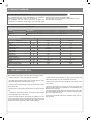
Code Description
RE2224 24 Vdc gear motor for hinged doors with max length 2,3 m or weight 250 Kg, 230 Vac power supply
RE2224S 24 Vdc gear motor for hinged doors with max length 2,3 m or weight 250 Kg
TECHNICAL DATA
MODELS RE2224 RE2224S
TECHNICAL SPECIFICATIONS
Torque Nm 120 120
Working cycle % 80 80
Opening time at 90° sec 14-20 14-20
Control board CBX20224 -
Power supply Vac 230 -
Power supply Vdc - 24
Absorption A 0,6 2
Engine power W 115 50
Integrated lights - -
Degree of protection IP 44 44
Dimensions (L - P - H) mm 120 - 250 - 350 120 - 250 - 350
Weight Kg 10,5 8
Operating temperature °C -20°+55° -20°+55°
Leaves maximum weight Kg 250 250
2 - PRODUCT OVERVIEW
2.1 - Description of the product
The COMFORT RE gear motors are destined to be installed in
systems for the automation of gates with hinged doors.
The COMFORT RE gear motors have been designed and
constructed to be tted onto hinged doors within the weight limits
indicated in the technical specications table.
The use of gear motors for applications which dier from those
indicated above is prohibited.
2.2 - Model and technical characteristics
3 - PRELIMINARY CHECKS
Before installing this product, verify and check the following steps:
- Check that the gate or door are suitable for automation
- The weight and size of the gate or door must be within the maxi-
mum permissible operating limits specied in Fig. 2
- Check the presence and strength of the security mechanical stops
of the gate or door
- Check that the mounting area of the product is not subject to ood-
ing
- Conditions of high acidity or salinity or proximity to heat sources
could cause malfunction of the product
- Extreme weather conditions (for example the presence of snow,
ice, high temperature range, high temperatures) may increase the
friction and therefore the force required for the handling and initial
starting point may be higher than under normal conditions.
- Check that the manual operation of gate or door is smooth and
friction-free and there is no risk of derailment of the same
- Check that the gate or door are in equilibrium and stationary if left
in any position
- Check that the power line to supply the product is equipped with
proper grounding safety and protected by a magnetothermal and
dierential security device
- Provide the power system with a disconnecting device with a gap
of contacts enabling full disconnection under the conditions dictated
by the overvoltage category III.
- Ensure that all materials used for the installation comply with cur-
rent regulations

5
EN
Unscrew the cover screws (Fig.12a). Raise the back by about 1 cm
then slide it out forwards (Fig.12b).
The lights on the cover are connected by two wires, discon-
nect the terminal or lay carefully the cover upside-down on the
external part (Fig.13).
Loosen the screw of the mechanical limit switches up to when they
can slide (Fig.14).
Release the gearmotor and open manually the leaf up to the
requested opening position.
Insert the pin completely into the rst free hole close to the leaf
(Fig.15).
Move the mechanical stop up to the stop limit on the pin head
(Fig.16a) and screw again the mechanical stop (Fig.16b).
In order to adjust the stop in opening, move the leaf up to the
requested opening position and insert the pin into the rst free hole
opposite to the leaf.
Move the mechanical stop on the stop limit on the pin head (Fig.16a)
and screw it again (Fig.16b).
4.2 - Adjusting the mechanical limit switch in opening
Switch-o the power supply.
Open the cover as shown on paragraph 4.2.
By using a screwdriver, release the bottom screw of the cover
(Fig.19a).
Remove the mask and pull out the led band (Fig.19b) .
In case of installation of the second motor, follow the above mentioned instructions for the mechanical mounting, for the electrical connec-
tions refer to the Fig.21.
Disconnect the plug connector (Fig.20a).
Connect the new led stripe and insert them into the mask.
Insert the mask by placing rst the seal side and then fastening it
with the screw (Fig.20b).
4.5 - Replacing led
4.4 - Mechanical and electronic connections of the second motor
4.1 - Installation
Before starting the installation, make sure that the product is intact
and that the packaging contains all the components shown in Fig.3.
Make sure that the mounting area is compatible with the overall
dimensions (Fig.1).
Check the allowed opening angle according to the xing points of the
brackets in Fig.4 and in the diagram in Fig.5.
Fig.6 is an example of a typical system:
- Operators (1)
- Photocells (2)
- Posts for photocells (3)
- Flashing light with integrated aerial (4)
- Key or digital switch (5)
Mounting
Measure the value C (Fig. 4) = distance between the rotation fulcrum
of the leaf and the pillar surface where the rear bracket will be xed.
Move manually the leaf up to the opening required (maximum 120°):
establish the value of the maximum opening angle of each leaf.
Mark on the diagram in Fig.5 the value C and trace an horizontal
line up to intersect the area that includes the angle value measured
before.
Trace some vertical lines on the intersection points between the
horizontal line and the area in order to nd the useful values for the
dimension A (g. 4).
Chose the value A in this range.
Mark on the pillar the value A and trace a vertical line in correspon-
dence (Fig.7a).
Mounting the motor bracket to the pillar
Draw a horizontal line on the pillar in line where the leaf bracket
should be xed (Fig.7b).
Position the bracket so that the inside of the bottom edge is alig-
ned with the horizontal line shown in Fig. 7b and x it with suitable
screws and washers (not supplied) (Fig.7c).
Secure the gearmotor to the post bracket using the screw and nut
provided (Fig.8). The motor can be turned in this phase to simplify
the electrical connections (4.3 Electrical connections).
An o-axis mounting can cause malfunctioning and damage
the automation system.
Mounting the motor bracket
Fix the curved arm to the motor arm using the pin and stop ring.
Fix the gate bracket to the curved arm using the pin but without the
stop ring (Fig. 9).
Move the gate leaf up to the maximum opening position. Release
the gearmotor (Fig.10)
Completely extend the arms, position the curved arm next to the leaf
of the gate and place the gate bracket on it. Holding with one hand
the bracket in contact with the leaf, try to make a complete opening
and closing movement (Fig. 11a).
Fix the gate bracket to the leaf with suitable screws (not supplied)
and x the pin using the stop ring (Fig. 11b).
An o-axis mounting can cause malfunctioning and damage
the automation system.
4.3 - Electrical connections
Insert the supply cable (Fig.17). Connect the wires of the supply
cable to the terminal following the electrical drawing in Fig. 18.
Proceed with the other connections following the control unit’s
instructions.
Replace the cover to its original position and fasten the two xing
screws.
4 - PRODUCT INSTALLATION
WARNING
WARNING
WARNING

6
EN
5.2 Commissioning
Following the successful testing of all (and not just some) devices in
the system you can proceed with the commissioning.
You must prepare, and keep for 10 years, the technical le of the
system with the wiring diagram, drawing or photo of the system,
risks analysis and solutions adopted, manufacturer declaration of
conformity of all devices connected, instruction manual of each de-
vice and maintenance schedule of the system.
Fix on the gate or door a plaque indicating the automation data, the
name of the person responsible for the commissioning, the serial
number and year of construction, the CE mark.
Attach a plaque indicating the steps required to manually unlock the
system.
Implement and deliver to the end user the declaration of conformity,
the instructions and warnings for use for the end user and the main-
tenance schedule of the system.
Make sure the user understands proper automatic, manual and
emergency operation of the automation.
Inform the end user in writing of the dangers and risks still present.
5.1 Testing
All system components must be tested following the procedures out-
lined in the respective instruction manuals.
Check that they meet the guidelines in Chapter 1 - Safety warnings
Check that the gate or door can move freely once the automation
is unlocked, and that they are in equilibrium and stationary if left in
any position.
Check the correct operation of all connected devices (photocells,
sensitive edges, emergency buttons, etc.), testing the opening, clos-
ing and stopping of the gate or door via the connected control de-
vices (transmitters, buttons, switches).
Carry out measurements of the impact force, as prescribed by
standard EN 12453 adjusting the functions of speed, motor force
and deceleration of the unit if the measurements do not give the
desired results until you nd the right setting.
The testing of the system must be performed by qualied techni-
cians who must perform the tests required by relevant legislation
related to risks, ensuring compliance with the provisions of the regu-
lations, in particular the EN 12453 standard, which species the test-
ing methods for the automation of doors and gates.
5- TESTING AND COMMISSIONING THE AUTOMATION

7
EN
Marantec Antriebs- und Steuerungstechnik GmbH & Co. KG pro-
duces systems for the automation of gates, garage doors, automatic
doors, shutters, parking lots and road barriers. However, Marantec
is not the manufacturer of your automation system, which is rather
the result of a process of analysis, evaluation, selection of materials,
and installation performed by your own installer. Each automated
system is unique and only your installer has the experience and pro-
fessionalism required to create a system to suit your needs, safe
and reliable over time, and carried out in a workmanlike manner, i.e.
compliant with the current regulations. Even if your automation sys-
tem meets the security level required by law, this does not exclude
the existence of "residual risks", i.e. the possibility that it may cause
dangerous situations, usually as a result of improper or irresponsible
use; for this reason we would like to give you some suggestions:
• Before using the automation for the rst time, ask the installer to
explain the origin of residual risks.
• Keep this manual for future use and deliver it to any new owner of
the automation.
• Inappropriate or improper use of the automation can make it dan-
gerous: do not command the movement of the automation if people,
animals or things are in its range.
• Children: If properly designed, an automation system ensures a
high degree of security, preventing movement in the presence of
people or things with its detection systems, and ensuring always
predictable and safe activation. It is prudent to prevent children from
playing near the automation and keep remote controls out of their
reach to prevent accidental activation.
• Malfunctions: As soon as you notice any malfunctions, disconnect
the system from the power supply and operate the manual release.
Do not attempt any repairs by yourself, but require the assistance
of your installer: meanwhile, the system can operate like a non-au-
tomated opening device after releasing the motor reducer with the
release key supplied with the system.
• In case of failures or power failures: While awaiting the arrival of
your installer or the restore of the electricity, if the system is not
equipped with backup batteries, the automation can be operated as
any normal non-automated opening device. To do this, you must run
the manual release.
Release and manual movement: before performing this operation
pay attention that the device can be released only when the door is
stationary.
• Maintenance: Like any machine, your automation needs periodic
maintenance to ensure its long life and total safety. Agree with your
installer on a maintenance plan on a periodic basis; Marantec rec-
ommends a frequency of 6 months for normal domestic use, but
this period may vary depending on the intensity of use. All inspec-
tion, maintenance or repairs should be performed only by qualied
personnel.
• Do not change the system and control or programming parameters
of the automation: the responsibility lies with your installer.
• The testing, routine maintenance and any repairs must be docu-
mented by the person who performs them, and related documents
must kept by the owner.
The only interventions that are possible for the user and should be
carried out periodically are the cleaning of the slides and photocells,
as well as the removal of any leaves or rocks that could hinder the
automation. To prevent anyone from activating the gate or door,
before proceeding, remember to release the automation and clean
only with a cloth slightly dampened with water.
• Disposal: At the end of the automation useful life, make sure that
the dismantling is carried out by qualied personnel and the mate-
rials are recycled or disposed of according to local regulations in
force.
• Operate the gate or door (with remote control, key switch, etc..);
if everything is working properly, the gate or the door will open and
close normally, otherwise the ashing light ashes and the maneu-
ver does not start.
With the safeties out of use, the automation must be repaired as
soon as possible.
Replacing the remote control battery: if your remote control seems
to work worse or not work at all after a while, this may simply de-
pend on the exhaustion of the battery (depending on use, it may
take several months to over a year). In that case, you will see that
the conrmation of transmission light does not turn on, or comes on
only briey.
The batteries contain polluting substances: do not throw them in the
garbage but use the methods prescribed by local regulations.
Thank you for choosing Marantec; for more information feel free to
visit our website www.marantec.com.
6 - INSTRUCTIONS AND WARNINGS FOR THE END USER

8
DE
1
2
3
4
5
6
8
Sicherheitshinweise
2.1
2.2
4.1
4.2
4.3
4.4
4.5
5.1
5.2
Produkteinführung
Produktbeschreibung
Modell und technische Merkmale
Vorabkontrollen
Produktinstallation
Installation
Einstellung des mechanischen Endanschlags
beim Önen
Stromanschlüsse
Mechanische und elektronische Anschlüsse
des Zweitmotors
Auswechseln der LED
Ab- und Inbetriebnahme
Abnahme
Inbetriebnahme
Anweisungen und Hinweise für den
Endbenutzer
Konformitätserklärung CE
S. 9
S. 10
S. 10
S. 10
S. 10
S. 11
S. 11
S. 11
S. 11
S. 11
S. 11
S. 12
S. 12
S. 12
S. 13
S. 51
INHALTSVERZEICHNIS
7
Abbildungen S. 44

9
DE
1 - SICHERHEITSHINWEISE
ORIGINALANWEISUNGEN – Wichtige Sicherheitsanweisun-
gen. Für die Sicherheit der Personen ist es wichtig, die folgen-
den Sicherheitsanweisungen zu befolgen. Bewahren Sie diese
Anweisungen auf.
Vor Durchführung der Installation lesen Sie die Anleitung bitte
aufmerksam durch.
Die Konstruktion und die Herstellung der Geräte, aus denen
sich das Produkt zusammensetzt, und die in diesem Handbuch
enthaltenen Informationen entsprechen den geltenden Si-
cherheitsvorschriften. Dennoch können eine falsche Installa-
tion und eine falsche Programmierung schwerwiegende Ver-
letzungen bei Personen verursachen, die die Arbeit ausführen,
und bei denen, die die Anlage benutzen werden. Aus diesem
Grund ist es wichtig, während der Installation strikt alle Anwei-
sungen in diesem Handbuch zu beachten.
Bei Zweifel jeglicher Art die Installation abbrechen und ggf. den Ma-
rantec Kundendienst zur Klärung kontaktieren.
Für die europäische Gesetzgebung muss der Einbau einer au-
tomatischen Tür oder eines automatischen Tors den Bestim-
mungen der Richtlinie 2006/42/EG (Maschinenrichtlinie) und im
Besonderen den Normen EN 12453, EN 12635 und EN 13241-1
entsprechen, die eine Konformitätserklärung der Automatisie-
rung ermöglichen.
In Anbetracht dessen müssen die endgültige Verbindung der Auto-
matisierung ans Stromnetz, die Endabnahme der Anlage, die Inbe-
triebnahme und die regelmäßige Wartung von qualiziertem und
erfahrenem Personal entsprechend den Anleitungen unter „Prüfung
und Inbetriebnahme der Automatisierung“ durchgeführt werden.
Außerdem muss das Personal auch die vorgesehenen Tests nach
den vorhandenen Risiken festlegen und die Einhaltung der Gesetze,
Vorschriften und Regeln überprüfen: insbesondere die Einhaltung
der Norm EN 12453, welche die Prüfverfahren für die Automatisie-
rung von Türen und Toren festlegt.
Vor Installationsbeginn folgende Analysen und Prüfungen dur-
chführen:
Sicherstellen, dass die für die Automatisierung vorgesehenen
Vorrichtungen für die zu realisierende Anlage geeignet sind. Die-
sbezüglich aufmerksam die im Kapitel „Technische Eigenschaften“
aufgeführten Daten prüfen. Die Installation nicht durchführen, wenn
auch nur eine der Vorrichtungen nicht für den Gebrauch geeignet ist.
Sicherstellen, dass die erworbenen Vorrichtungen ausreichend sind,
um die Sicherheit und Funktion der Anlage zu gewährleisten.
Die Risikoanalyse durchführen, welche auch die Liste der Si-
cherheitsanforderungen, aufgeführt in Anhang I der Maschinenricht-
linie, beinhalten muss, und die angewandten Lösungen nennen.Die
Risikoanalyse ist eine der Unterlagen, aus denen sich die techni-
schen Unterlagen der Automatisierung zusammensetzen. Diese
müssen von einem erfahrenen Installateur ausgefüllt werden.
In Anbetracht der Gefahrensituationen, die bei Installation und
Benutzung des Produktes auftreten können, muss die Automa-
tisierung unter Berücksichtigung folgender Hinweise installiert
werden:
Keine Änderungen an der Automatisierung vornehmen, wenn diese
nicht in diesem Handbuch vorgesehen sind. Diese können nur zu
Funktionsstörungen führen. Der Hersteller übernimmt keine Haftung
für Schäden, die durch eigenmächtige Änderungen am Produkt ve-
rursacht wurden.
Ist das Stromkabel beschädigt, muss es vom Hersteller, seinem
technischen Kundendienst oder einer ähnlich qualizierten Person
ersetzt werden, um Gefährdungen zu vermeiden;
Die einzelnen Komponenten der Automatisierung dürfen nicht in
Wasser oder andere Flüssigkeiten getaucht werden. Bei der In-
stallation darauf achten, dass keine Flüssigkeit ins Innere der Vor-
richtungen dringt.
Sollten Flüssigkeiten ins Innere der Automatisierungskomponenten
dringen, sofort die Stromzufuhr abschalten und sich an den Maran-
tec Kundendienst wenden. Die Benutzung der Automatisierung in
derartigen Situationen kann gefährlich sein.
Die einzelnen Komponenten weder Wärmequellen noch oenen
Flammen aussetzen. Dadurch können Schäden, Störungen und
Gefahrensituationen entstehen oder ein Brand ausbrechen
Alle Arbeiten, die ein Önen der Schutzhülle der Komponen-
ten erfordern, müssen bei abgeschalteter Stromzufuhr dur-
chgeführt werden. Sollte die Abschaltvorrichtung nicht sichtbar
sein, ein Schild mit der Aufschrift „IN WARTUNG“ anbringen.
Alle Vorrichtungen müssen mit einer Stromleitung verbunden wer-
den, die sicher geerdet ist.
Dieses Produkt kann nicht als ausreichendes System für den
Einbruchsschutz angesehen werden. Wenn Sie sich ausreichend
schützen wollen, müssen andere Vorrichtungen in die Automatisie-
rung integriert werden.
Wie im Absatz „Prüfung und Inbetriebnahme der Automatisierung“
vorgesehen, darf das Produkt erst nach der „Inbetriebnahme“ der
Automatisierung benutzt werden.
Im Stromnetz der Anlage eine Abschaltvorrichtung mit ausreichen-
dem Önungsabstand der Kontakte vorsehen, die, wie von der
Überspannungskategorie III gefordert, die komplette Abschaltung
erlaubt.
Verwenden Sie für die Verbindung von steifen und exiblen Rohren
oder Kabeldurchgängen Anschlüsse mit dem Schutzgrad IP55 oder
höher.
Die elektrische Anlage vor der Automatisierung muss den geltenden
Bestimmungen entsprechen und fachgerecht ausgeführt sein.
Angeraten ist ein Notschalter, der in der Nähe der Automatisierung
angebracht wird (verbunden mit dem Eingang STOP der Steuerpla-
tine), so dass ein sofortiges Anhalten bei Gefahr möglich ist.
Diese Vorrichtung eignet sich nicht für Personen (einschließlich
Kinder) mit eingeschränkten körperlichen, geistigen oder Sin-
nesfähigkeiten, oder denen die nötige Erfahrung oder die Kennt-
nisse fehlen, es sei denn, sie werden von einer für ihre Sicherheit
verantwortlichen Person begleitet oder beaufsichtigt oder in der Be-
nutzung der Vorrichtung unterwiesen.
Vergewissern Sie sich vor der Inbetriebsetzung der Automatisie-
rung, dass sich keine Personen in unmittelbarer Nähe benden;
Vor jeder Reinigung und Wartung ist die Automatisierung vom
Stromnetz zu trennen;
Besondere Vorsicht ist geboten, um Quetschungen zwischen dem
geführten Teil und festen Elementen in der unmittelbaren Nähe zu
vermeiden;
Kinder sollten beaufsichtigt werden, um sicherzustellen, dass sie
nicht mit dem Gerät spielen.
Verwenden Sie nicht, wenn eine Reparatur oder Einstellung er-
forderlich ist.
Das Verpackungsmaterial aller Automatisierungskomponenten
muss entsprechend den örtlichen Bestimmungen entsorgt wer-
den.
Die Daten und Informationen in diesem Handbuch können je-
derzeit ohne Vorankündigung seitens Marantec Antriebs- und
Steuerungstechnik GmbH & Co. KG geändert werden.
ACHTUNG
ACHTUNG
ACHTUNG
ACHTUNG
ACHTUNG
ACHTUNG

10
DE
Artikelnummer Beschreibung
RE2224
24 VDC Antrieb für Drehügel mit einer Länge von max. 2,3 m oder einem Gewicht von 250 kg,
230 VAC Spannungsversorgung
RE2224S 24 VDC Antrieb für Drehügel mit einer Länge von max. 2,3 m oder einem Gewicht von 250 kg
TECHNISCHE DATEN
MODELL RE2224 RE2224S
TECHNISCHE MERKMALE
Drehmoment Nm 120 120
Arbeitszyklus % 80 80
Önungszeit auf 90 sec 14-20 14-20
Steuerung CBX20224 -
Spannungsversorgung Vac 230 -
Spannungsversorgung Vdc - 24
Motorstromaufnahme A 0,6 2
Motorleistung W 115 50
Integriertes Licht - -
Schutzart IP 44 44
Abmessungen (B - T - H) mm 120 - 250 - 350 120 - 250 - 350
Gewicht Kg 10,5 8
Betriebstemperatur °C -20°+55° -20°+55°
Maximale Türgewicht Kg 250 250
2.1 - Produktbeschreibung
Die Antriebe COMFORT RE sind für den Einbau in Automatisie-
rungsanlagen für Tore mit Drehügeln bestimmt.
Die Antriebe COMFORT RE sind zur Montage an Drehügeln in-
nerhalb der in der Tabelle der technischen Spezikationen aufgeführ-
ten Gewichtsgrenzen entworfen und gebaut.
Die Verwendung der Antriebe für andere Anwendungen als die
oben angegebenen ist verboten.
2 - PRODUKTEINFÜHRUNG
2.2 - Modell und technische Merkmale
3 - VORABKONTROLLEN
Vor der Installation bitte folgende Punkte prüfen und kontrollieren:
- Kontrollieren ob sich Tor oder Tür für die Automatisierung eignen.
- Gewicht und Größe des Tors oder der Tür müssen innerhalb der
maximal zulässigen Einsatzgrenzen liegen, die in Abb. 2 angegeben
sind.
- Kontrolle des Vorhandenseins und der Stärke der mechanischen
Sicherheitsanschläge des Tors oder der Tür.
- Sicherstellen, dass der Befestigungsbereich nicht überutet wer-
den kann.
- Überhöhter Säure- oder Salzgehalt oder die Nähe von Wärmequel-
len können Fehlfunktion des Produktes verursachen.
- bei extremen klimatischen Verhältnissen (wie z.B. Schnee, Eis,
hohe Temperaturunterschiede, hohe Temperaturen) könnten sich
die Reibungen verstärken, deshalb könnte der Kraftaufwand für die
Bewegung und das Anlaufmoment höher sein als im Normalzustand.
- Kontrollieren, dass die manuelle Bewegung des Tors oder der Tür
üssig und ohne Reibungspunkte ist und keine Entgleisungsgefahr
besteht.
- Prüfen, dass sich das Tor oder die Tür im Gleichgewicht bendet
und folglich in jeder Stellung stillsteht.
- Prüfen, dass die Stromleitung für den Anschluss des Produkts über
eine gesicherte Erdung verfügt und mit einem Leitungsschutz- und
Dierentialschalter geschützt ist.
– Im Stromnetz der Anlage eine Abschaltvorrichtung mit ausreichen-
der Önungsweite der Kontakte vorsehen, die, wie von der Über-
spannungskategorie III gefordert, die komplette Abschaltung erlaubt.
- Sicherstellen, dass das gesamte benutzte Material den geltenden
Normen entspricht.

11
DE
Drehen Sie die Schrauben des oberen Deckels heraus (Abb. 12a).
Heben Sie den hinteren Teil um etwa 1 cm an und ziehen Sie ihn
dann nach vorne ab (Abb. 12b).
Die Lichter am Deckel sind mit zwei Drähten angeschlossen.
Lösen Sie die Klemme oder legen Sie den Deckel vorsichtig
umgedreht auf die Außenseite (Abb. 13).
Lockern Sie die Schrauben der mechanischen Endanschläge, bis
sich die Endanschläge verschieben lassen (Abb. 14). Entriegeln Sie
den Antrieb und önen Sie den Torügel von Hand bis zur gewün-
schten Önungsposition. Einstecken Stahlstift in das erste freie
Loch auf der Seite des Torügels und sie einfügen fest (Abb. 15).
Schieben Sie den mechanischen Endanschlag bis zum Anschlag
am Stahlstift Kopf (Abb. 16a) und schrauben Sie den mechanischen
Endanschlag wieder fest (Abb. 16b). Zur Einstellung des mechani-
schen Endanschlags beim Schließen bewegen Sie den Torügel bis
zur gewünschten Schließposition und Einstecken Stahlstift in das
erste freie Loch auf der dem Torügel gegenüberliegenden Seite
und Sie sie einfügen fest.
Schalten Sie die Stromversorgung ab.
Önen Sie den oberen Deckel gemäß den Angaben im Absatz 4.2.
Drehen Sie die Schraube auf der Unterseite des Deckels mithilfe
eines Schraubenziehers heraus (Abb. 19a).
Nehmen Sie die Abdeckung ab und ziehen Sie den LED-Streifen
heraus (Abb. 19b).
Lösen Sie den Verbinder (Abb. 20a).
Bei Installation des Zweitmotors nehmen Sie die mechanische Befestigung entsprechend den vorgenannten Punkten vor. Bezüglich des
elektrischen Anschlusses siehe Abb. 21.
Schließen Sie die neuen LEDs an und schieben Sie sie in die
Abdeckung ein.
Setzen Sie die Abdeckung auf, indem Sie zuerst die Dichtungsseite
einschieben.
Befestigen Sie die Abdeckung anschließend mithilfe der Schraube
(Abb. 20b).
4.5 - Austausch der LED
4.4 - Mechanische und elektrische Anschlüsse des Zweitmotors
4.1 - Installation
Prüfen Sie vor dem Einbau, dass das Produkt nicht beschädigt ist
und alle Komponenten in der Packung enthalten sind (Abb. 3).
Stellen Sie außerdem sicher, dass der Befestigungsbereich des
Antriebs den Abmessungen entspricht (Abb. 1). Prüfen Sie den
zulässigen Önungswinkel entsprechend den Befestigungspunkten
der Halterungen anhand Abb. 4 und der Grak in Abb. 5.
Abb. 6 zeigt ein typisches Installationsbeispiel:
- Antriebe (1)
- Fotozellen (2)
- Standsäulen für Fotozellen (3)
- Blinkleuchte mit integrierter Antenne (4)
- Schlüsseltaster oder digitale Tastatur (5)
Positionierung des Antriebs
Messen Sie das C-Maß (Abb. 4), d. h. den Abstand zwischen dem
Drehmittelpunkt des Torügels und der Pfostenoberäche, an der
die rückseitige Halterung des Antriebs befestigt werden wird. Stellen
Sie den Torügel von Hand auf die gewünschte Önung ein (maxi-
mal 120): Hierdurch wird der Wert für den maximalen Önungswin-
kel festgelegt. Kennzeichnen Sie in der graschen Darstellung in
Abb. 5 das ermittelte C-Maß und ziehen Sie von diesem Punkt aus
eine
horizontale Linie, bis Sie den Bereich schneiden, in dem der Wert des
zuvor gemessenen Winkels liegt. Ziehen Sie an den Schnittpunkten
zwischen der horizontalen Linie und dem Bereich vertikale Linien
und bestimmen Sie so die für das A-Maß verwendbaren Werte (Abb.
4). Wählen Sie dann einen Wert für A. Übertragen Sie den ermittelten
Wert für das A-Maß auf den Pfosten und ziehen Sie auf dieser
Position eine senkrechte Linie (Abb. 7a).
Befestigung des Pfostenbeschlags
Ziehen Sie am Pfosten eine waagerechte Linie auf derselben Höhe,
auf der sich der Beschlag für die Befestigung des Armes am Torügel
benden wird (Abb. 7b).
Den Haltebügel so positionieren, dass die Innenseite der unteren
Kante mit der Horizontallinie der Abb. 7b ausgerichtet ist und sie
dann mit den Schrauben und mit passenden Scheiben (nicht mitge-
liefert) befestigen (Abb. 7c).
Den Antrieb mit der mitgelieferten Schraube und Mutter am Pfosten-
Haltebügel befestigen. In dieser Phase besteht die Möglichkeit, den
Motor zu drehen, um die Fertigung der elektrischen Anschlüsse zu
erleichtern (4.3 Elektrische Anschlüsse).
Eine von der Achsenlinie abweichende Befestigung kann
Funktionsstörungen und eine Beschädigung der Automatisie-
rung zur Folge haben.
Befestigung des Torbeschlags
Den gebogenen Arm mit dem Bolzen und dem Feststellring am Mo-
torarm befestigen.
Den Tor-Haltebügel mit dem Bolzen aber ohne Feststellring am ge-
bogenen Arm befestigen (Abb. 9).
Bewegen Sie den Torügel auf die Position der maximalen
Schließung. Entriegeln Sie den Antrieb (Abb. 10).
Die Arme komplett ausbreiten, den gebogenen Arm dem Torügel
nähern und den Tor-Haltebügel darauf setzen. Halten Sie mit einer
Hand den Beschlag an die Tür und versuchen Sie eine vollständige
Önung und Schließung durchzuführen (Fig. 11a).
Den Tor-Haltebügel mit geeigneten Schrauben (nicht mitgeliefert)
am Torügel befestigen und den Bolzen mit dem Feststellring befe-
stigen (Abb. 11b).
Eine von der Achsenlinie abweichende Befestigung kann
Funktionsstörungen und eine Beschädigung der Automatisie-
rung zur Folge haben.
4.3 - Stromanschlüsse
Führen Sie das Stromkabel ein (Abb. 17). Schließen Sie die Drähte
des Stromkabels gemäß dem Schaltbild (Abb. 18) an der Klemmlei-
ste an. Fahren Sie mit den anderen Anschlüssen entsprechend der
Anleitung für die am Motor vorgesehene Steuerung fort.
Setzen Sie den oberen Deckel wieder auf und drehen Sie die beiden
Schrauben zur Befestigung des Deckels ein.
4.2 - Einstellung des mechanischen Endanschlags beim Önen
4 - PRODUKTINSTALLATION
ACHTUNG
ACHTUNG
ACHTUNG

12
DE
5.2 Inbetriebnahme
Nach positivem Test aller (und nicht nur einiger) Vorrichtungen der
Anlage, kann die Inbetriebnahme vorgenommen werden.
Die technischen Unterlagen der Anlage müssen ausgestellt und
für 10 Jahre aufbewahrt werden, sie umfassen den Schaltplan, die
Zeichnung oder ein Foto der Anlage, die Risikoanalyse und die je-
weiligen Lösungen, die Konformitätserklärung des Herstellers, die
Gebrauchsanweisungen einer jeden Vorrichtung und den Wartungs-
plan der Anlage.
Am Tor oder an der Tür ein Schild mit den Daten der Automation,
dem Namen des Verantwortlichen der Inbetriebnahme, der Serien-
nummer, dem Herstellungsjahr sowie dem CE-Zeichen anbringen.
Ein Schild mit den notwendigen Handgrien zur manuellen Entriege-
lung der Anlage anbringen.
Die Konformitätserklärung ausfüllen und dem Endbenutzer zusam-
men mit der Gebrauchsanweisung und dem Wartungsplan der An-
lage aushändigen.
Sicherstellen, dass der Benutzer den automatischen und manuellen
Betrieb und die Notausschaltung des Antriebs verstanden hat.
Den Endbenutzer auch schriftlich über Gefahren und Risiken infor-
mieren.
5.1 Test
Alle Komponenten der Anlage müssen entsprechend der jeweiligen
Anweisungen der Handbücher endgeprüft werden.
Kontrollieren, dass die Anweisungen des Kapitels 1 beachtet wer-
den – Anweisungen zur Sicherheit Kontrollieren, dass sich das Tor
oder die Tür nach der Entriegelung frei bewegen können und sich in
jeder Stellung im Gleichgewicht benden und stillstehen.
Die korrekte Funktion aller verbundenen Vorrichtungen (Fotozellen,
Druckleisten, Notschalter und anderes) kontrollieren, indem man
mit den Bedienvorrichtungen alle Proben der Önung, Schließung
und Blockierung des Tors oder der Tür durchführt (Sender, Tasten,
Wahlschalter).
Die Messungen der Aufprallstärke nach EN 12453 durchführen, da-
bei Geschwindigkeit, Motorkraft und Verlangsamungen des Steuer-
geräts einstellen, falls die Messungen nicht die gewünschten Werte
zeigen.
Die Endabnahme der Anlage muss von einem qualiziertem
Techniker durchgeführt werden, der alle von der entsprechenden
Norm geforderten Proben bzgl. der bestehenden Risiken
ausführen muss, insbesondere entsprechend EN 12453, welche die
Testmethoden für Automationen von Türen und Tore enthält.
5 – TEST UND INBETRIEBNAHME DER AUTOMATION

13
DE
Marantec Antriebs- und Steuerungstechnik GmbH & Co. KG stellt
Automationssysteme für Tore, Garagentore, automatische Türen,
Rollläden, sowie Schranken für Parkplätze oder Straßensperren
her. Marantec ist jedoch nicht der Hersteller Ihrer Automation. Sie
ist das Ergebnis von Analysen, Auswertung, Materialwahl und Anla-
genausführung des Installateurs Ihres Vertrauens Jede Automation
ist einmalig und nur Ihr Installateur besitzt die Erfahrung und not-
wendigen Kenntnisse zur Ausführung einer auf Ihre Anforderungen
zugeschnittenen Anlage, die langfristig sicher und zuverlässig und
vor allem sachgerecht arbeitet und den geltenden Bestimmungen
entspricht. Auch wenn Ihre Automation die Sicherheitsanforderun-
gen der Bestimmungen erfüllt, schließt dies ein "Restrisiko" nicht
aus. Das bedeutet, das Gefahrensituationen entstehen können, die
normalerweise auf eine unvorsichtige und sogar falsche Benutzung
zurückzuführen sind. Eben aus diesem Grund möchten wir Ihnen
einige Ratschläge zur Verhaltensweise mitgeben:
• Vor der ersten Benutzung der Automation lassen Sie sich vom Ins-
tallateur die Ursache der Restrisiken erklären.
• Heben Sie die Gebrauchsanleitung für spätere Zweifel auf und
übergeben Sie diese einem eventuellen neuen Eigentümer der Au-
tomation.
• Eine unvorsichtige und unsachgemäße Benutzung der Automation
kann sie zu einer Gefahr werden lassen: veranlassen Sie nicht die
Bewegung der Automation, wenn sich Personen, Tiere oder Gegen-
stände in ihrem Aktionskreis benden.
• Kinder: Wenn eine Automationsanlage sachgerecht geplant wurde,
gewährleistet sie auch eine hohe Sicherheitsstufe und verhindert bei
Anwesenheit von Personen oder vorhandenen Gegenständen mit
ihren Erfassungssystemen die Bewegung, dies garantiert die immer
voraussehbare und sichere Einschaltung. Vorsichtshalber sollte
man jedoch Kindern das Spielen in der Nähe der Automation ver-
bieten und um ungewollte Einschaltungen zu verhindern, sollten die
Fernbedienungen nicht in ihrer Reichweite bleiben.
• Störungen: sobald die Automation ein ungewöhnliches Verhalten
aufweist, den Strom von der Anlage nehmen und die Entriegelung
von Hand vornehmen. Keinen Reparaturversuch vornehmen, wen-
den Sie sich an den Installateur Ihres Vertrauens: in der Zwischen-
zeit kann die Anlage nach der Entriegelung des Getriebemotors mit
dem entsprechenden Schlüssel, der zum Lieferumfang gehört, mit
nicht automatisierter Önung arbeiten.
• Bei Beschädigungen oder Stromausfall: Während Sie auf den Ins-
tallateur oder die Stromrückkehr warten und die Anlage verfügt über
keine Puerbatterie, kann die Automation wie jede andere nicht au-
tomatisierte Önung arbeiten. Hierfür muss sie von Hand entriegelt
werden.
Entriegelung und manuelle Bewegung: vor diesem Eingri darauf
achten, dass die Entriegelung nur bei stillstehendem Flügel erfolgen
kann.
• Wartung: Damit sie möglichst lange und vollkommen sicher ar-
beitet, bedarf Ihre Automation, wie jedes andere Gerät, einer re-
gelmäßigen Wartung. Vereinbaren Sie mit Ihrem Installateur einen
Wartungsplan mit regelmäßigen Abständen. Marantec empehlt bei
einem normalen Hausgebrauch alle 6 Monate einen Eingri, die-
se Zeitspanne kann sich je nach Häugkeit der Benutzung ändern.
Jede Überprüfung, Wartung oder Reparatur darf nur durch fachlich
qualiziertes Personal erfolgen.
• Die Anlage, die Programmierparameter und die Regulierung der
Automation dürfen in keiner Weise verändert werden: die Verant-
wortung trägt Ihr Installateur.
• Die Endabnahme, die regelmäßigen Wartungen und eventuelle
Reparaturen müssen durch den Ausführenden belegt werden, diese
Belege müssen vom Besitzer der Anlage aufbewahrt werden.
Die einzigen Eingrie, die Sie ausführen können und wir empfehlen
Ihnen, diese vorzunehmen, ist das Reinigen der Glasscheiben der
Fotozellen und das Entfernen von Laub oder Steinen, die eine Be-
hinderung der Automation bilden könnten. Vor diesen Eingrien die
Automation entriegeln, damit niemand das Tor oder die Tür betäti-
gen kann und für die Reinigung nur ein leicht mit Wasser angefeuch-
tetes Tuch verwenden.
• Entsorgung: Wenn die Automation nicht mehr einsatzfähig ist, sor-
gen Sie dafür, dass sie durch fachlich qualiziertes Personal abge-
baut und das Material entsprechend den örtlich geltenden Bestim-
mungen wiederverwertet oder entsorgt wird.
• Die Bedienung des Tors oder der Tür (mit Fernbedienung, mit
Schlüssel-Wahlschalter, usw.) betätigen; wenn alles in Ordnung ist,
önet oder schließt sich das Tor oder die Tür ganz normal, andern-
falls blinkt das Blinklicht einige Male und die Bewegung wird nicht
ausgeführt.
Wenn die Sicherheiten nicht mehr arbeiten, muss die Automation
umgehend repariert werden.
Batterieaustausch der Fernbedienung: falls Ihre Funkbedienung
nach einiger Zeit nicht mehr gut funktionieren sollte oder überhaupt
nicht mehr funktioniert, könnte dies einfach an der leeren Batterie
liegen (vom Gebrauch abhängig, sie kann für einige Monate und bis
über ein Jahr reichen). Sie merken es an der Tatsache, dass sich
die Bestätigungsanzeige der Übertragung nicht oder nur für einen
kurzen Moment einschaltet.
Die Batterien enthalten schädliche Substanzen: nicht in den Haus-
müll werfen, sondern sie nach den örtlich vorgesehenen Bestim-
mungen entsorgen.
Wir danken Ihnen, dass Sie Marantec gewählt haben und laden Sie
ein, für weitere Informationen unsere Internetseite www.marantec.
com zu besuchen.
6 - ANWEISUNGEN UND HINWEISE FÜR DEN ENDBENUTZER

IT
14
1
2
3
4
5
6
8
Avvertenze per la sicurezza
2.1
2.2
4.1
4.2
4.3
4.4
4.5
5.1
5.2
Introduzione al prodotto
Descrizione del prodotto
Modello e caratteristiche tecniche
Veriche preliminari
Installazione del prodotto
Installazione
Regolazione del necorsa meccanico in
apertura
Connessioni elettriche
Connessioni meccaniche ed elettroniche
del secondo motore
Sostituzione led
Collaudo e messa in servizio
Collaudo
Messa in servizio
Istruzioni ed avvertenze destinate
all’utilizzatore nale
Dichiarazione CE di conformità
pag. 15
pag. 16
pag. 16
pag. 16
pag. 16
pag. 17
pag. 17
pag. 17
pag. 17
pag. 17
pag. 17
pag. 18
pag. 18
pag. 18
pag. 19
pag. 51
INDICE
7
Immagini pag. 44

IT
15
1 - AVVERTENZE PER LA SICUREZZA
ISTRUZIONI ORIGINALI – importanti istruzioni di sicurezza. Se-
guire tutte le istruzioni perchè una scorretta installazione può
portare a lesioni gravi!. Conservare queste istruzioni.
Leggere attentamente le istruzioni prima di eseguire l’installazione.
La progettazione e la fabbricazione dei dispositivi che com-
pongono il prodotto e le informazioni contenute nel presente
manuale rispettano le normative vigenti sulla sicurezza. Ciò
nonostante un’installazione e una programmazione errata pos-
sono causare gravi ferite alle persone che eseguono il lavoro
e a quelle che useranno l’impianto. Per questo motivo, durante
l’installazione, è importante seguire attentamente tutte le istru-
zioni riportate in questo manuale.
Non procedere con l’installazione se si hanno dubbi di qualunque
natura e richiedere eventuali chiarimenti al Servizio Assistenza Ma-
rantec.
Per la legislazione Europea la realizzazione di una porta au-
tomatica o un cancello automatico deve rispettare le norme
previste dalla Direttiva 2006/42/CE (Direttiva Macchine) e in
particolare, le norme EN 12453; EN 12635 e EN 13241-1, che
consentono di dichiarare la conformità dell’automazione.
In considerazione di ciò, il collegamento denitivo dell’automatismo
alla rete elettrica, il collaudo dell’impianto, la sua messa in servizio
e la manutenzione periodica devono essere eseguiti da personale
qualicato ed esperto, rispettando le istruzioni riportate nel riquadro
“Collaudo e messa in servizio dell’automazione”.
Inoltre, egli dovrà farsi carico di stabilire anche le prove previste in
funzione dei rischi presenti e dovrà vericare il rispetto di quanto
previsto da leggi, normative e regolamenti: in particolare, il rispetto
di tutti i requisiti della norma EN 12453 che stabilisce i metodi di
prova per la verica degli automatismi per porte e cancelli.
Prima di iniziare l’installazione, eettuare le seguenti analisi e
veriche:
vericare che i singoli dispositivi destinati all’automazione siano
adatti all’impianto da realizzare. Al riguardo, controllare con partico-
lare attenzione i dati riportati nel capitolo “Caratteristiche tecniche”.
Non eettuare l’installazione se anche uno solo di questi dispositivi
non è adatto all’uso;
vericare se i dispositivi acquistati sono sucienti a garantire la si-
curezza dell’impianto e la sua funzionalità;
eseguire l’analisi dei rischi che deve comprendere anche l’elenco dei
requisiti essenziali di sicurezza riportati nell’Allegato I della Direttiva
Macchine, indicando le soluzioni adottate. L’analisi dei rischi è uno
dei documenti che costituiscono il fascicolo tecnico dell’automazio-
ne. Questo dev’essere compilato da un installatore professionista.
Considerando le situazioni di rischio che possono vericarsi
durante le fasi di installazione e di uso del prodotto è necessa-
rio installare l’automazione osservando le seguenti avvertenze:
non eseguire modiche su nessuna parte dell’automatismo se non
quelle previste nel presente manuale. Operazioni di questo tipo
possono solo causare malfunzionamenti. Il costruttore declina ogni
responsabilità per danni derivanti da prodotti modicati arbitraria-
mente;
evitare che le parti dei componenti dell’automazione possano venire
immerse in acqua o in altre sostanze liquide. Durante l’installazio-
ne evitare che i liquidi possano penetrare all’interno dei dispositivi
presenti;
se il cavo di alimentazione risulta danneggiato esso deve essere
sostituito dal costruttore o dal suo servizio di assistenza tecnica o
comunque da una persona con qualica similare in modo da preve-
nire ogni rischio;
se sostanze liquide penetrano all’interno delle parti dei componenti
dell’automazione, scollegare immediatamente l’alimentazione elet-
trica e rivolgersi al Servizio Assistenza Marantec. L’utilizzo dell’auto-
mazione in tali condizioni può causare situazioni di pericolo;
non mettere i vari componenti dell’automazione vicino a fonti di ca-
lore né esporli a amme libere. Tali azioni possono danneggiarli ed
essere causa di malfunzionamenti, incendio o situazioni di pericolo;
Tutte le operazioni che richiedono l’apertura del guscio di pro-
tezione dei vari componenti dell’automazione, devono avveni-
re con la centrale scollegata dall’alimentazione elettrica. Se il
dispositivo di sconnessione non è a vista, apporre un cartello
con la seguente dicitura: “MANUTENZIONE IN CORSO”;
tutti i dispositivi devono essere collegati ad una linea di alimentazio-
ne elettrica dotata di messa a terra di sicurezza;
il prodotto non può essere considerato un ecace sistema di prote-
zione contro l’intrusione. Se desiderate proteggervi ecacemente, è
necessario integrare l’automazione con altri dispositivi;
il prodotto può essere utilizzato esclusivamente dopo che è stata
eettuata la “messa in servizio” dell’automazione, come previsto nel
paragrafo “Collaudo e messa in servizio dell’automazione”;
prevedere nella rete di alimentazione dell’impianto un dispositivo di
disconnessione con una distanza di apertura dei contatti che con-
senta la disconnessione completa nelle condizioni dettate dalla ca-
tegoria di sovratensione III;
per la connessione di tubi rigidi e essibili o passacavi utilizzare rac-
cordi conformi al grado di protezione IP55 o superiore;
l’impianto elettrico a monte dell’automazione deve rispondere alle
vigenti normative ed essere eseguito a regola d’arte;
si consiglia di utilizzare un pulsante di emergenza da installare nei
pressi dell’automazione (collegato all’ingresso STOP della scheda
di comando) in modo che sia possibile l’arresto immediato in caso
di pericolo;
questo dispositivo non è destinato a essere usato da persone (bam-
bini compresi) le cui capacità siche, sensoriali o mentali siano ridot-
te, oppure con mancanza di esperienza o di conoscenza, a meno
che esse abbiano potuto beneciare, attraverso l’intermediazione di
una persona responsabile della loro sicurezza, di una sorveglianza
o di istruzioni riguardanti l’uso del dispositivo;
prima di avviare l’automazione assicurarsi che le persone non siano
nelle immediate vicinanze;
prima di procedere a qualsiasi operazione di pulizia e manutenzione
dell’automazione eseguire la disconnessione dalla rete elettrica;
particolare attenzione per evitare lo schiacciamento tra la parte gui-
data ed eventuali elementi ssi circostanti;
i bambini devono essere sorvegliati per sincerarsi che non giochino
con l’apparecchio.
Non utilizzare se è necessaria la riparazione o la regolazione.
Il materiale dell’imballaggio di tutti i componenti dell’automa-
zione deve essere smaltito nel pieno rispetto della normativa
presente a livello locale.
I dati e le informazioni indicate in questo manuale sono da ri-
tenersi suscettibili di modica in qualsiasi momento e senza
obbligo di preavviso da parte di Marantec Antriebs- und Steue-
rungstechnik GmbH & Co. KG
ATTENZIONE
ATTENZIONE
ATTENZIONE
ATTENZIONE
ATTENZIONE
ATTENZIONE

IT
16
Codice Descrizione
RE2224 Motoriduttore 24 Vdc per ante a battente con lunghezza max 2,3 m o peso 250 Kg, Alimentazione 230 Vac
RE2224S Motoriduttore 24 Vdc per ante a battente con lunghezza max 2,3 m o peso 250 Kg
2.1 - Descrizione del prodotto
I motoriduttori COMFORT RE sono destinati all’installazione in
impianti di automazione per cancelli con ante battenti.
I motoriduttori COMFORT RE sono progettati e costruiti per il mon-
taggio su ante battenti nei limiti di peso riportati nella tabella delle
speciche
tecniche.
É vietato l’utilizzo dei motoriduttori per applicazioni dierenti da
quelle sopra indicate.
2.2 - Modello e caratteristiche tecniche
DATI TECNICI
MODELLI RE2224 RE2224S
SPECIFICHE TECNICHE
Coppia Nm 120 120
Ciclo di lavoro % 80 80
Tempo di apertura a 90° sec 14-20 14-20
Centrale di comando CBX20224 -
Alimentazione Vac 230 -
Alimentazione Vdc - 24
Frequenza Hz 50/60 Hz -
Assorbimento motore A 0,6 2
Potenza motore W 115 50
Luce integrata - -
Grado di protezione IP 44 44
Dimensioni (L - P - H) mm 120 - 250 - 350 120 - 250 - 350
Peso Kg 10,5 8
Temperatura di esercizio °C -20°+55° -20°+55°
Peso massimo anta Kg 250 250
3 - VERIFICHE PRELIMINARI
Prima di installare il prodotto vericare e controllare i seguenti punti:
- Controllare che il cancello o la porta siano adatti ad essere auto-
matizzati
- Il peso e la dimensione del cancello o della porta devono rientrare
nei limiti d’impiego massimi consentiti indicati in Fig.2
- Controllare la presenza e la solidità degli arresti meccanici di sicu-
rezza del cancello o della porta
- Vericare che la zona di ssaggio del prodotto non sia soggetta ad
allagamenti
- Condizioni di elevata acidità o salinità o la vicinanza a fonti di calo-
re potrebbero causare malfunzionamenti del prodotto
- In caso di condizioni climatiche estreme (per esempio in presenza
di neve, ghiaccio, elevata escursione termica, temperature eleva-
te) gli attriti potrebbero aumentare e quindi la forza necessaria per
la movimentazione e lo spunto iniziale potrebbe essere superiori a
quella necessaria in condizioni normali.
- Controllare che la movimentazione manuale del cancello o della
porta sia uida e priva di zone di maggiore attrito o vi sia rischio di
deragliamento dello stesso
- Controllare che il cancello o la porta siano in equilibrio e rimangano
quindi fermi se lasciati in qualsiasi posizione
- Vericare che la linea elettrica a cui sarà collegato il prodotto sia
provvista di opportuna messa a terra di sicurezza e protetta da un
dispositivo magnetotermico e dierenziale
- Prevedere nella rete di alimentazione dell'impianto un dispositi-
vo di disconnessione con una distanza di apertura dei contatti che
consenta la disconnessione completa nelle condizioni dettate dalla
categoria di sovratensione III.
- Vericare che tutto il materiale utilizzato per l’installazione sia con-
forme alle normative vigenti
2 - INTRODUZIONE AL PRODOTTO

IT
17
4 - INSTALLAZIONE DEL PRODOTTO
Svitare le viti del coperchio superiore (Fig.12a). Alzare la parte
posteriore di circa 1 cm, quindi slarlo in avanti (Fig.12b).
Le luci del coperchio sono collegate tramite due li, scollegare
il morsetto oppure appoggiare il coperchio con attenzione sotto-
sopra sul lato esterno (Fig.13).
Allentare le viti di necorsa meccanici no a quando i necorsa sono
in grado di scorrere (Fig.14).
Sbloccare il motoriduttore e aprire manualmente l’anta no al punto
di apertura desiderato.
Inserire il perno in dotazione nel primo foro libero verso
l’anta no a inserirlo completamente (Fig.15). Portare il necorsa
meccanico in battuta sulla testa del perno (Fig.16a) e riavvitare il
necorsa meccanico (Fig.16b).
Per regolare il necorsa meccanico in chiusura, portare l’anta no
al punto di chiusura desiderato e inserire il perno in dotazione nel
primo foro libero opposto all’anta no a inserirlo completamente.
Portare il necorsa meccanico in battuta sulla testa del perno
(Fig.16a) e riavvitare il necorsa meccanico (Fig.16b).
Togliere l’alimentazione elettrica.
Aprire il coperchio superiore come indicato nel paragrafo 4.2.
Con l’aiuto di un cacciavite svitare la vite inferiore del coperchio
(Fig.19a).
Estrarre la mascherina e slare la striscia led (Fig.19b) .
Nel caso di installazione del secondo motore seguire i punti precedentamente indicati per il ssaggio meccanico, per la connessione
elettrica fare riferimento alla Fig.21.
Scollegare il connettore (Fig.20a).
Collegare i nuovi led e inserirli nella mascherina.
Inserire la mascherina inserendo prima il lato guarnizione e
successivamente ssandola con la vite (Fig.20b).
4.5 - Sostituzione led
4.4 - Connessioni meccaniche ed elettriche del secondo motore
4.1 - Installazione
Prima di procedere con l’installazione, vericare l’integrità del
prodotto e che tutti i componenti siano presenti nella confezione
(Fig.3).
Vericare inoltre che la zona di ssaggio del motoriduttore sia
compatibile con le dimensioni di ingombro (Fig.1).
Vericare l’angolo di apertura consentito in base ai punti di ssaggio
delle stae tramite Fig.4 e il graco di Fig.5.
In Fig.6 è rappresentato un esempio di installazione tipica:
- Motoriduttori (1)
- Fotocellule (2)
- Colonnine per fotocellule (3)
- Lampeggiante con antenna integrata (4)
- Selettore a chiave o tastiera digitale (5)
Posizionamento del motoriduttore
Misurare la quota C (Fig. 4) = distanza tra il fulcro di rotazione
dell’anta e la supercie del pilastro dove verrà ssata la staa
posteriore del motoriduttore.
Portare manualmente l’anta no all’apertura desiderata (massimo
120°): determinando il valore dell’angolo massimo di apertura.
Segnare nel graco di Fig.5 la quota C trovata e tracciare da questo
punto una linea orizzontale no ad intersecare l’area che comprende
il valore dell’angolo misurato precedentemente.
Nei punti d’intersezione tra la linea orizzontale e l’area, tracciare
delle linee verticali determinando i valori utilizzabili per la quota A
(g. 4). Quindi, scegliere un valore di A.
Riportare sul pilastro il valore trovato della quota A e tracciare in
corrispondenza una linea verticale (Fig.7a).
Fissaggio staa pilastro
Tracciare sul pilastro una linea orizzontale alla stessa altezza in cui
verrà a trovarsi la staa di ssaggio del braccio sull’anta del cancello
(Fig.7b).
Posizionare la staa in modo che l’interno del bordo inferiore sia
allineata con la linea orizzontale di Fig. 7b e ssarla utilizzando viti e
rondelle adeguate (non fornite) (Fig.7c).
Fissare il motoriduttore alla staa pilastro con la vite e il dado in
dotazione (Fig.8). In questa fase, è possibile ruotare il motore per
facilitare i collegamenti elettrici (4.3 Collegamenti elettrici).
Un ssaggio fuori asse può provocare malfunzionamenti
all’automazione e provocarne la rottura.
Fissaggio staa cancello
Fissare il braccio curvo al braccio motore tramite il perno e l’anello
di arresto.
Fissare la staa cancello al braccio curvo tramite il perno ma senza
anello di arresto (Fig. 9).
Portare l’anta del cancello nella posizione di massima chiusura.
Sbloccare il motoriduttore (Fig.10)
Estendere completamente i bracci, avvicinare il braccio curvo all’an-
ta e appoggiare su quest’ultimo la staa cancello. Tenendo con una
mano la staa a contatto con l’anta, provare a eettuare una apertu-
ra e una chiusura completa (Fig. 11a).
Fissare la staa cancello all’anta con viti adeguate (non fornite) e
ssare il perno con l’anello di arresto (Fig. 11b).
Un ssaggio non in bolla può provocare malfunzionamenti
all’automazione e provocarne la rottura.
4.3 - Connessioni elettriche
Inserire il cavo di alimentazione (Fig.17). Collegare i li del cavo di
alimentazione alla morsettiera secondo lo schema elettrico (Fig.18).
Procedere con gli altri collegamenti seguendo le istruzioni della
centrale di comando presente sul motore.
Rimettere il coperchio superiore e avvitare le n.2 viti che ssano il
coperchio.
4.2 - Regolazione del necorsa meccanico in apertura
ATTENZIONE
ATTENZIONE
ATTENZIONE

18
IT
5.2 Messa in servizio
A seguito del positivo collaudo di tutti (e non solo di alcuni) i disposi-
tivi dell’impianto si può procedere con la messa in servizio
E’ necessario realizzare e conservare per 10 anni il fascicolo tecnico
dell’impianto che dovrà contenere lo schema elettrico, il disegno o
foto dell’impianto, l’analisi dei rischi e le soluzioni adottate, la dichia-
razione di conformità del fabbricante di tutti i dispositivi collegati,
il manuale istruzioni di ogni dispositivo e il piano di manutenzione
dell’impianto
Fissare sul cancello o la porta una targa indicante i dati dell’automa-
zione, il nome del responsabile della messa in servizio, il numero di
matricola e l’anno di costruzione, il marchio CE
Fissare una targa che indichi le operazioni necessarie per sbloccare
manualmente l’impianto
Realizzare e consegnare all’utilizzatore nale la dichiarazione di
conformità , le istruzioni e avvertenze d’uso per l’utilizzatore nale e
il piano di manutenzione dell’impianto
Accertarsi che l’utilizzatore abbia compreso il corretto funzionamen-
to automatico, manuale e di emergenza dell’automazione.
Informare anche in forma scritta l’utilizzatore nale sui pericoli e ri-
schi ancora presenti
5.1 Collaudo
Tutti i componenti dell’impianto devono essere collaudati seguendo
le procedure indicate nei rispettivi manuali di istruzioni
Controllare che siano rispettate le indicazioni del Capitolo 1 – Avver-
tenze per la sicurezza
Controllare che il cancello o la porta si possano muovere liberamen-
te una volta sbloccata l’automazione e che siano in equilibrio e ri-
mangano quindi fermi se lasciati in qualsiasi posizione
Controllare il corretto funzionamento di tutti i dispositivi collegati (fo-
tocellule, bordi sensibili, pulsanti di emergenza, altro) eettuando
delle prove di apertura, chiusura e arresto del cancello o della porta
tramite i dispositivi di comando collegati (trasmettitori, pulsanti, se-
lettori)
Eettuare le misurazioni della forza d’impatto come previsto dalla
normativa EN 12453 regolando le funzioni di velocità, forza motore e
rallentamenti della centrale nel caso in cui le misurazioni non diano
i risultati desiderati no a trovare il giusto settaggio
Il collaudo dell’impianto va eseguito da un tecnico qualicato che
deve eettuare le prove richieste dalla normativa di riferimento in
funzione dei rischi presenti, vericando il rispetto di quanto previsto
dalle normative, in particolare la norma EN 12453 che indica i meto-
di di prova per gli automatismi per porte e cancelli.
5 - COLLAUDO E MESSA IN SERVIZIO DELL’AUTOMAZIONE

19
IT
Marantec Antriebs- und Steuerungstechnik GmbH & Co. KG produ-
ce sistemi per l’automazione di cancelli, porte garage, porte auto-
matiche, serrande, barriere per parcheggi e stradali. Marantec non è
però il produttore della vostra automazione, che è invece il risultato
di un’opera di analisi, valutazione, scelta dei materiali, e realizza-
zione dell’impianto eseguita dal vostro installatore di ducia. Ogni
automazione è unica e solo il vostro installatore possiede l’esperien-
za e la professionalità necessarie ad eseguire un impianto secondo
le vostre esigenze, sicuro ed adabile nel tempo, e soprattutto a
regola d’arte, rispondente cioè alle normative in vigore. Anche se
l’automazione in vostro possesso soddisfa il livello di sicurezza ri-
chiesto dalle normative, questo non esclude l’esistenza di un “ri-
schio residuo”, cioè la possibilità che si possano generare situazioni
di pericolo, solitamente dovute ad un utilizzo incosciente o addirit-
tura errato, per questo motivo desideriamo darvi alcuni consigli sui
comportamenti da seguire :
• Prima di usare per la prima volta l’automazione, fatevi spiegare
dall’installatore l’origine dei rischi residui.
• Conservate il manuale per ogni dubbio futuro e consegnatelo ad un
eventuale nuovo proprietario dell’automazione.
• Un uso incosciente ed improprio dell’automazione può farla diven-
tare pericolosa: non comandate il movimento dell’automazione se
nel suo raggio di azione si trovano persone, animali o cose.
• Bambini: Se adeguatamente progettato un impianto di automa-
zione garantisce un alto grado di sicurezza, impedendo con i suoi
sistemi di rilevazione il movimento in presenza di persone o cose, e
garantendo un’attivazione sempre prevedibile e sicura. È comunque
prudente vietare ai bambini di giocare in prossimità dell’automazio-
ne e per evitare attivazioni involontarie non lasciare i telecomandi
alla loro portata.
• Anomalie: Non appena notate qualunque comportamento anoma-
lo da parte dell’automazione, togliete alimentazione elettrica all’im-
pianto ed eseguite lo sblocco manuale. Non tentate da soli alcu-
na riparazione, ma richiedete l’intervento del vostro installatore di
ducia: nel frattempo l’impianto può funzionare come un’apertura
non automatizzata, una volta sbloccato il motoriduttore con apposita
chiave di sblocco data in dotazione con l’impianto.
• In caso di rotture o assenza di alimentazione: Attendendo l’inter-
vento del vostro installatore, o il ritorno dell’energia elettrica se l’im-
pianto non è dotato di batterie tampone, l’automazione può essere
azionata come una qualunque apertura non automatizzata. Per fare
ciò è necessario eseguire lo sblocco manuale.
• Sblocco e movimento manuale: prima di eseguire questa operazio-
ne porre attenzione che lo sblocco può avvenire solo quando l’anta
è ferma.
• Manutenzione: Come ogni macchinario la vostra automazione ha
bisogno di una manutenzione periodica anché possa funzionare
più a lungo possibile ed in completa sicurezza. Concordate con il vo-
stro installatore un piano di manutenzione con frequenza periodica;
Marantec consiglia un intervento ogni 6 mesi per un normale utilizzo
domestico, ma questo periodo può variare in funzione dell’intensità
d’uso. Qualunque intervento di controllo, manutenzione o riparazio-
ne deve essere eseguito solo da personale qualicato.
• Non modicate l’impianto ed i parametri di programmazione e di
regolazione dell’automazione: la responsabilità è del vostro instal-
latore.
• Il collaudo, le manutenzioni periodiche e le eventuali riparazioni de-
vono essere documentate da chi le esegue e i documenti conservati
dal proprietario dell’impianto.
Gli unici interventi che vi sono possibili e vi consigliamo di eettuare
periodicamente sono la pulizia dei vetrini delle fotocellule e la rimo-
zione di eventuali foglie o sassi che potrebbero ostacolare l’auto-
matismo. Per impedire che qualcuno possa azionare il cancello o la
porta, prima di procedere, ricordatevi di sbloccare l’automatismo e di
utilizzare per la pulizia solamente un panno leggermente inumidito
con acqua.
• Smaltimento: Al termine della vita dell’automazione, assicuratevi
che lo smaltimento sia eseguito da personale qualicato e che i ma-
teriali vengano riciclati o smaltiti secondo le norme valide a livello
locale.
• Azionare il comando del cancello o della porta (con telecomando,
con selettore a chiave, ecc.); se tutto è a posto il cancello o la porta
si aprirà o chiuderà normalmente, altrimenti il lampeggiante farà al-
cuni lampeggi e la manovra non partirà.
Con le sicurezze fuori uso è necessario far riparare quanto prima
l’automatismo.
Sostituzione pila del telecomando: se il vostro trasmettitore dopo
qualche tempo vi sembra funzionare peggio, oppure non funzionare
aatto, potrebbe semplicemente dipendere dall’esaurimento della
pila (a seconda dell’uso, possono trascorrere da diversi mesi no
ad oltre un anno). Ve ne potete accorgere dal fatto che la spia di
conferma della trasmissione non si accende, oppure si accende solo
per un breve istante.
Le pile contengono sostanze inquinanti: non gettarle nei riuti comu-
ni ma utilizzare i metodi previsti dai regolamenti locali.
Vi ringraziamo per aver scelto Marantec e vi invitiamo a visitare il
nostro sito internet www.marantec.com per ulteriori informazioni.
6 - ISTRUZIONI ED AVVERTENZE DESTINATE ALL’UTILIZZATORE FINALE

20
FR
1
2
3
4
5
6
8
Avertissements pour la sécurité
2.1
2.2
4.1
4.2
4.3
4.4
4.5
5.1
5.2
Introduction au produit
Description du produit
Modèle et caractéristiques
techniques
Contrôles préliminaires
Installation du produit
Installation
Réglage du n de course mécanique en
ouverture
Connexions électriques
Connexions mécaniques et électriques du
deuxième moteur
Remplacement led
Essai et mise en service
Essai
Mise en service
Instructions et avertissements
destinés à l'utilisateur nal
Déclaration CE de conformité
page 21
page 22
page 22
page 22
page 22
page 23
page 23
page 23
page 23
page 23
page 23
page 24
page 24
page 24
page 25
page 51
SOMMAIRE
7
Images page 44
La pagina si sta caricando...
La pagina si sta caricando...
La pagina si sta caricando...
La pagina si sta caricando...
La pagina si sta caricando...
La pagina si sta caricando...
La pagina si sta caricando...
La pagina si sta caricando...
La pagina si sta caricando...
La pagina si sta caricando...
La pagina si sta caricando...
La pagina si sta caricando...
La pagina si sta caricando...
La pagina si sta caricando...
La pagina si sta caricando...
La pagina si sta caricando...
La pagina si sta caricando...
La pagina si sta caricando...
La pagina si sta caricando...
La pagina si sta caricando...
La pagina si sta caricando...
La pagina si sta caricando...
La pagina si sta caricando...
La pagina si sta caricando...
La pagina si sta caricando...
La pagina si sta caricando...
La pagina si sta caricando...
La pagina si sta caricando...
La pagina si sta caricando...
La pagina si sta caricando...
La pagina si sta caricando...
La pagina si sta caricando...
-
 1
1
-
 2
2
-
 3
3
-
 4
4
-
 5
5
-
 6
6
-
 7
7
-
 8
8
-
 9
9
-
 10
10
-
 11
11
-
 12
12
-
 13
13
-
 14
14
-
 15
15
-
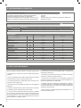 16
16
-
 17
17
-
 18
18
-
 19
19
-
 20
20
-
 21
21
-
 22
22
-
 23
23
-
 24
24
-
 25
25
-
 26
26
-
 27
27
-
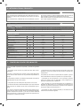 28
28
-
 29
29
-
 30
30
-
 31
31
-
 32
32
-
 33
33
-
 34
34
-
 35
35
-
 36
36
-
 37
37
-
 38
38
-
 39
39
-
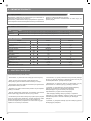 40
40
-
 41
41
-
 42
42
-
 43
43
-
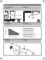 44
44
-
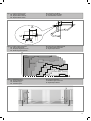 45
45
-
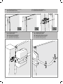 46
46
-
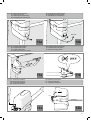 47
47
-
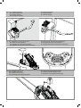 48
48
-
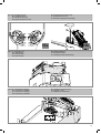 49
49
-
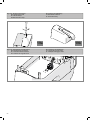 50
50
-
 51
51
-
 52
52


Marantec Comfort RE2224 Manuale del proprietario
- Tipo
- Manuale del proprietario
- Questo manuale è adatto anche per
in altre lingue
- English: Marantec Comfort RE2224 Owner's manual
- français: Marantec Comfort RE2224 Le manuel du propriétaire
- español: Marantec Comfort RE2224 El manual del propietario
- Deutsch: Marantec Comfort RE2224 Bedienungsanleitung
- português: Marantec Comfort RE2224 Manual do proprietário
- polski: Marantec Comfort RE2224 Instrukcja obsługi
Documenti correlati
-
Marantec Comfort REP2224S Manuale del proprietario
-
-
-
-
-
-
-
-
-
Altri documenti
-
 Key Automation 580STAR500W Manuale utente
-
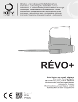 Key Automation 580REP Manuale utente
-
Key Gates Star 200 Guida utente
-
-
-
-
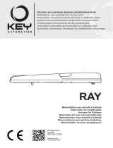 Key Automation 580RAY Manuale utente
-
 Key Automation 580STAR3024W Manuale utente
-
 Key Automation 580ISSTAR500 Manuale utente
-
Tau T-One Manuale del proprietario


