Key Automation 580STAR3024W Manuale utente
- Tipo
- Manuale utente

COMFORT ST
ST3024
Gear motor for hinged gates
Antriebe für Drehtore
Motoriduttore per cancelli a battente
Motorreductor para cancelas batientes
Motoréducteur pour portails à battants
Motorredutores para portões de batente
Motoreduktor do bram skrzydłowych
Motoriduttore interrato
Under grounded gear motor
Motoreducteur enterré
Motorreductor interrado
Unrterflur-Drehtorantrieb
Motorredutor interrado
Podziemny motoreduktor
UNDER
Istruzioni ed avvertenze per l’installazione e l’uso
Instructions and warnings for installation and use
Instrucciones y advertencias para su instalación y uso
Anleitungen und Hinweise zu Installation und Einsatz
Instruções e advertências para a instalação e utilização
Instructions et avertissements pour l’installation et l’usage
Management
System
ISO 9001:2008
www.tuv.com
ID 9105043769
Instructions and warnings for installation and use
Anleitungen und Hinweise zu Installation und Einsatz
Istruzioni ed avvertenze per l’installazione e l’uso
Instructions et avertissements pour l’installation et l’usage
Instrucciones y advertencias para su instalación y uso
Instruções e advertências para a instalação e utilização
Instrukcje i zalecenia dotyczące instalacji i użytkowania

2
EN
1
2
3
4
5
7
Safety warnings
2.1
2.2
4.1
4.2
5.1
5.2
Product overview
Product description
Technical characteristics
Preliminary checks
Installing the product
Installation
Electrical connections
Testing and commissioning
Testing
Commissioning
EC Declaration of Conformity
p. 3
p. 4
p. 4
p. 4
p. 4
p. 5
p. 5
p. 5
p. 6
p. 6
p. 6
p. 48
INDEX
6Figures p. 44

3
EN
1 - SAFETY WARNINGS
ORIGINAL INSTRUCTIONS - important safety instructions. Fol-
low the instructions since incorrect installation can lead to se-
vere inquiry! Save these instructions.
Read the instructions carefully before proceeding with installation.
The design and manufacture of the devices making up the
product and the information in this manual are compliant with
current safety standards. However, incorrect installation or
programming may cause serious injury to those working on or
using the system. Compliance with the instructions provided
here when installing the product is therefore extremely impor-
tant.
If in any doubt regarding installation, do not proceed and contact the
Marantec Technical Service for clarications.
Under European legislation, an automatic door or gate system
must comply with the standards envisaged in the Directive
2006/42/EC (Machinery Directive) and in particular standards
EN 12453; EN 12635 and EN 13241-1, which enable declaration
of presumed conformity of the automation system.
Therefore, nal connection of the automation system to the electri-
cal mains, system testing, commissioning and routine maintenance
must be performed by skilled, qualied personnel, in observance of
the instructions in the “Testing and commissioning the automation
system” section.
The aforesaid personnel are also responsible for the tests required
to verify the solutions adopted according to the risks present, and for
ensuring observance of all legal provisions, standards and regula-
tions, with particular reference to all requirements of the EN 12453
standard which establishes the test methods for testing door and
gate automation systems.
Before starting installation, perform the following checks and
assessments:
ensure that every device used to set up the automation system is
suited to the intended system overall. For this purpose, pay special
attention to the data provided in the “Technical specications” sec-
tion. Do not proceed with installation if any one of these devices is
not suitable for its intended purpose;
check that the devices purchased are sucient to guarantee system
safety and functionality;
perform a risk assessment, including a list of the essential safety
requirements as envisaged in Annex I of the Machinery Directive,
specifying the solutions adopted. The risk assessment is one of the
documents included in the automation system’s technical le. This
must be compiled by a professional installer.
Considering the risk situations that may arise during instal-
lation phases and use of the product, the automation system
must be installed in compliance with the following safety pre-
cautions:
never make modications to any part of the automation system other
than those specied in this manual. Operations of this type can only
lead to malfunctions. The manufacturer declines all liability for da-
mage caused by unauthorised modications to products;
if the power cable is damaged, it must be replaced by the manufac-
turer or its after-sales service, or in all cases by a person with similar
qualications, to prevent all risks;
do not allow parts of the automation system to be immersed in water
or other liquids. During installation ensure that no liquids are able to
enter the various devices;
should this occur, disconnect the power supply immediately and
contact a Marantec Service Centre. Use of the automation system in
these conditions may cause hazards;
never place automation system components near to sources of heat
or expose them to naked lights. This may damage system compo-
nents and cause malfunctions, re or hazards;
The drive shall be disconnected from its power source during
cleaning, maintenance and when replacing parts. If the discon-
nect device is not in a visible location, ax a notice stating:
“MAINTENANCE IN PROGRESS”:
connect all devices to an electric power line equipped with an
earthing system;
the product cannot be considered to provide eective protection
against intrusion. If eective protection is required, the automation
system must be combined with other devices;
the product may not be used until the automation system “commis-
sioning” procedure has been performed as specied in the “Automa-
tion system testing and commissioning” section;
the system power supply line must include a circuit breaker device
with a contact gap allowing complete disconnection in the conditions
specied by class III overvoltage;
use unions with IP55 or higher protection when connecting hoses,
pipes or cable glands;
the electrical system upstream of the automation system must com-
ply with the relevant regulations and be constructed to good wor-
kmanship standards;
this appliance can be used by children aged from 8 years and above
and persons with reduced physical, sensory or mental capabilities or
lack of experience and knowledge if they have been given supervi-
sion or instruction concerning use of the appliance in a safe way and
understand the hazards involved;
before starting the automation system, ensure that there is no-one
in the immediate vicinity;
before proceeding with any cleaning or maintenance work on the
automation system, disconnect it from the electrical mains;
special care must be taken to avoid crushing between the part ope-
rated by the automation system and any xed parts around it;
children must be supervised to ensure that they do not play with the
equipment.
that the drive cannot be used with a driven part incorporating a wi-
cket door unless the drive can only be operated with the wicket door
in the safe position.
ATTENTION !
Frequently examine the installation for imbalance where ap-
plicable and signs of wear or damage to cables, springs and
mounting.
Do not use if repair or adjustment is necessary.
The automation system component packaging material must
be disposed of in full observance of current local waste dispo-
sal legislation.
Marantec reserves the right to amend these instructions if ne-
cessary; they and/or any more recent versions are available at
www.marantec.com
ATTENTION !
ATTENTION !
ATTENTION !
ATTENTION !

4
EN
2 - PRODUCT OVERVIEW
2.1 - Description of the product
The COMFORT ST gear motors are destined to be installed in sys-
tems for the automation of gates with hinged doors.
The COMFORT ST gear motors have been designed and construct-
ed to be tted onto hinged doors within the weight limits indicated in
the technical specications table.
The use of gear motors for applications which dier from those indi-
cated above is prohibited.
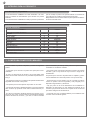
2.2 - Technical characteristics
3 - PRELIMINARY CHECKS
Before installing this product, verify and check the following steps:
- Check that the gate or door are suitable for automation
- The weight and size of the gate or door must be within the maxi-
mum permissible operating limits specied in Fig. 2
- Check the presence and strength of the security mechanical stops
of the gate or door
- Check that the mounting area of the product is not subject to ood-
ing
- Conditions of high acidity or salinity or proximity to heat sources
could cause malfunction of the product
- Extreme weather conditions (for example the presence of snow,
ice, high temperature range, high temperatures) may increase the
friction and therefore the force required for the handling and initial
starting point may be higher than under normal conditions.
- Check that the manual operation of gate or door is smooth and
friction-free and there is no risk of derailment of the same
- Check that the gate or door are in equilibrium and stationary if left
in any position
- Check that the power line to supply the product is equipped with
proper grounding safety and protected by a magnetothermal and
dierential security device
- Provide the power system with a disconnecting device with a gap
of contacts enabling full disconnection under the conditions dictated
by the overvoltage category III.
- Ensure that all materials used for the installation comply with cur-
rent regulations
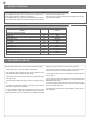
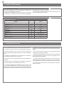
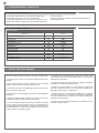
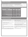
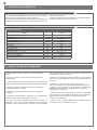
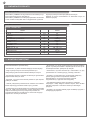
TECHNICAL DATA
MODELS ST3024
TECHNICAL SPECIFICATIONS
Speed cm/s 2,5
Thrust Force N1400
Working cycle % 80
Opening time at 90° sec adjustable
Control unit CBX20224L
Power supply (Vdc) (24)
Absorption A 3,5
Engine power W 85
Degree of protection IP 54
Dimensions (L - P - H) mm 796 - 115 - 177
Weight Kg 3,2
Operating temperature °C -20°+55
Leaves maximum weight Kg 400

5
EN
ù
4 - PRODUCT INSTALLATION
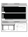
4.2 - Electrical connections
Insert the supply cable to the terminal. Connect the wires of the supply cable to the terminal following the electrical drawing in Fig. 9.
4.1 - Installation
Before proceeding with the installation, check the integrity of the
product and that all components are present in the package.
Also make sure that the mounting area of the gear motor is compat-
ible with the dimensions (Fig.1).
Ensure that leaf travel is limited, on opening and closing, by mecha-
nical stops securely anchored to the ground.
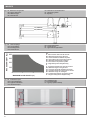
Check the permitted opening angle, based on the mounting points of
the brackets with the graph (Fig.4).
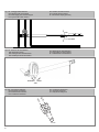
Fig.3 shows a typical installation:
- Gear motors
- Photocells
- Columns for photocells
- Flashing light with antenna
- Key switch or digital keypad
- Control unit
Installing the rear xing bracket
The xing position of the rear bracket is determined according to the
graph (Fig. 4).
Important: installations where the values of “A” and “B” (Fig. 5) are
as similar to each other as possible are preferred.
If necessary, cut the rear bracket (Fig. 6) to obtain the value “B”, then
weld the xing bracket to the wall.
Secure the bracket to the wall using welding, screws or bolts (not
included).
Installing the front xing bracket
The front bracket must be xed to the door according to dimension
“E” (Fig.5).
Installing the gear motor
Place the gear motor against the rear bracket and insert the xing
screw.
Insert the pin of the sliding bracket into the bush of the front bracket
and secure it with the screw and washer provided.
Tighten the screw on the rear bracket previously mounted with the
nut.
After the installing operations, release the operator and ensure that
the gate opens smoothly with no sti points and that it stops on the
mechanical travel stops obtaining the leaf openings determined by
the tting position of the operator with reference to Fig. 4.
Do not exceed the leaf opening determined by the tting posi-
tion of the operator with reference to Fig. 4, otherwise the ope-
rator may be irreversibly damaged!
ATTENZIONE !

6
EN
5.2 - Commissioning
Following the successful testing of all (and not just some) devices in
the system you can proceed with the commissioning.
You must prepare, and keep for 10 years, the technical le of the
system with the wiring diagram, drawing or photo of the system,
risks analysis and solutions adopted, manufacturer declaration of
conformity of all devices connected, instruction manual of each de-
vice and maintenance schedule of the system.
Fix on the gate or door a plaque indicating the automation data, the
name of the person responsible for the commissioning, the serial
number and year of construction, the CE mark.
Attach a plaque indicating the steps required to manually unlock the
system.
Implement and deliver to the end user the declaration of conformity,
the instructions and warnings for use for the end user and the main-
tenance schedule of the system.
Make sure the user understands proper automatic, manual and
emergency operation of the automation.
Inform the end user in writing of the dangers and risks still present.
5.1 - Testing
All system components must be tested following the procedures out-
lined in the respective instruction manuals.
Check that they meet the guidelines in Chapter 1 - Safety warnings
Check that the gate or door can move freely once the automation
is unlocked, and that they are in equilibrium and stationary if left in
any position.
Check the correct operation of all connected devices (photocells,
sensitive edges, emergency buttons, etc.), testing the opening, clos-
ing and stopping of the gate or door via the connected control de-
vices (transmitters, buttons, switches).
Carry out measurements of the impact force, as prescribed by
standard EN 12453 adjusting the functions of speed, motor force
and deceleration of the unit if the measurements do not give the
desired results until you nd the right setting.
The testing of the system must be performed by qualied techni-
cians who must perform the tests required by relevant legislation
related to risks, ensuring compliance with the provisions of the regu-
lations, in particular the EN 12453 standard, which species the test-
ing methods for the automation of doors and gates.
5 - TESTING AND COMMISSIONING THE AUTOMATION

7
EN
NOTE

8
DE
1
2
3
4
5
7
Sicherheitshinweise
2.1
2.2
4.1
4.2
5.1
5.2
Produkteinführung
Produktbeschreibung
Technische Merkmale
Vorabkontrollen
Produktinstallation
Installation
Stromanschlüsse
Ab- und Inbetriebnahme
Abnahme
Inbetriebnahme
Konformitätserklärung CE
S. 9
S. 10
S. 10
S. 10
S. 10
S. 11
S. 11
S. 11
S. 12
S. 12
S. 12
S. 48
INHALTSVERZEICHNIS
6Abbildungen S. 44

9
DE
1 - SICHERHEITSHINWEISE
ORIGINALANWEISUNGEN – Wichtige Sicherheitsanweisun-
gen. Für die Sicherheit der Personen ist es wichtig, die folgen-
den Sicherheitsanweisungen zu befolgen. Bewahren Sie diese
Anweisungen auf.
Vor Durchführung der Installation lesen Sie die Anleitung bitte
aufmerksam durch.
Die Konstruktion und die Herstellung der Geräte, aus denen
sich das Produkt zusammensetzt, und die in diesem Handbuch
enthaltenen Informationen entsprechen den geltenden Si-
cherheitsvorschriften. Dennoch können eine falsche Installa-
tion und eine falsche Programmierung schwerwiegende Ver-
letzungen bei Personen verursachen, die die Arbeit ausführen,
und bei denen, die die Anlage benutzen werden. Aus diesem
Grund ist es wichtig, während der Installation strikt alle Anwei-
sungen in diesem Handbuch zu beachten.
Bei Zweifel jeglicher Art die Installation abbrechen und ggf. den Ma-
rantec Kundendienst zur Klärung kontaktieren.
Für die europäische Gesetzgebung muss der Einbau einer au-
tomatischen Tür oder eines automatischen Tors den Bestim-
mungen der Richtlinie 2006/42/EG (Maschinenrichtlinie) und im
Besonderen den Normen EN 12453, EN 12635 und EN 13241-1
entsprechen, die eine Konformitätserklärung der Automatisie-
rung ermöglichen.
In Anbetracht dessen müssen die endgültige Verbindung der Auto-
matisierung ans Stromnetz, die Endabnahme der Anlage, die Inbe-
triebnahme und die regelmäßige Wartung von qualiziertem und
erfahrenem Personal entsprechend den Anleitungen unter „Prüfung
und Inbetriebnahme der Automatisierung“ durchgeführt werden.
Außerdem muss das Personal auch die vorgesehenen Tests nach
den vorhandenen Risiken festlegen und die Einhaltung der Gesetze,
Vorschriften und Regeln überprüfen: insbesondere die Einhaltung
der Norm EN 12453, welche die Prüfverfahren für die Automatisie-
rung von Türen und Toren festlegt.
Vor Installationsbeginn folgende Analysen und Prüfungen dur-
chführen:
Sicherstellen, dass die für die Automatisierung vorgesehenen
Vorrichtungen für die zu realisierende Anlage geeignet sind. Die-
sbezüglich aufmerksam die im Kapitel „Technische Eigenschaften“
aufgeführten Daten prüfen. Die Installation nicht durchführen, wenn
auch nur eine der Vorrichtungen nicht für den Gebrauch geeignet ist.
Sicherstellen, dass die erworbenen Vorrichtungen ausreichend sind,
um die Sicherheit und Funktion der Anlage zu gewährleisten.
Die Risikoanalyse durchführen, welche auch die Liste der Si-
cherheitsanforderungen, aufgeführt in Anhang I der Maschinenricht-
linie, beinhalten muss, und die angewandten Lösungen nennen.Die
Risikoanalyse ist eine der Unterlagen, aus denen sich die techni-
schen Unterlagen der Automatisierung zusammensetzen. Diese
müssen von einem erfahrenen Installateur ausgefüllt werden.
In Anbetracht der Gefahrensituationen, die bei Installation und
Benutzung des Produktes auftreten können, muss die Automa-
tisierung unter Berücksichtigung folgender Hinweise installiert
werden:
Keine Änderungen an der Automatisierung vornehmen, wenn diese
nicht in diesem Handbuch vorgesehen sind. Diese können nur zu
Funktionsstörungen führen. Der Hersteller übernimmt keine Haftung
für Schäden, die durch eigenmächtige Änderungen am Produkt ve-
rursacht wurden.
Ist das Stromkabel beschädigt, muss es vom Hersteller, seinem
technischen Kundendienst oder einer ähnlich qualizierten Person
ersetzt werden, um Gefährdungen zu vermeiden;
Die einzelnen Komponenten der Automatisierung dürfen nicht in
Wasser oder andere Flüssigkeiten getaucht werden. Bei der Installa-
tion darauf achten, dass keine Flüssigkeit ins Innere der Vorrichtun-
gen dringt.
Sollten Flüssigkeiten ins Innere der Automatisierungskomponenten
dringen, sofort die Stromzufuhr abschalten und sich an den Maran-
tec Kundendienst wenden. Die Benutzung der Automatisierung in
derartigen Situationen kann gefährlich sein.
Die einzelnen Komponenten weder Wärmequellen noch oenen
Flammen aussetzen. Dadurch können Schäden, Störungen und
Gefahrensituationen entstehen oder ein Brand ausbrechen
Die Einheit ist während der Reinigung, Wartung und Auswe-
chslung von Bestandteilen von der Speisung abzutrennen.
Sollte die Abschaltvorrichtung nicht sichtbar sein, ein Schild
mit der Aufschrift „IN WARTUNG“ anbringen.
Alle Vorrichtungen müssen mit einer Stromleitung verbunden wer-
den, die sicher geerdet ist.
Dieses Produkt kann nicht als ausreichendes System für den
Einbruchsschutz angesehen werden. Wenn Sie sich ausreichend
schützen wollen, müssen andere Vorrichtungen in die Automatisie-
rung integriert werden.
Wie im Absatz „Prüfung und Inbetriebnahme der Automatisierung“
vorgesehen, darf das Produkt erst nach der „Inbetriebnahme“ der
Automatisierung benutzt werden.
Im Stromnetz der Anlage eine Abschaltvorrichtung mit ausreichen-
dem Önungsabstand der Kontakte vorsehen, die, wie von der
Überspannungskategorie III gefordert, die komplette Abschaltung
erlaubt.
Verwenden Sie für die Verbindung von steifen und exiblen Rohren
oder Kabeldurchgängen Anschlüsse mit dem Schutzgrad IP55 oder
höher.
Die elektrische Anlage vor der Automatisierung muss den geltenden
Bestimmungen entsprechen und fachgerecht ausgeführt sein.
Das Gerät kann von Kindern im Alter von nicht weniger als 8 Jahren
und von Personen mit beschränkten körperlichen, sensoriellen und
geistigen Fähigkeiten oder ohne Erfahrung bzw. ohne das notwen-
dige Bewußtsein verwendet werden, vorausgesetzt, dass sie dabei
überwacht werden oder dass sie Anweisungen über den sicheren
Gebrauch des Gerätes und das Verständnis der damit verbundenen
Gefahren erhalten haben;
Vergewissern Sie sich vor der Inbetriebsetzung der Automatisie-
rung, dass sich keine Personen in unmittelbarer Nähe benden;
Vor jeder Reinigung und Wartung ist die Automatisierung vom
Stromnetz zu trennen;
Besondere Vorsicht ist geboten, um Quetschungen zwischen dem
geführten Teil und festen Elementen in der unmittelbaren Nähe zu
vermeiden;
Kinder sollten beaufsichtigt werden, um sicherzustellen, dass sie
nicht mit dem Gerät spielen.
Das Gerät darf mit einer automatisierten Tür mit eingebauter Fuß-
gängertür nicht verwendet werden.
ACHTUNG !
Die Anlage ist regelmäßig dahingehend zu prüfen, dass keine
Unwucht und Zeichen einer mechanischen Abnutzung, sowie
beschädigte Kabel, Federn und Stützelemente vorhanden sind.
Verwenden Sie nicht, wenn eine Reparatur oder Einstellung er-
forderlich ist.
Das Verpackungsmaterial aller Automatisierungskomponenten
muss entsprechend den örtlichen Bestimmungen entsorgt wer-
den.
Marantec behält sich vor, diese Anweisungen notfalls zu än-
dern; diese Anweisungen und/oder eine neuere Version ben-
den sich auf der Website www.marantec.com
ACHTUNG !
ACHTUNG !
ACHTUNG !

10
DE
2 - PRODUKTEINFÜHRUNG
2.1 - Produktbeschreibung
Die Antriebe COMFORT ST sind für den Einbau in Automationsan-
lagen für Toren mit Drehügeln bestimmt.
Die Antriebe COMFORT ST werden zur Montage an Drehügeln
innerhalb der in den Tabellen der technischen Daten aufgeführten
Gewichtsgrenzen entworfen und gebaut.
Die Verwendung der Getriebemotoren für andere Anwendungen als
den oben angegebenen ist verboten.
3 - VORABKONTROLLEN
Vor der Installation bitte folgende Punkte prüfen und kontrollieren:
- Kontrollieren ob sich Tor oder Tür für die Automatisierung eignen.
- Gewicht und Größe des Tors oder der Tür müssen innerhalb der
maximal zulässigen Einsatzgrenzen liegen, die in Abb. 2 angegeben
sind.
- Kontrolle des Vorhandenseins und der Stärke der mechanischen
Sicherheitsanschläge des Tors oder der Tür.
- Sicherstellen, dass der Befestigungsbereich nicht überutet wer-
den kann.
- Überhöhter Säure- oder Salzgehalt oder die Nähe von Wärmequel-
len können Fehlfunktion des Produktes verursachen.
- bei extremen klimatischen Verhältnissen (wie z.B. Schnee, Eis,
hohe Temperaturunterschiede, hohe Temperaturen) könnten sich
die Reibungen verstärken, deshalb könnte der Kraftaufwand für die
Bewegung und das Anlaufmoment höher sein als im Normalzustand.
- Kontrollieren, dass die manuelle Bewegung des Tors oder der Tür
üssig und ohne Reibungspunkte ist und keine Entgleisungsgefahr
besteht.
- Prüfen, dass sich das Tor oder die Tür im Gleichgewicht bendet
und folglich in jeder Stellung stillsteht.
- Prüfen, dass die Stromleitung für den Anschluss des Produkts über
eine gesicherte Erdung verfügt und mit einem Leitungsschutz- und
Dierentialschalter geschützt ist.
– Im Stromnetz der Anlage eine Abschaltvorrichtung mit ausreichen-
der Önungsweite der Kontakte vorsehen, die, wie von der Über-
spannungskategorie III gefordert, die komplette Abschaltung erlaubt.
- Sicherstellen, dass das gesamte benutzte Material den geltenden
Normen entspricht.
2.2 - Technische Merkmale
TECHNISCHE DATEN
MODELL ST3024
TECHNISCHE MERKMALE
Geschwindigkeit cm/s 2,5
Schubkraft N 1400
Arbeitszyklus % 80
Önungszeit auf 90° sec einstellbar
Central Command CBX20224L
Versorgung (Vdc) (24)
Leistungsaufnahme A 3,5
Motorleistung W 85
Schutzart IP 54
Größe (L - P - H) mm 796 - 115 - 177
Gewicht Kg 3,2
Betriebstemperatur °C -20°+55
Maximale Türgewicht Kg 400

11
DE
ù
4 - PRODUKTINSTALLATION
4.1 - Installation
Prüfen Sie vor dem Einbau die Unversehrtheit des Produktes sowie
ob alle Bauteile in der Packung vorhanden sind.
Prüfen Sie außerdem, ob der Befestigungsbereich des Antriebs den
Abmessungen entspricht (Abb.1).
Sicherstellen, dass der Flügeltür beim Önen und Schließen durch
mechanische Anschläge begrenzt ist, die sicher am Boden veran-
kert sind.
Prüfen Sie den zulässigen Önungswinkel entsprechend der
Befestigungspunkte der Halterungen anhand der Zeichnung (Abb.4).
Abb. 3 zeigt ein typisches Installationsbeispiel:
- Getriebemotoren
- Fotozellen
- Säulen für Fotozellen
- Blinkleuchte mit integrierter Antenne
- Schlüsselwahlschalter oder digitale Tastatur
- Steuergerät
Montage des hinteren Befestigungsbügels
Die Position zur Befestigung des hinteren Bügels wird anhand der
Zeichnung festgelegt (Abb.4).
Wichtig: Vorzuziehen ist eine Installationsweise, bei der die Werte
für “A” und “B” (Abb. 5) möglichst nahe beieinander liegen.
Schneiden Sie bei Bedarf den hinteren Bügel (Abb. 6), so dass der
Wert “B” erzielt wird, schweißen Sie ihn dann an die Wandhalterung.
Befestigen Sie schließlich die Wandhalterung mittels Schweißen,
Schrauben oder Dübeln (nicht beiliegend).
Montage des vorderen Befestigungsbügels
Der vordere Bügel muss am Flügel entsprechend des Wertes “E” in
(Abb.5).
Installation des Getriebemotors
Legen Sie den Getriebemotor auf die hintere Halterung und fügen
Sie die Befestigungsschraube ein.
Fügen Sie den Zapfen der Gleithalterung in die Buchse des vorde-
ren Bügels ein und befestigen Sie ihn mit der beiliegenden Schrau-
be und Unterlegscheibe.
Ziehen Sie mit der Mutter die Schraube des zuvor montierten hinte-
ren Bügels fest.
Nach den Installationsarbeiten den Bediener loslassen und sicher-
stellen, dass das Tor reibungslos und ohne steife Punkte önet und
dass es an den mechanischen Anschlägen stoppt, um die durch
die Einbaulage des Bedieners anhand von Abb. 4 bestimmten
Flügelönungen zu erhalten.
Überschreiten Sie nicht die durch die Einbaulage des Bedie-
ners mit Bezug auf Abb. 4 bestimmte Flügelönung, da sonst
der Bediener irreversibel beschädigt werden kann!
4.2 - Stromanschlüsse
Führen Sie das Stromkabel ein an der Klemmleiste. Schließen Sie die Drähte des Stromkabels gemäß dem Schaltbild (Abb.9) an der
Klemmleiste an.
ACHTUNG !

12
DE
5.2 - Inbetriebnahme
Nach positivem Test aller (und nicht nur einiger) Vorrichtungen der
Anlage, kann die Inbetriebnahme vorgenommen werden.
Die technischen Unterlagen der Anlage müssen ausgestellt und
für 10 Jahre aufbewahrt werden, sie umfassen den Schaltplan, die
Zeichnung oder ein Foto der Anlage, die Risikoanalyse und die je-
weiligen Lösungen, die Konformitätserklärung des Herstellers, die
Gebrauchsanweisungen einer jeden Vorrichtung und den Wartungs-
plan der Anlage.
Am Tor oder an der Tür ein Schild mit den Daten der Automation,
dem Namen des Verantwortlichen der Inbetriebnahme, der Serien-
nummer, dem Herstellungsjahr sowie dem CE-Zeichen anbringen.
Ein Schild mit den notwendigen Handgrien zur manuellen Entriege-
lung der Anlage anbringen.
Die Konformitätserklärung ausfüllen und dem Endbenutzer zusam-
men mit der Gebrauchsanweisung und dem Wartungsplan der An-
lage aushändigen.
Sicherstellen, dass der Benutzer den automatischen und manuellen
Betrieb und die Notausschaltung des Antriebs verstanden hat.
Den Endbenutzer auch schriftlich über Gefahren und Risiken infor-
mieren.
5.1 - Test
Alle Komponenten der Anlage müssen entsprechend der jeweiligen
Anweisungen der Handbücher endgeprüft werden.
Kontrollieren, dass die Anweisungen des Kapitels 1 beachtet wer-
den – Anweisungen zur Sicherheit
Kontrollieren, dass sich das Tor oder die Tür nach der Entriegelung
frei bewegen können und sich in jeder Stellung im Gleichgewicht
benden und stillstehen.
Die korrekte Funktion aller verbundenen Vorrichtungen (Fotozellen,
Druckleisten, Notschalter und anderes) kontrollieren, indem man
mit den Bedienvorrichtungen alle Proben der Önung, Schließung
und Blockierung des Tors oder der Tür durchführt (Sender, Tasten,
Wahlschalter).
Die Messungen der Aufprallstärke nach EN 12453 durchführen, da-
bei Geschwindigkeit, Motorkraft und Verlangsamungen des Steuer-
geräts einstellen, falls die Messungen nicht die gewünschten Werte
zeigen.
Die Endabnahme der Anlage muss von einem qualiziertem
Techniker durchgeführt werden, der alle von der entsprechenden
Norm geforderten Proben bzgl. der bestehenden Risiken
ausführen muss, insbesondere entsprechend EN 12453, welche die
Testmethoden für Automationen von Türen und Tore enthält.
5 - TEST UND INBETRIEBNAHME DER AUTOMATION

13
DE
ANMERKUNGEN

IT
14
1
2
3
4
5
7
Avvertenze per la sicurezza
2.1
2.2
4.1
4.2
5.1
5.2
Introduzione al prodotto
Descrizione del prodotto
Caratteristiche tecniche
Veriche preliminari
Installazione del prodotto
Installazione
Connessioni elettriche
Collaudo e messa in servizio
Collaudo
Messa in servizio
Dichiarazione CE di conformità
pag. 15
pag. 16
pag. 16
pag. 16
pag. 16
pag. 17
pag. 17
pag. 17
pag. 18
pag. 18
pag. 18
pag. 48
INDICE
6Immagini pag. 44

IT
15
1 - AVVERTENZE PER LA SICUREZZA
ISTRUZIONI ORIGINALI – importanti istruzioni di sicurezza. Se-
guire tutte le istruzioni perchè una scorretta installazione può
portare a lesioni gravi! Conservare queste istruzioni.
Leggere attentamente le istruzioni prima di eseguire l’installazione.
La progettazione e la fabbricazione dei dispositivi che com-
pongono il prodotto e le informazioni contenute nel presente
manuale rispettano le normative vigenti sulla sicurezza. Ciò
nonostante un’installazione e una programmazione errata pos-
sono causare gravi ferite alle persone che eseguono il lavoro
e a quelle che useranno l’impianto. Per questo motivo, durante
l’installazione, è importante seguire attentamente tutte le istru-
zioni riportate in questo manuale.
Non procedere con l’installazione se si hanno dubbi di qualunque
natura e richiedere eventuali chiarimenti al Servizio Assistenza Ma-
rantec.
Per la legislazione Europea la realizzazione di una porta au-
tomatica o un cancello automatico deve rispettare le norme
previste dalla Direttiva 2006/42/CE (Direttiva Macchine) e in
particolare, le norme EN 12453; EN 12635 e EN 13241-1, che
consentono di dichiarare la conformità dell’automazione.
In considerazione di ciò, il collegamento denitivo dell’automatismo
alla rete elettrica, il collaudo dell’impianto, la sua messa in servizio
e la manutenzione periodica devono essere eseguiti da personale
qualicato ed esperto, rispettando le istruzioni riportate nel riquadro
“Collaudo e messa in servizio dell’automazione”.
Inoltre, egli dovrà farsi carico di stabilire anche le prove previste in
funzione dei rischi presenti e dovrà vericare il rispetto di quanto
previsto da leggi, normative e regolamenti: in particolare, il rispetto
di tutti i requisiti della norma EN 12453 che stabilisce i metodi di
prova per la verica degli automatismi per porte e cancelli.
Prima di iniziare l’installazione, eettuare le seguenti analisi e
veriche:
vericare che i singoli dispositivi destinati all’automazione siano
adatti all’impianto da realizzare. Al riguardo, controllare con partico-
lare attenzione i dati riportati nel capitolo “Caratteristiche tecniche”.
Non eettuare l’installazione se anche uno solo di questi dispositivi
non è adatto all’uso;
vericare se i dispositivi acquistati sono sucienti a garantire la si-
curezza dell’impianto e la sua funzionalità;
eseguire l’analisi dei rischi che deve comprendere anche l’elenco dei
requisiti essenziali di sicurezza riportati nell’Allegato I della Direttiva
Macchine, indicando le soluzioni adottate. L’analisi dei rischi è uno
dei documenti che costituiscono il fascicolo tecnico dell’automazio-
ne. Questo dev’essere compilato da un installatore professionista.
Considerando le situazioni di rischio che possono vericarsi
durante le fasi di installazione e di uso del prodotto è necessa-
rio installare l’automazione osservando le seguenti avvertenze:
non eseguire modiche su nessuna parte dell’automatismo se non
quelle previste nel presente manuale. Operazioni di questo tipo
possono solo causare malfunzionamenti. Il costruttore declina ogni
responsabilità per danni derivanti da prodotti modicati arbitraria-
mente;
evitare che le parti dei componenti dell’automazione possano venire
immerse in acqua o in altre sostanze liquide. Durante l’installazio-
ne evitare che i liquidi possano penetrare all’interno dei dispositivi
presenti;
se il cavo di alimentazione risulta danneggiato esso deve essere
sostituito dal costruttore o dal suo servizio di assistenza tecnica o
comunque da una persona con qualica similare in modo da preve-
nire ogni rischio;
se sostanze liquide penetrano all’interno delle parti dei componenti
dell’automazione, scollegare immediatamente l’alimentazione elet-
trica e rivolgersi al Servizio Assistenza Marantec. L’utilizzo dell’auto-
mazione in tali condizioni può causare situazioni di pericolo;
non mettere i vari componenti dell’automazione vicino a fonti di ca-
lore né esporli a amme libere. Tali azioni possono danneggiarli ed
essere causa di malfunzionamenti, incendio o situazioni di pericolo;
L’unità deve essere scollegata dalla fonte di alimentazione du-
rante la pulizia, la manutenzione e la sostituzione di componen-
ti. Se il dispositivo di sconnessione non è a vista, apporre un
cartello con la seguente dicitura: “MANUTENZIONE IN
CORSO”;
tutti i dispositivi devono essere collegati ad una linea di alimentazio-
ne elettrica dotata di messa a terra di sicurezza;
il prodotto non può essere considerato un ecace sistema di prote-
zione contro l’intrusione. Se desiderate proteggervi ecacemente, è
necessario integrare l’automazione con altri dispositivi;
il prodotto può essere utilizzato esclusivamente dopo che è stata
eettuata la “messa in servizio” dell’automazione, come previsto nel
paragrafo “Collaudo e messa in servizio dell’automazione”;
prevedere nella rete di alimentazione dell’impianto un dispositivo di
disconnessione con una distanza di apertura dei contatti che con-
senta la disconnessione completa nelle condizioni dettate dalla ca-
tegoria di sovratensione III;
per la connessione di tubi rigidi e essibili o passacavi utilizzare rac-
cordi conformi al grado di protezione IP55 o superiore;
l’impianto elettrico a monte dell’automazione deve rispondere alle
vigenti normative ed essere eseguito a regola d’arte;
l’apparecchio può essere utilizzato da bambini di età non inferiore a
8 anni e da persone con ridotte capacità siche, sensoriali o mentali,
o prive di esperienza o della necessaria consapevolezza, purché
sotto sorveglianza oppure dopo che le stesse abbiano ricevuto istru-
zioni relative all’uso sicuro dell’apparecchio e alla comprensione dei
pericoli ad esso inerenti;
prima di avviare l’automazione assicurarsi che le persone non siano
nelle immediate vicinanze;
prima di procedere a qualsiasi operazione di pulizia e manutenzione
dell’automazione eseguire la disconnessione dalla rete elettrica;
fare particolare attenzione per evitare lo schiacciamento tra la parte
guidata ed eventuali elementi ssi circostanti;
i bambini devono essere sorvegliati per sincerarsi che non giochino
con l’apparecchio.
l’apparecchio non può essere utilizzato con una porta guidata che
incorpora una porte pedonale.
ATTENZIONE !
Esaminare periodicamente l’impianto per vericare la presenza
di sbilanciamenti e segni di usura meccanica, danneggiamento
di cavi, molle, parti di sostegno.
Non utilizzare se è necessaria riparazione o regolazione.
Il materiale dell’imballaggio di tutti i componenti dell’automa-
zione deve essere smaltito nel pieno rispetto della normativa
presente a livello locale.
Marantec si riserva il diritto di modicare le presenti istruzioni
qualora necessario, queste e/o versione superiore si possono
trovare sul sito www.marantec.com
ATTENZIONE !
ATTENZIONE !
ATTENZIONE !
ATTENZIONE !

IT
16
2 - INTRODUZIONE AL PRODOTTO
DATI TECNICI
MODELLO ST3024
SPECIFICHE TECNICHE
Velocità cm/s 2,5
Forza di spinta N1400
Ciclo di lavoro %80
Tempo di apertura a 90° sec regolabile
Centrale di comando CBX20224L
Alimentazione (Vdc) (24)
Assorbimento motore A3,5
Potenza assorbita W85
Grado di protezione IP 54
Dimensioni (L - P - H) mm 796 - 115 - 177
Peso Kg 3,2
Temperatura di esercizio °C -20°+55
Peso massimo anta Kg 400
2.1 - Descrizione del prodotto
I motoriduttori COMFORT ST sono destinati all’installazione in
impianti di automazione per cancelli con ante battenti.
I motoriduttori COMFORT ST sono progettati e costruiti per il mon-
taggio su ante battenti nei limiti di peso riportati nella tabella delle
speciche tecniche.
E’ vietato l’utilizzo dei motoriduttori per applicazioni dierenti da
quelle sopra indicate.
2.2 - Caratteristiche tecniche
3 - VERIFICHE PRELIMINARI
Prima di installare il prodotto vericare e controllare i seguenti punti:
- Controllare che il cancello o la porta siano adatti ad essere auto-
matizzati
- Il peso e la dimensione del cancello o della porta devono rientrare
nei limiti d’impiego massimi consentiti indicati in Fig.2
- Controllare la presenza e la solidità degli arresti meccanici di sicu-
rezza del cancello o della porta
- Vericare che la zona di ssaggio del prodotto non sia soggetta ad
allagamenti
- Condizioni di elevata acidità o salinità o la vicinanza a fonti di calo-
re potrebbero causare malfunzionamenti del prodotto
- In caso di condizioni climatiche estreme (per esempio in presenza
di neve, ghiaccio, elevata escursione termica, temperature eleva-
te) gli attriti potrebbero aumentare e quindi la forza necessaria per
la movimentazione e lo spunto iniziale potrebbe essere superiori a
quella necessaria in condizioni normali.
- Controllare che la movimentazione manuale del cancello o della
porta sia uida e priva di zone di maggiore attrito o vi sia rischio di
deragliamento dello stesso
- Controllare che il cancello o la porta siano in equilibrio e rimangano
quindi fermi se lasciati in qualsiasi posizione
- Vericare che la linea elettrica a cui sarà collegato il prodotto sia
provvista di opportuna messa a terra di sicurezza e protetta da un
dispositivo magnetotermico e dierenziale
- Prevedere nella rete di alimentazione dell'impianto un dispositi-
vo di disconnessione con una distanza di apertura dei contatti che
consenta la disconnessione completa nelle condizioni dettate dalla
categoria di sovratensione III.
- Vericare che tutto il materiale utilizzato per l’installazione sia con-
forme alle normative vigenti

17
IT
ù
4 - INSTALLAZIONE DEL PRODOTTO
4.1 - Installazione
Prima di procedere con l’installazione, vericare l’integrità del pro-
dotto e che tutti i componenti siano presenti nella confezione.
Vericare inoltre che la zona di ssaggio del motoriduttore sia com-
patibile con le dimensioni di ingombro (Fig.1).
La corsa dell’anta deve essere limitata, sia in apertura che in chiusu-
ra, da arresti meccanici saldamente ssati al suolo.
Vericare l’angolo di apertura consentito, in base ai punti di ssaggio
delle stae tramite il graco (Fig.4).
In Fig.3 è rappresentato un esempio di installazione tipica:
- Motoriduttori
- Fotocellule
- Colonnine per fotocellule
- Lampeggiante con antenna incorporata
- Selettore a chiave o tastiera digitale
- Centrale di comando
Installazione staa di ssaggio posteriore
La posizione di ssaggio della staa posteriore viene determinata in
base al graco (Fig.4).
Importante: sono da preferire quelle installazioni in cui valori di “A” e
“B” (Fig.5) siano il più possibilie simili tra loro.
Se necessario, tagliare la staa posteriore (Fig.6) no ad ottenere il
valore “B”, dopodichè saldarla alla staa di ssaggio a muro.
Fissare inne la staa di ssaggio a muro tramite saldatura, viti o
tasselli (non compresi).
Inserire il cavo di alimentazione. Collegare i li del cavo di alimentazione alla morsettiera secondo lo schema elettrico (Fig.9).
Installazione staa di ssaggio anteriore
La staa anteriore deve essere ssata all’ anta in base alla quota
“E” (Fig.5).
Installazione del motoriduttore
Poggiare il motoriduttore alla staa posteriore e inserire la vite di
ssaggio.
Inserire il perno della staa di scorrimento nella boccola della staa
anteriore e ssarlo tramite la vite e la rondella in dotazione.
Serrare con il dado la vite della staa posteriore montata preceden-
temente.
Ad operazioni completate, sbloccare il motoriduttore e vericare ma-
nualmente che il cancello sia libero di aprirsi fermandosi sugli arresti
meccanici di necorsa in apertura, eettuando la rotazione prevista
dalla tabella in Fig. 4.
Rotazioni superiori a quelle indicate nella tabella di Fig. 4 con
le quote A e B scelte, pur geometricamente possibili, possono
comportare il danneggiamento irreversibile dell’attuatore.
Posizionare i necorsa meccanici in apertura saldamente s-
sati al suolo in modo che tali rotazioni non vengano superate.
4.2 - Connessioni elettriche
ATTENZIONE !

18
IT
5.2 - Messa in servizio
A seguito del positivo collaudo di tutti (e non solo di alcuni) i disposi-
tivi dell’impianto si può procedere con la messa in servizio
E’ necessario realizzare e conservare per 10 anni il fascicolo tecnico
dell’impianto che dovrà contenere lo schema elettrico, il disegno o
foto dell’impianto, l’analisi dei rischi e le soluzioni adottate, la dichia-
razione di conformità del fabbricante di tutti i dispositivi collegati,
il manuale istruzioni di ogni dispositivo e il piano di manutenzione
dell’impianto
Fissare sul cancello o la porta una targa indicante i dati dell’automa-
zione, il nome del responsabile della messa in servizio, il numero di
matricola e l’anno di costruzione, il marchio CE
Fissare una targa che indichi le operazioni necessarie per sbloccare
manualmente l’impianto
Realizzare e consegnare all’utilizzatore nale la dichiarazione di
conformità , le istruzioni e avvertenze d’uso per l’utilizzatore nale e
il piano di manutenzione dell’impianto
Accertarsi che l’utilizzatore abbia compreso il corretto funzionamen-
to automatico, manuale e di emergenza dell’automazione.
Informare anche in forma scritta l’utilizzatore nale sui pericoli e ri-
schi ancora presenti
5.1 - Collaudo
Tutti i componenti dell’impianto devono essere collaudati seguendo
le procedure indicate nei rispettivi manuali di istruzioni
Controllare che siano rispettate le indicazioni del Capitolo 1 – Avver-
tenze per la sicurezza
Controllare che il cancello o la porta si possano muovere libera-
mente una volta sbloccata l’automazione e che siano in equilibrio e
rimangano quindi fermi se lasciati in qualsiasi posizione
Controllare il corretto funzionamento di tutti i dispositivi collegati (fo-
tocellule, bordi sensibili, pulsanti di emergenza, altro) eettuando
delle prove di apertura, chiusura e arresto del cancello o della porta
tramite i dispositivi di comando collegati (trasmettitori, pulsanti, se-
lettori)
Eettuare le misurazioni della forza d’impatto come previsto dalla
normativa EN 12453 regolando le funzioni di velocità, forza motore e
rallentamenti della centrale nel caso in cui le misurazioni non diano
i risultati desiderati no a trovare il giusto settaggio
Il collaudo dell’impianto va eseguito da un tecnico qualicato che
deve eettuare le prove richieste dalla normativa di riferimento in
funzione dei rischi presenti, vericando il rispetto di quanto previsto
dalle normative, in particolare la norma EN 12453 che indica i meto-
di di prova per gli automatismi per porte e cancelli.
5 - COLLAUDO E MESSA IN SERVIZIO DELL’AUTOMAZIONE

19
IT
NOTE

20
FR
1
2
3
4
5
7
Avertissements pour la sécurité
2.1
2.2
4.1
4.2
5.1
5.2
Introduction au produit
Description du produit
Caractéristiques techniques
Contrôles préliminaires
Installation du produit
Installation
Branchements électriques
Essai et mise en service
Essai
Mise en service
Déclaration CE de conformité
page 21
page 22
page 22
page 22
page 22
page 23
page 23
page 23
page 24
page 24
page 24
page 48
SOMMAIRE
6Images page 44
La pagina si sta caricando...
La pagina si sta caricando...
La pagina si sta caricando...
La pagina si sta caricando...
La pagina si sta caricando...
La pagina si sta caricando...
La pagina si sta caricando...
La pagina si sta caricando...
La pagina si sta caricando...
La pagina si sta caricando...
La pagina si sta caricando...
La pagina si sta caricando...
La pagina si sta caricando...
La pagina si sta caricando...
La pagina si sta caricando...
La pagina si sta caricando...
La pagina si sta caricando...
La pagina si sta caricando...
La pagina si sta caricando...
La pagina si sta caricando...
La pagina si sta caricando...
La pagina si sta caricando...
La pagina si sta caricando...
La pagina si sta caricando...
La pagina si sta caricando...
La pagina si sta caricando...
La pagina si sta caricando...
La pagina si sta caricando...
-
 1
1
-
 2
2
-
 3
3
-
 4
4
-
 5
5
-
 6
6
-
 7
7
-
 8
8
-
 9
9
-
 10
10
-
 11
11
-
 12
12
-
 13
13
-
 14
14
-
 15
15
-
 16
16
-
 17
17
-
 18
18
-
 19
19
-
 20
20
-
 21
21
-
 22
22
-
 23
23
-
 24
24
-
 25
25
-
 26
26
-
 27
27
-
 28
28
-
 29
29
-
 30
30
-
 31
31
-
 32
32
-
 33
33
-
 34
34
-
 35
35
-
 36
36
-
 37
37
-
 38
38
-
 39
39
-
 40
40
-
 41
41
-
 42
42
-
 43
43
-
 44
44
-
 45
45
-
 46
46
-
 47
47
-
 48
48


Key Automation 580STAR3024W Manuale utente
- Tipo
- Manuale utente
in altre lingue
Documenti correlati


Altri documenti
-
Marantec Comfort ST3024 Manuale del proprietario
-
-
-
-
-
-
-
-