
LYNX 05 24V

ITALIANO
AVVERTENZE PER L’INSTALLATORE
OBBLIGHI GENERALI PER LA SICUREZZA
ATTENZIONE! È importante per la sicurezza delle persone seguire
attentamente tutta l’istruzione. Una errata installazione o un
errato uso del prodotto può portare a gravi danni alle persone.
Leggere attentamente le istruzioni prima di iniziare l’installazione del prodotto.
I materiali dell’imballaggio (plastica, polistirolo, ecc.) non devono essere lasciati
alla portata dei bambini in quanto potenziali fonti di pericolo.
Conservare le istruzioni per riferimenti futuri.
Questo prodotto è stato progettato e costruito esclusivamente per l’utilizzo
indicato in questa documentazione. Qualsiasi altro utilizzo non espressamente
indicato potrebbe pregiudicare l’integrità del prodotto e/o rappresentare fonte
di pericolo.
GENIUS declina qualsiasi responsabilità derivata dall’uso improprio o diverso da
quello per cui l’automatismo è destinato.
Non installare l’apparecchio in atmosfera esplosiva: la presenza di gas o fumi
infiammabili costituisce un grave pericolo per la sicurezza.
Gli elementi costruttivi meccanici devono essere in accordo con quanto stabilito
dalle Norme EN 12604 e EN 12605.
Per i Paesi extra-CEE, oltre ai riferimenti normativi nazionali, per ottenere un livello di
sicurezza adeguato, devono essere seguite le Norme sopra riportate.
GENIUS non è responsabile dell’inosservanza della Buona Tecnica nella costruzione
delle chiusure da motorizzare, nonché delle deformazioni che dovessero
intervenire nell’utilizzo.
L’installazione deve essere effettuata nell’osservanza delle Norme EN 12453 e EN
12445. Il livello di sicurezza dell’automazione deve essere C+D.
Prima di effettuare qualsiasi intervento sull’impianto, togliere l’alimentazione
elettrica e scollegare le batterie.
Prevedere sulla rete di alimentazione dell’automazione un interruttore onnipolare
con distanza d’apertura dei contatti uguale o superiore a 3 mm. È consigliabile
l’uso di un magnetotermico da 6A con interruzione onnipolare.
Verificare che a monte dell’impianto vi sia un interruttore differenziale con soglia
da 0,03 A.
Verificare che l’impianto di terra sia realizzato a regola d’arte e collegarvi le parti
metalliche della chiusura.
L’automazione dispone di una sicurezza intrinseca antischiacciamento costituita
da un controllo di coppia. E’ comunque necessario verificarne la sogli di
intervento secondo quanto previsto dalle Norme indicate al punto 10.
I dispositivi di sicurezza (norma EN 12978) permettono di proteggere eventuali
aree di pericolo da Rischi meccanici di movimento, come ad Es. schiacciamento,
convogliamento, cesoiamento.
Per ogni impianto è consigliato l’utilizzo di almeno una segnalazione luminosa
nonché di un cartello di segnalazione fissato adeguatamente sulla struttura
dell’infisso, oltre ai dispositivi citati al punto “16”.
GENIUS declina ogni responsabilità ai fini della sicurezza e del buon funzionamento
dell’automazione, in caso vengano utilizzati componenti dell’impianto non di
produzione GENIUS.
Per la manutenzione utilizzare esclusivamente parti originali GENIUS.
Non eseguire alcuna modifica sui componenti facenti parte del sistema
d’automazione.
L’installatore deve fornire tutte le informazioni relative al funzionamento
manuale del sistema in caso di emergenza e consegnare all’Utente utilizzatore
dell’impianto il libretto d’avvertenze allegato al prodotto.
Non permettere ai bambini o persone di sostare nelle vicinanze del prodotto
durante il funzionamento.
L’applicazione non può essere utilizzata da bambini, da persone con ridotte
capacità fisiche, mentali, sensoriali o da persone prive di esperienza o del
necessario addestramento.
Tenere fuori dalla portata dei bambini radiocomandi o qualsiasi altro datore di
impulso, per evitare che l’automazione possa essere azionata involontariamente.
Il transito tra le ante deve avvenire solo a cancello completamente aperto.
L’utente utilizzatore deve astenersi da qualsiasi tentativo di riparazione o
d’intervento e deve rivolgersi solo ed esclusivamente a personale qualificato
GENIUS o centri d’assistenza GENIUS.
Tutto quello che non è previsto espressamente in queste istruzioni non è permesso.
ENGLISH
IMPORTANT NOTICE FOR THE INSTALLER
GENERAL SAFETY REGULATIONS
ATTENTION! To ensure the safety of people, it is important that
you read all the following instructions. Incorrect installation
or incorrect use of the product could cause serious harm to
people.
Carefully read the instructions before beginning to install the product.
Do not leave packing materials (plastic, polystyrene, etc.) within reach of
children as such materials are potential sources of danger.
Store these instructions for future reference.
This product was designed and built strictly for the use indicated in this
documentation. Any other use, not expressly indicated here, could compromise
the good condition/operation of the product and/or be a source of danger.
GENIUS declines all liability caused by improper use or use other than that for
which the automated system was intended.
Do not install the equipment in an explosive atmosphere: the presence of
inflammable gas or fumes is a serious danger to safety.
The mechanical parts must conform to the provisions of Standards EN 12604 and EN 12605.
For non-EU countries, to obtain an adequate level of safety, the Standards
mentioned above must be observed, in addition to national legal regulations.
GENIUS is not responsible for failure to observe Good Technique in the construction
of the closing elements to be motorised, or for any deformation that may occur
during use.
The installation must conform to Standards EN 12453 and EN 12445. The safety level
of the automated system must be C+D.
Before attempting any job on the system, cut out electrical power and disconnect
the batteries.
The mains power supply of the automated system must be fitted with an all-pole
switch with contact opening distance of 3mm or greater. Use of a 6A thermal
breaker with all-pole circuit break is recommended.
Make sure that a differential switch with threshold of 0.03 A is fitted upstream of
the system.
Make sure that the earthing system is perfectly constructed, and connect metal
parts of the means of the closure to it.
The automated system is supplied with an intrinsic anti-crushing safety device
1.
2.
3.
4.
5.
6.
7.
8.
9.
10.
11.
12.
13.
14.
15.
16.
17.
18.
19.
20.
21.
22.
23.
24.
25.
26.
27.
1.
2.
3.
4.
5.
6.
7.
8.
9.
10.
11.
12.
13.
14.
15.
consisting of a torque control. Nevertheless, its tripping threshold must be checked
as specified in the Standards indicated at point 10.
The safety devices (EN 12978 standard) protect any danger areas against
mechanical movement Risks, such as crushing, dragging, and shearing.
Use of at least one indicator-light is recommended for every system, as well as a
warning sign adequately secured to the frame structure, in addition to the devices
mentioned at point “16”.
GENIUS declines all liability as concerns safety and efficient operation of the
automated system, if system components not produced by GENIUS are used.
For maintenance, strictly use original parts by GENIUS.
Do not in any way modify the components of the automated system.
The installer shall supply all information concerning manual operation of the system
in case of an emergency, and shall hand over to the user the warnings handbook
supplied with the product.
Do not allow children or adults to stay near the product while it is operating.
The application cannot be used by children, by people with reduced physical,
mental, sensorial capacity, or by people without experience or the necessary
training.
Keep remote controls or other pulse generators away from children, to prevent the
automated system from being activated involuntarily.
Transit through the leaves is allowed only when the gate is fully open.
The User must not in any way attempt to repair or to take direct action and must
solely contact qualified GENIUS personnel or GENIUS service centres.
Anything not expressly specified in these instructions is not permitted.
FRANÇAIS
CONSIGNES POUR L’INSTALLATEUR
RÈGLES DE SÉCURITÉ
ATTENTION! Il est important, pour la sécurité des personnes, de
suivre à la lettre toutes les instructions. Une installation erronée
ou un usage erroné du produit peut entraîner de graves
conséquences pour les personnes.
Lire attentivement les instructions avant d’installer le produit.
Les matériaux d’emballage (matière plastique, polystyrène, etc.) ne doivent pas
être laissés à la portée des enfants car ils constituent des sources potentielles
de danger.
Conserver les instructions pour les références futures.
Ce produit a été conçu et construit exclusivement pour l’usage indiqué dans
cette documentation. Toute autre utilisation non expressément indiquée pourrait
compromettre l’intégrité du produit et/ou représenter une source de danger.
GENIUS décline toute responsabilité qui dériverait d’usage impropre ou différent
de celui auquel l’automatisme est destiné.
Ne pas installer l’appareil dans une atmosphère explosive: la présence de gaz ou
de fumées inflammables constitue un grave danger pour la sécurité.
Les composants mécaniques doivent répondre aux prescriptions des Normes EN
12604 et EN 12605.
Pour les Pays extra-CEE, l’obtention d’un niveau de sécurité approprié exige non
seulement le respect des normes nationales, mais également le respect des
Normes susmentionnées.
GENIUS n’est pas responsable du non-respect de la Bonne Technique dans la
construction des fermetures à motoriser, ni des déformations qui pourraient
intervenir lors de l’utilisation.
L’installation doit être effectuée conformément aux Normes EN 12453 et EN 12445.
Le niveau de sécurité de l’automatisme doit être C+D.
Couper l’alimentation électrique et déconnecter la batterie avant toute
intervention sur l’installation.
Prévoir, sur le secteur d’alimentation de l’automatisme, un interrupteur omnipolaire
avec une distance d’ouverture des contacts égale ou supérieure à 3 mm.
On recommande d’utiliser un magnétothermique de 6A avec interruption
omnipolaire.
Vérifier qu’il y ait, en amont de l’installation, un interrupteur différentiel avec un
seuil de 0,03 A.
Vérifier que la mise à terre est réalisée selon les règles de l’art et y connecter les
pièces métalliques de la fermeture.
L’automatisme dispose d’une sécurité intrinsèque anti-écrasement, formée d’un
contrôle du couple. Il est toutefois nécessaire d’en vérifier le seuil d’intervention
suivant les prescriptions des Normes indiquées au point 10.
Les dispositifs de sécurité (norme EN 12978) permettent de protéger des zones
éventuellement dangereuses contre les Risques mécaniques du mouvement,
comme l’écrasement, l’acheminement, le cisaillement.
On recommande que toute installation soit doté au moins d’une signalisation
lumineuse, d’un panneau de signalisation fixé, de manière appropriée, sur la
structure de la fermeture, ainsi que des dispositifs cités au point “16”.
GENIUS décline toute responsabilité quant à la sécurité et au bon fonctionnement
de l’automatisme si les composants utilisés dans l’installation n’appartiennent pas
à la production GENIUS.
Utiliser exclusivement, pour l’entretien, des pièces GENIUS originales.
Ne jamais modifier les composants faisant partie du système d’automatisme.
L’installateur doit fournir toutes les informations relatives au fonctionnement
manuel du système en cas d’urgence et remettre à l’Usager qui utilise l’installation
les “Instructions pour l’Usager” fournies avec le produit.
Interdire aux enfants ou aux tiers de stationner près du produit durant le
fonctionnement.
Ne pas permettre aux enfants, aux personennes ayant des capacités physiques,
mentales et sensorielles limitées ou dépourvues de l’expérience ou de la formation
nécessaires d’utiliser l’application en question.
Eloigner de la portée des enfants les radiocommandes ou tout autre générateur
d’impulsions, pour éviter tout actionnement involontaire de l’automatisme.
Le transit entre les vantaux ne doit avoir lieu que lorsque le portail est
complètement ouvert.
L’utilisateur doit s’abstenir de toute tentative de réparation ou d’intervention et
doit s’adresser uniquement et exclusivement au personnel qualifié GENIUS ou aux
centres d’assistance GENIUS.
Tout ce qui n’est pas prévu expressément dans ces instructions est interdit.
ESPAÑOL
ADVERTENCIAS PARA EL INSTALADOR
REGLAS GENERALES PARA LA SEGURIDAD
ATENCION! Es sumamente importante para la seguridad de las
personas seguir atentamente las presentes instrucciones. Una
instalación incorrecta o un uso impropio del producto puede
causar graves daños a las personas.
Lean detenidamente las instrucciones antes de instalar el producto.
16.
17.
18.
19.
20.
21.
22.
23.
24.
25.
26.
27.
1.
2.
3.
4.
5.
6.
7.
8.
9.
10.
11.
12.
13.
14.
15.
16.
17.
18.
19.
20.
21.
22.
23.
24.
25.
26.
27.
1.

1
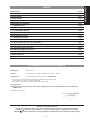
INDICE
1. DESCRIZIONE pag.2
2. CARATTERISTICHE TECNICHE pag.2
3. PREDISPOSIZIONI pag.2
4. LAY OUT SCHEDA pag.3
5. SCHEMA DI COLLEGAMENTO pag.3
6. DESCRIZIONE COLLEGAMENTI pag.3
6.1. MORSETTIERA CN1 pag.3
6.2. MORSETTIERA CN2 pag.4
6.3 COLLEGAMENTO MOTORE pag.5
6.4. KIT BATTERIE pag.5
7. REGOLAZIONE DIP-SWITCH pag.5
7.1. FUNZIONE ASTA APERTA pag.6
8. MEMORIZZAZIONE CODIFICA RADIO pag.6
8.1. Memorizzazione dei radiocomandi 868 MHz pag.6
8.2. Memorizzazione dei radiocomandi 433 MHz pag.7
8.3. Cancellazione dei codici radio pag.7
9. SENSIBILITÀ RILEVAMENTO OSTACOLO pag.7
10. PROGRAMMAZIONE pag.7
11. LED DI CONTROLLO pag.8
12. LOGICHE DI FUNZIONAMENTO pag.9
ITALIANO
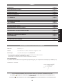
DICHIARAZIONE CE DI CONFORMITÁ
Note per la lettura dell’istruzione
Leggere completamente questo manuale di installazione prima di iniziare l’installazione del prodotto.
Il simbolo
evidenzia note importanti per la sicurezza delle persone e l’integrità dell’automazione.
Il simbolo
richiama l’attenzione su note riguardanti le caratteristiche od il funzionamento del prodotto.
Fabbricante: GENIUS S.p.A.
Indirizzo: Via Padre Elzi, 32 - 24050 - Grassobbio- Bergamo - ITALIA
Dichiara che: L’apparecchiatura elettronica mod. LYNX 05 24V
• è conforme ai requisiti essenziali di sicurezza delle seguenti direttive CEE:
73/23/CEE e successiva modifica 93/68/CEE.
89/336/CEE e successiva modifica 92/31/CEE e 93/68/CEE
Nota aggiuntiva:
Questo prodotto è stato sottoposto a test in una configurazione tipica omogenea (tutti prodotti di costruzione
GENIUS S.p.A.)
Grassobbio, 10-10-2007
L’Amministratore Delegato
D. Gianantoni

2
ITALIANO
APPARECCHIATURA ELETTRONICA LYNX 05
1. DESCRIZIONE
Questa centrale di comando per barriere automatiche a 24 Vdc, grazie all’elevata potenza del microprocessore di
cui è dotata, offre un ampio numero di regolazioni, con rallentamenti e controllo motore.
Grazie all’encoder integrato la centrale è in grado di controllare costantemente la posizione ed il movimento
dell’asta, intervenendo non appena viene rilevata una situazione anomala.
La presenza della funzione FOTOTEST permette rilevare eventuali anomalie nel funzionamento delle fotocellule.
Il settaggio dei principali modi di funzionamento e delle funzioni principali avviene tramite dip-switch, mentre la
regolazione dei tempi di lavoro e di pausa avviene in autoapprendimento durante la fase di programmazione.
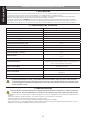
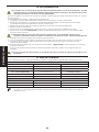
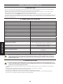
2. CARATTERISTICHE TECNICHE
Tensione di alimentazione 230 (+6% -10%) 50 Hz / 115 Vac 60 Hz
Tensione di alimentazione della centrale
24 Vac nominale 햲
Potenza assorbita 3 W
Potenza nominale motore 48 W
Carico max. accessori 500 mA
Carico max. lampeggiante 15 W
Carico max. luci su asta 15 W
Carico max. luce di cortesia / spia 5 W
Temperatura ambiente -20° +55°
Fusibile di protezione F1=8 A F2=500 mA F3=630 mA (ripristinabile)
Logiche di funzionamento Automatica - Condominiale - Manuale
Tempo di apertura / chiusura
In autoapprendimento durante la fase di programma-
zione
Tempo di pausa
In autoapprendimento durante la fase di programma-
zione
Rilevazione ostacolo Regolabile tramite trimmer
Funzioni selezionabili
Tipo di logica - Funzionamento del comando di open
- Funzione mancanza tensione di rete - Lampeggio luci
asta - Comportamento sicurezze
Ingressi in morsettiera
Alimentazione - Terra - Close - Open - Open/Close - Stop
- Sicurezze - Fototest
Ingressi con connettore Kit batterie - Connettore radio
Uscite in morsettiera
Alimentazione accessori - Luci su asta - Luce spia - Lam-
peggiante
Dimensioni scheda 79 x 158 mm
Caratteristiche batterie opzionali Vedi kit a listino
햲 In funzione della tensione di rete, sui morsetti di alimentazione della scheda, si possono avere dei valori
d’uscita diversi. Prima di procedere alla messa in servizio occorre verificare sempre che la tensione d’usci-
ta sull’avvolgimento secondario del trasformatore sia compresa tra i 20 Vac ed i 26 Vac. La tensione deve
essere misurata a vuoto.
3. PREDISPOSIZIONI
È importante per la sicurezza delle persone seguire attentamente tutte le avvertenze e le istruzioni presenti in
questo libretto. Un’errata installazione o un errato uso del prodotto può portare a gravi danni alle persone.
Verificare che a monte dell’impianto vi sia un adeguato interruttore differenziale come prescritto dalla normativa
vigente.
Prevedere, sulla rete d’alimentazione, un magnetotermico con interruzione onnipolare.
Verificare l’esistenza di un adeguato impianto di messa a terra.
Per la messa in opera dei cavi elettrici utilizzare adeguati tubi rigidi e/o flessibili.
Separare sempre i cavi di collegamento degli accessori a bassa tensione da quelli d’alimentazione 230/115 Vac
utilizzando, per evitare possibili interferenze, guaine separate.
•
•
•
•
•

3
ITALIANO
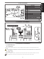
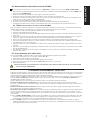
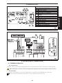
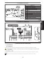
4. LAY OUT SCHEDA
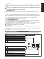
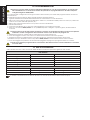
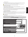
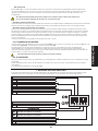
5. SCHEMA DI COLLEGAMENTO
6. DESCRIZIONE COLLEGAMENTI
6.1. MORSETTIERA CN1
6.1.1. ALIMENTAZIONE
Morsetti “1 & 2”. A questi morsetti devono essere collegati i fili dell’avvolgimento secondario del trasformatore
toroidale.
Prima di effettuare il collegamento controllare che la tensione in uscita dal trasformatore sia compresa tra i 20
Vac ed i 26 Vac
6.1.2. MESSA A TERRA
Morsetto “3”. Collegare a questo morsetto il filo di terra proveniente dal morsetto presente all’interno del corpo
motore.
Collegamento assolutamente necessario per il corretto funzionamento della centrale.
COMPONENTI
CN1 Morsettiera alimentazione
CN2 Morsettiera comandi
JP2 Connettore per kit batterie
JP3 Connettore per modulo ricevitore
JP4 Alimentazione motore chiusura DX
JP5 Alimentazione motore chiusura SX
TR1
Trimmer regolazione sensibilità rilevamento
ostacolo
P1 Pulsante di programmazione
P2 Pulsante memorizzazione canale OPEN
P3 Pulsante memorizzazione canale OPEN/CLOSE
F1 Fusibile di protezione scheda
DL1 Led contatto CLOSE
DL2 Led contatto OPEN
DL3 Led contatto OPEN/CLOSE
DL4 Led contatto STOP
DL5 Led stato fotocellule
DL6 Led segnalazione contatto OPEN
DL7 Led segnalazione contatto OPEN/CLOSE
Fig. 1Fig. 1
Fig. 2Fig. 2

4
ITALIANO
6.1.3. FOTOTEST
Morsetto “4”. Collegare a questo morsetto il morsetto negativo dei trasmettitori delle fotocellule. Eseguendo questo
collegamento la centrale effettua, prima di ogni manovra, un test sulle fotocellule controllandone il corretto fun-
zionamento. Se vengono utilizzate delle fotocellule il collegamento di questo morsetto è obbligatorio per il corretto
funzionamento della centrale.
6.1.4. ALIMENTAZIONE ACCESSORI
Morsetti “5 & 6”. Uscita 24 Vdc max. 500 mA per l’alimentazione degli accessori esterni.
• Il carico massimo di questa uscita è di 500 mA.
• Rispettare la polarità di alimentazione.
6.2. MORSETTIERA CN2
6.2.1. LUCI ASTA
Morsetti “7 & 10”. Uscita 24 Vdc max. 15 W. A questi morsetti vanno collegati i fili d’alimentazione del cordone lumi-
noso. Il funzionamento del cordone luminoso viene definito agendo sul dip-switch 5, vedi paragrafo 7.
Il morsetto “10” è l’uscita con polarità negativa.
6.2.2. LUCE SPIA
Morsetti “8 & 10”. Uscita 24 Vdc max 5 W. A questi morsetti deve essere collegata un’eventuale luce spia. La luce
spia permette di visualizzare lo stato dell’asta da una posizione remota, ad esempio una portineria, e precisamente:
La fase di apertura dell’asta è identificata da un lampeggio veloce.
Ad asta aperta la luce spia rimarrà accesa con luce fissa.
La fase di chiusura dell’asta è identificata da un lampeggio lento.
Ad asta chiusa la luce spia rimarrà spenta.
• A questa uscita è possibile collegare lampadine a 24 Vdc max. 5 W.
• Il morsetto “10” è l’uscita con polarità negativa.
6.2.3. LAMPEGGIANTE
Morsetti “9 & 10”. Uscita 24 Vdc max. 15 W. A questi morsetti viene collegato un lampeggiante a luce fissa, il
lampeggio è gestito dalla centrale. Il lampeggiante è attivo durante il movimento dell’asta mentre ad asta ferma,
aperta o chiusa, rimane spento. Prima della manovra di apertura dell’asta è stato inserito un prelampeggio di 0.5
sec. in modo da segnalare che l’asta sta per mettersi in movimento. Oltre a segnalare il movimento dell’asta il lam-
peggiante segnala, con una serie di lampeggi, l’alimentazione della sbarra tramite le batterie tampone (optional).
Il morsetto “10” è l’uscita con polarità negativa.
6.2.4. CLOSE
Morsetti “10 & 11”. Contatto normalmente aperto. Collegare tra questi due morsetti un qualsiasi datore d’impulso
(pulsante, selettore a chiave ecc..) che, chiudendo il contatto, deve comandare unicamente la chiusura dell’asta.
Lo stato di questo ingresso è segnalato dal led DL1.
• Il comando di CLOSE non è attivo durante la fase di programmazione.
• Più datori d’impulso devono essere collegati in parallelo.
6.2.5. OPEN
Morsetti “10 & 12”. Contatto normalmente aperto. Collegare tra questi due morsetti un qualsiasi datore d’impulso
(pulsante, selettore a chiave ecc..) che, chiudendo il contatto, deve comandare unicamente l’apertura dell’asta.
Lo stato di questo ingresso è segnalato dal led DL2.
• Il comando di OPEN non è attivo durante la fase di programmazione.
• Più datori d’impulso devono essere collegati in parallelo.
6.2.6. OPEN / CLOSE
Morsetti “10 & 13”. Contatto normalmente aperto. Collegare tra questi due morsetti un qualsiasi datore d’impulso
(pulsante, selettore a chiave ecc..) che, chiudendo il contatto, deve comandare un’apertura e/o una chiusura del-
l’asta. Il comportamento di questo ingresso è definito dal dip-switch 2, vedi paragrafo 7. Lo stato di questo ingresso
è segnalato dal led DL3.
• Più datori d’impulso devono essere collegati in parallelo.
6.2.7. STOP
Morsetti “10 & 14”. Contatto normalmente chiuso. Collegare tra questi due morsetti un qualsiasi datore d’impulso
(pulsante, selettore a chiave ecc..) che, aprendo il contatto, deve comandare l’arresto immediato dell’asta e la
disattivazione dell’eventuale richiusura automatica. Dopo l’attivazione di questo contatto, per riprendere il normale
ciclo programmato è necessario agire su un qualsiasi datore d’impulso che comandi l’apertura e/o la chiusura
dell’asta. Lo stato di questo ingresso è segnalato dal led DL4.
• Più datori d’impulso devono essere collegati in serie.
•
•
•
•

5
ITALIANO
6.2.8. SICUREZZE
Morsetti “10 & 15”. Contatto normalmente chiuso. Collegare a questi morsetti va collegato un qualsiasi dispositivo
di sicurezza (es. fotocellule) che, aprendo il contatto, agisce sul moto dell’asta. Queste possono essere attive solo
in chiusura oppure attive sia in chiusura che in apertura, a seconda di come viene posizionato il dip-switch 6, vedi
paragrafo 7.
•Se non vengono utilizzati dispositivi di sicurezza è necessario eseguire un collegamento tra il morsetto 4 ed il
morsetto 15.
• Più dispositivi di sicurezza devono essere collegati in serie.
Sicurezze attive in chiusura
Durante la fase di chiusura se vengono attivate le sicurezze la centrale inverte immediatamente il movimento
dell’asta sino alla completa apertura senza disabilitare, nel caso sia stata selezionata, la richiusura automatica
dell’asta.
Sicurezze attive in chiusura ed apertura:
In questo caso le sicurezze sono attive su entrambi i movimenti dell’asta. Durante la fase di chiusura se vengono
attivate le sicurezze la centrale inverte immediatamente il movimento dell’asta sino alla completa apertura senza
disabilitare, nel caso sia stata selezionata, la richiusura automatica dell’asta. Durante la fase d’apertura se vengono
attivate le sicurezze la centrale arresta immediatamente il movimento dell’asta e la mantiene ferma sino a quando
non viene ripristinata la sicurezza (ostacolo rimosso), solo allora riprenderà la manovra di apertura iniziata.
Lo stato di questo ingresso è segnalato dal led posto sotto il contatto.
6.3 COLLEGAMENTO MOTORE
L’automazione viene fornita predisposta per una chiusura destra, con il motore collegato al connettore JP4. Nel
caso di una chiusura sinistra è necessario collegare il motore al connettore JP5.
Il senso di chiusura dell’asta viene identificato guardando l’automazione dal lato del dispositivo di sblocco. Se per
effettuare la chiusura l’asta deve scendere a sinistra dell’automazione si avrà una chiusura sinistra, viceversa, se per
effettuare la chiusura l’asta deve scendere a destra dell’automazione, si avrà una chiusura destra.
Non è possibile collegare due motori alla stessa centrale.
6.4. KIT BATTERIE
È possibile collegare alla scheda un kit batterie, vedi listino, in modo da sopperire all’eventuale mancanza d’ali-
mentazione.
Per il corretto posizionamento del kit batterie all’interno del corpo motore fare riferimento alle istruzioni della parte
meccanica.
Il kit batterie deve essere collegato sull’apposito connettore JP2.
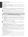
7. REGOLAZIONE DIP-SWITCH
Sulla centrale sono presenti 6 dip-switch che consentono di determinare il comportamento dell automazione e
delle sicurezze ad essa collegate. Nello schema seguente è stato riepilogato il comportamento di ogni singolo
dip-switch:
CHIUSURA AUTOMATICA
ON Chiusura automatica attivata
OFF Chiusura automatica disattivata
CHIUSURA AUTOMATICA
ON Chiusura automatica attivata
OFF Chiusura automatica disattivata
COMPORTAMENTO INGRESSO OPEN/CLOSE
ON Apre / Stop / Chiude / Stop ...
OFF Apre / Chiude / Apre .....
COMPORTAMENTO INGRESSO OPEN/CLOSE
ON Apre / Stop / Chiude / Stop ...
OFF Apre / Chiude / Apre .....
ASTA APERTA (vedi paragrafo 7.1)
ON Funzione asta aperta attiva
OFF Funzione asta aperta disattivata
ASTA APERTA (vedi paragrafo 7.1)
ON Funzione asta aperta attiva
OFF Funzione asta aperta disattivata
LOGICA CONDOMINIALE
ON Logica condiminiale attiva
OFF Logica condominiale disattivata
LOGICA CONDOMINIALE
ON Logica condiminiale attiva
OFF Logica condominiale disattivata
LUCE ASTA
ON
Luce asta accesa con asta aperta e chiusa, lampeg-
giante con asta in movimento
OFF
Luce asta spenta con asta aperta e chiusa, lampeggian-
te con asta in movimento.
LUCE ASTA
ON
Luce asta accesa con asta aperta e chiusa, lampeg-
giante con asta in movimento
OFF
Luce asta spenta con asta aperta e chiusa, lampeggian-
te con asta in movimento.
FOTOCELLULE
ON Fotocellule attiva sia in chiusura che in apertura
OFF Fotocellule attive solo in chiusura
FOTOCELLULE
ON Fotocellule attiva sia in chiusura che in apertura
OFF Fotocellule attive solo in chiusura

6
ITALIANO
7.1. FUNZIONE ASTA APERTA
Con questa funzione, in abbinamento o meno al kit batterie, si possono avere i seguenti comportamenti della
sbarra:
SENZA KIT BATTERIE
Dip-switch 4=OFF: In caso di mancanza dell’alimentazione di rete la sbarra rimane ferma nella posizione in cui si
trova. Al ripristino della tensione di rete, dopo 2 secondi la centrale comanda in automatico una chiusura della
sbarra predisponendosi per il normale funzionamento.
Dip-switch 4=ON: In caso di mancanza dell’alimentazione di rete la sbarra rimane ferma nella posizione in cui si tro-
va. Al ripristino della tensione di rete è necessario inviare un impulso per far si che la centrale riprenda il normale
funzionamento.
CON KIT BATTERIE
Dip-switch 4=OFF: In caso di mancanza dell’alimentazione di rete la sbarra continua a funzionare normalmente. Ad
ogni apertura il lampeggiante effettuerà due lampeggi consecutivi con intervalli di 3 secondi l’uno dall’altro,
per un tempo massimo di 30 secondi, segnalando che la sbarra è alimentata tramite batterie. Al ripristino della
tensione di rete l’automazione riprende il normale funzionamento.
Il numero di cicli possibili con l’automazione alimentata a batterie è influenzato dal livello di carica delle
batterie, dal tempo trascorsa dalla sospensione dell’alimentazione di rete, dalle condizioni dell’automazio-
ne, dalla temperatura esterna etc...
Dip-switch 4=ON: In caso di mancanza dell’alimentazione di rete l’automazione esegue, in modo automatico,
un’apertura arrestando l’asta in posizione verticale e disattivando tutti i comandi. Al ripristino della tensione di
rete, se è stata selezionata una logica automatica, l’automazione esegue in automatico una manovra di chiu-
sura predisponendosi per il normale funzionamento. Viceversa con la logica manuale l’automazione attende un
impulso per riprendere il normale funzionamento.
8. MEMORIZZAZIONE CODIFICA RADIO
La centrale di comando è provvista di un sistema di decodifica bi-canale integrato. Questo sistema permette di
memorizzare, tramite il modulo ricevitore, sia il comando di OPEN che il comando OPEN/CLOSE.
Il sistema di decodifica permette di memorizzare sia i radiocomandi con frequenza 868 MHz che i radiocomandi
con frequenza 433 MHZ.
• È possibile utilizzare una sola codifica radio per volta. Per passare da una codifica all’altra è necessario
cancellare la codifica radio esistente (vedi paragrafo 8.3), sostituire il modulo ricevitore e ripetere le fasi di
programmazione.
• L’inserimento e l’eventuale rimozione del modulo ricevitore deve avvenire solo dopo aver tolto tensione alla
scheda.
• Il modulo ricevitore può essere inserito solo in una posizione. Orientare correttamente il modulo senza eser-
citare forzature.
8.1. Memorizzazione dei radiocomandi 868 MHz
È possibile memorizzare fino ad un massimo di 250 codici, suddivisi tra i due canali, OPEN e OPEN/CLOSE.
Sul radiocomando premere e tenere premuti i pulsanti P1 e P2 contemporaneamente (vedi istruzioni radioco-
mando).
Dopo circa un secondo il led del radiocomando inizia a lampeggiare.
Lasciare entrambi i pulsanti.
Premere e tenere premuto sulla scheda il pulsante P2 o P3 per memorizzare rispettivamente il canale di OPEN o
OPEN/CLOSE. Il led relativo inizia a lampeggiare.
Premere contemporaneamente il pulsante del radiocomando al quale si vuole abbinare il comando scelto.
Verificare che il led relativo al comando che si sta memorizzando (DL6 per il canale di OPEN o DL7 per il canale
di OPEN/CLOSE) si accenda a luce fissa per un paio di secondi a conferma della corretta memorizzazione.
Per terminare la programmazione è necessario premere per due volte, in breve successione, il pulsante del
radiocomando memorizzato.
L’automazione effettuerà una manovra d’apertura, assicurarsi che non vi siano ostacoli nel raggio d’azione.
Per memorizzare l’altro canale è necessario ripetere tutta la procedura dal punto 1.
Per aggiungere altri radiocomandi è necessario trasferire il codice del pulsante del radiocomando memorizzato al
pulsante corrispondente dei radiocomandi da aggiungere, ripetendo la procedura di memorizzazione o seguendo
la seguente procedura:
Sul radiocomando memorizzato premere contemporaneamente i pulsanti P1 e P2 (vedi istruzioni radiocomando)
e tenerli premuti.
Il led del radiocomando inizia a lampeggiare.
Lasciare entrambi i pulsanti.
Accostare frontalmente a contatto i due radiocomandi.
Sul radiocomando memorizzato premere e tenere premuto il pulsante relativo al canale che si vuole trasferire, il
led del radiocomando si accende a luce fissa.
Sul radiocomando da memorizzare premere il pulsante desiderato e rilasciarlo dopo che il radiocomando ha
effettuato un doppio lampeggio.
Per terminare la programmazione è necessario premere per due volte, in breve successione, il pulsante del radio-
comando memorizzato.
L’automazione effettuerà una manovra d’apertura, assicurarsi che non vi siano ostacoli nel raggio d’azione.
1.
2.
3.
4.
5.
6.
7.
8.
•
•
•
•
•
•
•

7
ITALIANO
8.2. Memorizzazione dei radiocomandi 433 MHz
È possibile memorizzare fino ad un massimo di 250 codici, suddivisi tra i due canali, OPEN e OPEN/CLOSE.
Premere sulla centrale il pulsante relativo al canale che si desidera memorizzare, P2 per il canale di OPEN o P3
per il canale di OPEN/CLOSE.
Il relativo led sulla centrale inizia a lampeggiare, rilasciare il pulsante.
Sul radiocomando premere il pulsante al quale si vuole associare al canale scelto.
Il led sulla centrale si accende a luce fissa per circa un secondo, segnalando l’avvenuta memorizzazione del
radiocomando, per poi riprendere a lampeggiare.
In questa fase è possibile memorizzare ulteriori radiocomandi.
Trascorsi circa 10 secondi la centrale esce automaticamente dalla fase di apprendimento.
Per aggiungere altri radiocomandi o memorizzare il secondo canale ripetere le operazioni dal punto 1
8.2.1. MEMORIZZAZIONE REMOTA DEI RADIOCOMANDI 433 MHZ
Solo con radiocomandi 433 si possono memorizzare altri radiocomandi, in modo remoto, cioè senza intervenire sui
pulsanti della centrale, ma utilizzando un radiocomando precedentemente memorizzato.
Procurarsi un radiocomando già memorizzato su uno dei 2 canali.
Portarsi in prossimità dell’automazione.
Premere e tenere premuti i pulsanti P1 e P2 (vedi istruzioni del radiocomando) contemporaneamente per circa
5 secondi.
Entro 5 secondi premere sul radiocomando memorizzato il pulsante che si desidera trasferire al nuovo radioco-
mando. In questo modo sulla centrale si attiva la fase di apprendimento sul canale selezionato.
Entro 5 secondi premere sul nuovo radiocomando il pulsante che si desidera associare al canale scelto.
Dopo la memorizzazione del nuovo radiocomando, la centrale mantiene attiva la modalità di apprendimento
sul canale scelto per circa 5 secondi.
Durante questi 5 secondi è possibile memorizzare sulla centrale altri radiocomandi, sempre abbinati al canale
attivato.
Trascorsi 5 secondi dalla memorizzazione dell’ultimo radiocomando la centrale esce in modo automatico dalla
fase di apprendimento.
Per verificare se il radiocomando è stato memorizzato in modo corretto è necessario attendere 5 secondi
dall’invio del codice.
8.3. Cancellazione dei codici radio
Per cancellare tutti i codici dei radiocomandi memorizzati seguire la seguente procedura:
Premere e tenere premuto uno dei due pulsanti P2 o P3.
Il led corrispondente inizia a lampeggiare.
Trascorsi cinque secondi il led inizia a lampeggiare velocemente.
Dopo altri cinque secondi entrambi i led, DL6 e DL7 si accendono a luce fissa.
Rilasciare il pulsante.
Questa operazione non è reversibile e si cancelleranno tutti i radiocomandi associati sia al comando OPEN
che al comando OPEN/CLOSE.
9. SENSIBILITÀ RILEVAMENTO OSTACOLO
Il dispositivo di rilevamento ostacolo permette alla centrale di rilevare eventuali ostacoli durante la movimentazione
dell’asta. Questo dispositivo, essendo di tipo elettronico, rimane costante nel tempo e non è soggetto a variazione,
questo garantisce un livello di sicurezza costante dell’automazione.
Agendo sul trimmer TR1 è possibile aumentare o diminuire la sensibilità di rilevamento ostacolo. Ruotando il trimmer
in senso orario si aumenta la sensibilità di rilevamento, viceversa ruotandolo in senso antiorario si diminuisce la
sensibilità di rilevamento ostacolo.
Questo dispositivo è attivo sia durante la fase di chiusura che in fase di apertura dell’asta.
Se interviene durante la fase di apertura blocca il funzionamento dell’automazione ed inverte il moto per 1
secondo. A questo punto è necessario inviare alla centrale un impulso per far riprendere il normale funzionamento
programmato.
Se interviene durante la fase di chiusura inverte il funzionamento sino alla completa apertura dell’automazione
senza disattivare l’eventuale chiusura automatica.
Se interviene per tre volte consecutive blocca il funzionamento dell’automazione e si posiziona in stop disattivando,
nel caso sia stata attivata, la chiusura automatica. Per ripristinare il normale funzionamento è necessario coman-
dare un’apertura o una chiusura della sbarra. A seconda del comando che viene inviato si avranno dei comporta-
menti diversi:
Impulso di OPEN o OPEN/CLOSE: In questo caso l’asta inizierà una manovra di apertura in modo rallentato sino alla
completa apertura della sbarra. Una volta raggiunta la completa apertura l’asta riprende il normale ciclo di
funzionamento riattivando, nel caso sia stata abilitata la richiusura automatica.
Impulso di CLOSE: In questo caso l’asta inizierà una manovra di chiusura in modo rallentato sino alla completa
chiusura della sbarra. Una volta chiusa l’asta riprende il normale ciclo di funzionamento riattivando, nel caso sia
stata abilitata la richiusura automatica.
1.
2.
3.
4.
5.
6.
7.
1.
2.
3.
4.
5.
6.
7.
8.
9.
1.
2.
3.
4.
5.

8
ITALIANO
10. PROGRAMMAZIONE
Alla prima accensione della centrale è obbligatorio effettuare un ciclo di programmazione. La scheda man-
tiene disabilitati tutti i comandi ad eccezione del pulsante P1 di programmazione e dei datori d’impulso
collegati all’ingresso OPEN/CLOSE
Una volta eseguiti i collegamenti di tutti gli accessori e datori si deve procedere alla programmazione del ciclo di
funzionamento.
Per eseguire la programmazione della centrale seguire le seguenti istruzioni:
Agendo sull’interruttore differenziale assicurarsi che l’automazione non sia alimentata.
Sbloccare l’automazione agendo sul dispositivo di sblocco, vedi istruzioni della parte meccanica, e posizionare
l’asta a circa metà della sua apertura (45°).
Ribloccare l’asta ed assicurarsi che non possa muovere manualmente.
Alimentare il sistema.
Premere il tasto P1 per circa 1 secondo, il lampeggiante si accenderà a luce fissa.
Dare un comando di OPEN/CLOSE con un qualsiasi dispositivo collegato a questo ingresso, la sbarra inizia a
muoversi.
La prima manovra che la sbarra deve eseguire è in chiusura. Se l’automazione inizia una manovra di apertura
verificare il corretto collegamento del connettore motore come descritto nel paragrafo 6.3.
Ripristinare la tensione d’alimentazione e ripetere la procedura dal punto 5.
Una volta raggiunto il fermo meccanico in chiusura l’asta inizia la manovra d’apertura.
Raggiunta l’apertura massima inizia il conteggio del tempo di pausa per la richiusura automatica.
Trascorso il tempo desiderato dare un impulso di OPEN/CLOSE e l’automazione inizia la fase di chiusura.
Una volta raggiunta la posizione di chiusura il lampeggiante si spegne e la programmazione e conclusa.
Durante la procedura di programmazione il movimento della sbarra avviene in modo rallentato e le sicurezze
non sono attive.
11. LED DI CONTROLLO
Sulla centrale si trovano 7 led di controllo. Nella tabella sottostante è riportato il significato dei vari led:
LEDS INGRESSI
LED ACCESO SPENTO
DL1 - Ingresso CLOSE Comando attivo Comando inattivo
DL2 - ingresso OPEN Comando attivo Comando inattivo
DL3 - ingresso OPEN/CLOSE Comando attivo Comando inattivo
DL4 - ingresso STOP Comando inattivo Comando attivo
DL5 - ingresso FSW Sicurezze libere Sicurezze impegnate
LED PROGRAMMAZIONE
LED ACCESO SPENTO
DL6 - canale OPEN Ingresso attivo Ingresso inattivo
DL7 - canale OPEN/CLOSE Ingresso attivo Ingresso inattivo
In neretto è evidenziata la condizione dei leds con centrale alimentata e sbarra chiusa a riposo.
1.
2.
3.
4.
5.
6.
7.
8.
9.
10.
11.

9
ITALIANO
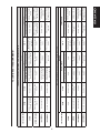
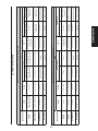
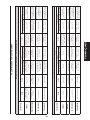
12. LOGICHE DI FUNZIONAMENTO
LOGICA A (Automatica) DIP-SWITCH 1=ON / DIP-SWITCH 3=OFF
STATO BARRIERA
INGRESSI
OPEN CLOSE
OPEN / CLOSE
STOP
FOTOCELLULE
DIP-SWITCH 2=ON DIP-SWITCH 2=OFF DIP-SWITCH 6=OFF DIP-SWITCH 6=ON
CHIUSA
Apre e richiude dopo
il tempo di pausa
Nessun effetto
Apre e richiude dopo
il tempo di pausa
Apre e richiude dopo
il tempo di pausa
Nessun effetto (se
attivo inibisce tutti i
comandi)
Nessun effetto
Inibisce i comandi di
OPEN
APERTA IN PAUSA
Ricalcola il tempo di
pausa
Chiude immediata-
mente
Blocca il funziona-
mento
Richiude immediata-
mente
Blocca il funziona-
mento
Inibisce i comandi, al
disimpegno ripristina il
tempo di pausa
Inibisce i comandi, al
disimpegno ripristina il
tempo di pausa
IN APERTURA Nessun effetto Chiude
Blocca il funziona-
mento, al successivo
impulso chiude
Inverte il moto in
chiusura
Blocca il funziona-
mento
Nessun effetto
Blocca il movimento
ed al disimpegno
riprende
IN CHIUSURA Inverte in apertura Nessun effetto
Blocca il funziona-
mento, al successivo
impulso apre
Inverte il moto in
apertura
Blocca il funziona-
mento
Inverte il moto in
apertura
Blocca il movimento,
al disimpegno apre
LOGICA M (Manuale) DIP-SWITCH 1=OFF / DIP-SWITCH 3=OFF
STATO BARRIERA
INGRESSI
OPEN CLOSE
OPEN / CLOSE
STOP
FOTOCELLULE
DIP-SWITCH 2=ON DIP-SWITCH 2=OFF DIP-SWITCH 6=OFF DIP-SWITCH 6=ON
CHIUSA Apre Nessun effetto Apre Apre
Nessun effetto (se
attivo inibisce tutti i
comandi)
Nessun effetto
Inibisce i comandi di
OPEN
APERTA Nessun effetto
Chiude immediata-
mente
Richiude immediata-
mente
Richiude immediata-
mente
Blocca il funziona-
mento
Inibisce tutti i co-
mandi
Inibisce i comandi
IN APERTURA Nessun effetto Chiude
Blocca il funziona-
mento
Inverte il moto in
chiusura
Blocca il funziona-
mento
Nessun effetto
Blocca il movimento
ed al disimpegno
riprende
IN CHIUSURA Inverte in apertura Nessun effetto
Blocca il funziona-
mento
Inverte il moto in
apertura
Blocca il funziona-
mento
Inverte il moto in
apertura
Blocca il movimento,
al disimpegno apre

10
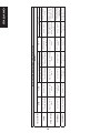
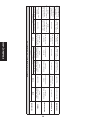
ITALIANO
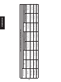
LOGICA C (Condominiale) DIP-SWITCH 1=ON / DIP-SWITCH 3=ON
STATO BARRIERA
INGRESSI
OPEN CLOSE
OPEN / CLOSE
STOP
FOTOCELLULE
DIP-SWITCH 2=ON DIP-SWITCH 2=OFF DIP-SWITCH 6=OFF DIP-SWITCH 6=ON
CHIUSA
Apre e richiude dopo
il tempo di pausa
Nessun effetto
Apre e richiude dopo
il tempo di pausa
Apre e richiude dopo
il tempo di pausa
Nessun effetto (se
attivo inibisce tutti i
comandi)
Nessun effetto
Inibisce i comandi di
OPEN
APERTA IN PAUSA
Ricalcola il tempo di
pausa
Chiude immediata-
mente
Ricalcola il tempo di
pausa
Richiude immediata-
mente
Blocca il funziona-
mento
Inibisce i comandi
ed al disimpegno
ricarica il tempo di
pausa
Inibisce i comandi ed
al disimpegno ricarica
il tempo di pausa
IN APERTURA Nessun effetto
Inverte il moto in
chiusura
Nessun effetto Nessun effetto
Blocca il funziona-
mento
Nessun effetto
Blocca il movimento
ed al disimpegno
riprende
IN CHIUSURA Inverte in apertura Nessun effetto
Inverte il moto in
apertura
Inverte il moto in
apertura
Blocca il funziona-
mento
Inverte il moto in
apertura
Blocca il movimento,
al disimpegno apre

11
INDEX
1. DESCRIPTION page.12
2. TECHNICAL SPECIFICATIONS page.12
3. PREPARATIONS page.12
4. BOARD LAY-OUT page.13
5. CONNECTION LAY-OUT page.13
6. DESCRIPTION OF CONNECTIONS page.13
6.1. TERMINAL BOARD CN1 page.13
6.2. TERMINAL BOARD CN2 page.14
6.3 MOTOR CONNECTION page.15
6.4. BATTERY KIT page.15
7. DIP-SWITCH ADJUSTMENT page.15
7.1. OPEN BEAM FUNCTION page.16
8. MEMORY STORING THE RADIO CODE page.16
8.1. Memory storage of 868 MHz radio controls page.16
8.2. Memory storage of 433 MHz radio controls page.17
8.3. Deletion of radio codes page.17
9. OBSTACLE DETECTION SENSITIVITY page.17
10. PROGRAMMING page.18
11. CONTROL LEDs page.18
12. FUNCTION LOGICS page.19
ENGLISH
CE DECLARATION OF CONFORMITY
Notes on reading the instruction
Read this installation manual to the full before you begin installing the product.
The symbol
indicates notes that are important for the safety of persons and for the good condition of the
automated system.
The symbol
draws your attention to the notes on the characteristics and operation of the product.
Manufacturer: GENIUS S.p.A.
Address: Via Padre Elzi, 32 - 24050 - Grassobbio- Bergamo - ITALY
Declares that: Control unit mod. LYNX 05 24V
• conforms to the essential safety requirements of the following EEC directives:
73/23/EEC and subsequent amendment 93/68/EEC.
89/336/EEC and subsequent amendment 92/31/EEC and 93/68/EEC
Additional information:
This product underwent a test in a typical uniform configuration (all products manufactured by GENIUS S.p.A.).
Grassobbio, 10-10-2007
Managing Director
D. Gianantoni

12
ENGLISH
CONTROL UNIT LYNX 05
1. DESCRIPTION
Thanks to its high powered microprocessor, this 24 Vdc control unit for automatic barriers offers a wide range of
adjustments, including deceleration and motor control.
Thanks to its integrated encoder, the control unit constantly controls rod position and movement, intervening as
soon as a faulty situation is detected.
The FOTOTEST function makes it possible to detect any faults in the operation of the photocells.
The main operating modes and functions are set by a dip-switch, whereas the adjustment of work and pause times
is done by self learning during programming.
2. TECHNICAL SPECIFICATIONS
Power supply voltage 230 (+6% -10%) 50 Hz / 115 Vac 60 Hz
Supply voltage of control unit
24 Vac nominal 햲
Absorbed power 3 W
Motor nominal power 48 W
Accessories max. load 500 mA
Flashing lamp max. load 15 W
Max. load for beam lights 15 W
Max. load for courtesy light/indicator light 5 W
Operating ambient temperature -20° +55°
Protective fuse F1=8 A F2=500 mA F3=630 mA (resettable)
Function logics Automatic - Condo - Manual
Opening / closing time Through self-learning during programming
Pause time Through self-learning during programming
Obstacle detection Trimmer-adjustable
Selectable functions
Type of logic - Operation of open command - No mains
power supplied function - Beam lights flashing - Safety
devices behaviour
Terminal board inputs
Power supply - Earth - Close - Open - Open/Close - Stop
- Safety devices - Fototest
Inputs with connector Battery kit - Radio connector
Terminal board outputs
Power supply for accessories - On beam lights - Indicator
light - Flashlight
Board dimensions 79 x 158 mm
Characteristics of optional batteries See kit on price list
햲 According to mains voltage, there may be different output values on the board power feed terminals.
Before putting into service, always check if the output voltage on the secondary winding of the transformer
is from 20 Vac to 26 Vac. Voltage must always be measured load free.
3. PREPARATIONS
To ensure people’s safety, all warnings and instructions in this booklet must be carefully observed. Incorrect
installation or incorrect use of the product could cause serious harm to people.
Make sure that an adequate differential switch is installed upstream of the system as specified by current
regulations.
On the main power supply, install a thermal breaker with omnipolar switching.
Make sure that an adequate earthing system is available.
To lay cables, use adequate rigid and/or flexible tubes.
Always separate the connecting cables of low voltage accessories from those supplying 230/115 Vac, using
separate sheaths to avoid possible interference.
•
•
•
•
•

13
ENGLISH
4. BOARD LAY-OUT
5. CONNECTION LAY-OUT
6. DESCRIPTION OF CONNECTIONS
6.1. TERMINAL BOARD CN1
6.1.1. POWER SUPPLY
Terminals “1 & 2”. The secondary winding wires of the toroidal transformer must be connected to these terminals.
Before making this connection, check if the voltage at the transformer output is in the range from 20 Vac to 26 Vac
6.1.2. EARTHING
Terminal “3”. To this terminal, connect the earthing wire coming from the terminal inside the motor body.
The connection is absolutely necessary for correct operation of the control unit.
COMPONENTS
CN1 Power supply terminal-board
CN2 Commands terminal-board
JP2 Battery kit connector
JP3 Connector for receiver module
JP4 Power supply to RH closing motor
JP5 Power supply to LH closing motor
TR1
Trimmer for adjusting obstacle detection
sensitivity
P1 Programming push-button
P2 OPEN channel memory storage push-button
P3
OPEN/CLOSE channel memory storage push-button
F1 Board protection fuse
DL1 CLOSE contact LED
DL2 OPEN contact LED
DL3 OPEN/CLOSE contact LED
DL4 STOP contact LED
DL5 Photocells status LED
DL6 OPEN contact signalling LED
DL7 OPEN/CLOSE contact signalling LED
Fig. 1Fig. 1
Fig. 2Fig. 2

14
ENGLISH
6.1.3. FOTOTEST
Terminal “4 ”. Connect to this terminal, the negative terminal of the photocell transmitters. By making this
connection, the control unit, before every manoeuvre, runs a test on the photocells, controlling correct operation.
If you use photocells, this terminal must be connected to ensure the control unit operates correctly.
6.1.4. POWER SUPPLY FOR ACCESSORIES
Terminals “5 & 6”. 24 Vdc output max. 500 mA for feeding the external accessories.
• Maximum load of this output is 500 mA.
• Observe the power supply polarity.
6.2. TERMINAL BOARD CN2
6.2.1. BEAM LIGHTS
Terminals “7 & 10”. Output 24 Vdc max.15 W. The wires feeding the luminous strip should be connected to these
terminals. The operation of the luminous strip is defined by using dip-switch 5 - see paragraph 7.
Terminal “10” is the negative polarity output.
6.2.2. INDICATOR LIGHT
Terminals “8 & 10”. Output 24 Vdc max. 5 W. An indicator light, if any, should be connected to these terminals. The
indicator light makes it possible to see the beam status from a remote position, e.g. a porter’s lodge - details:
Beam opening is identified by fast flashing.
When the beam is open, the indicator light stays lighted on a steady light-beam.
Beam closing is identified by slow flashing.
When the beam is closed, the indicator light stays OFF.
• 24 Vdc max. 5 W lamps can be connected to this output.
• Terminal “10” is the negative polarity output.
6.2.3. FLASHING LIGHT
Terminals “9 & 10”. Output 24 Vdc max.15 W. A steady beam flashing light is connected to these terminals - flashing
is controlled by the control unit. The flashing light is active while the beam is moving, whereas when the beam is idle,
whether open or closed, it stays OFF. Pre-flashing of 0.5 sec was inserted before the beam opening manoeuvre, to
signal that the beam is about to move. In addition to signalling beam movement, the flashing light signals - by a
series of flashes - that the beam is being powered by the buffer battery (optional).
Terminal “10” is the negative polarity output.
6.2.4. CLOSE
Terminals “10 & 11”. Normally open contact. Connect, between these 2 terminals, any pulse generator (e.g.
push-button, key selector, etc..) which, by closing the contact, commands beam closure only. The status of this
input is signalled by LED “DL1”.
• The CLOSE command is not active during programming.
• If there are several pulse generators, they must be connected in parallel.
6.2.5. OPEN
Terminals “10 & 12”. Normally open contact. Connect, between these 2 terminals, any pulse generator (e.g.
push-button, key selector, etc..) which, by closing the contact, commands beam opening only. The status of this
input is signalled by LED “DL2”.
• The OPEN command is not active during programming.
• If there are several pulse generators, they must be connected in parallel.
6.2.6. OPEN / CLOSE
Terminals “10 & 13”. Normally open contact. Connect, between these 2 terminals, any pulse generator (e.g.
push-button, key selector, etc..) which, by closing the contact, commands beam opening and/or closing. The
behaviour of this input is defined by dip-switch 2, see paragraph 7. The status of this input is signalled by LED “DL3”.
• If there are several pulse generators, they must be connected in parallel.
6.2.7. STOP
Terminals “10 & 14”. Normally closed contact. Connect, between these 2 terminals, any pulse generator (e.g.
push-button, key selector, etc..) which, by opening the contact, must command immediate stop of the beam and
the de-activation of any automatic re-closure. To resume the normal programmed cycle after this contact has been
activated, use any pulse generator which commands the opening and/or closing of the beam. The status of this
input is signalled by LED “DL4”.
• If there are several pulse generators, they must be connected in series.
•
•
•
•

15
ENGLISH
6.2.8. SAFETY DEVICES
Terminals “10 & 15”. Normally closed contact. Connect, to these terminals, any safety device (e.g. photocells)
which, by opening the contact, acts on beam motion. They can be active only during closure, or active in both
closing and opening, according to the position of dip-switch 6, see paragraph 7.
•If the safety devices are not used, a connection must be made between terminal 4 and terminal 15.
• If there are several safety devices, they must be connected in series.
Safety devices active at closure
If the safety devices are activated during closure, the control unit immediately reverses beam movement until
opening is complete without disabling - if selected - automatic re-closing of the beam.
Safety devices active at closure and opening:
In this case the safety devices are active on both beam movements. If the safety devices are activated during
closure, the control unit immediately reverses beam movement until opening is complete without disabling - if
selected - automatic re-closing of the beam. If the safety devices are activated during opening, the control unit
immediately stops beam movement and keeps it stopped until the safety device is reset (obstacle removed), and
only then will the opening manoeuvre which had been started be resumed.
The status of this input is signalled by the LED located under the contact.
6.3 MOTOR CONNECTION
The automated system is supplied designed for right hand closure, with the motor connected to connector JP4. For
left hand closure, the motor must be connected to connector JP5.
To identify beam closing direction, look at the automated system from the side of the release device. If the beam
has to descend on the left of the automated system in order to close, left hand closure is involved, vice-versa, if the
beam has to descend on the right of the automated system in order to close, right hand closure is involved.
Two motors cannot be connected to the same control unit.
6.4. BATTERY KIT
A battery kit can be connected to the board - see price list - to make up for a possible power cut.
For correct positioning of the battery kit inside the motor body, refer to the instruction for the mechanical part.
The battery kit must be connected to connector JP2.
7. DIP-SWITCH ADJUSTMENT
6 dip-switches are located on the control unit. They command the behaviour of the automated system and of the
safety devices connected to it. The behaviour of every dip-switch is summarised on the following table:
AUTOMATIC CLOSING
ON Automatic closing activated
OFF Automatic closing disabled
AUTOMATIC CLOSING
ON Automatic closing activated
OFF Automatic closing disabled
OPEN/CLOSE INPUT BEHAVIOUR
ON Open / Stop / Close / Stop ...
OFF Open / Close / Open .....
OPEN/CLOSE INPUT BEHAVIOUR
ON Open / Stop / Close / Stop ...
OFF Open / Close / Open .....
OPEN BEAM (see paragraph 7.1)
ON Open beam function activated
OFF Open beam function disabled
OPEN BEAM (see paragraph 7.1)
ON Open beam function activated
OFF Open beam function disabled
CONDO LOGIC
ON Condo logic activated
OFF Condo logic disabled
CONDO LOGIC
ON Condo logic activated
OFF Condo logic disabled
BEAM LIGHT
ON
Beam light ON when beam open and closed, flashing
while beam is moving.
OFF
Beam light OFF when beam open and closed, flashing
while beam is moving.
BEAM LIGHT
ON
Beam light ON when beam open and closed, flashing
while beam is moving.
OFF
Beam light OFF when beam open and closed, flashing
while beam is moving.
PHOTOCELLS
ON Photocells ON both during closing and opening
OFF Photocells ON during closing only
PHOTOCELLS
ON Photocells ON both during closing and opening
OFF Photocells ON during closing only

16
ENGLISH
7.1. OPEN BEAM FUNCTION
With this function, combined or not with the battery kit, the following beam behaviour patterns are possible:
WITHOUT BATTERY KIT
Dip-switch 4=OFF: If there is a mains power cut, the beam stays stopped in the position it is in. When mains power
returns, after 2 seconds the control unit automatically commands the beam to close, preparing itself for normal
operation.
Dip-switch 4=ON: If there is a mains power cut, the beam stays stopped in the position it is in. When mains power
returns, a pulse must be sent to ensure that the control unit resumes normal operation.
WITH BATTERY KIT
Dip-switch 4=OFF: If there is a mains power cut, the beam continues operating normally. At every opening, the
flashing light flashes twice consecutively, at intervals of 3 seconds between the flashes, for a maximum time of
30 seconds, signalling that the beam is battery powered. When mains power is resumed, the automated system
resumes normal operation.
The number of cycles possible with the automated system battery powered, depends on the battery
charge level, on the time elapsing since mains power was stopped, and on the conditions of the
automated system, external temperature etc...
Dip-switch 4=ON: In the event of a mains power cut, the automated system automatically opens the beam,
stopping it in vertical position and disabling all the commands. When mains power returns, if automatic logic
was selected, the automated system automatically performs a closing movement preparing itself for normal
operation. Vice-versa, if manual logic was selected, the automated system waits for a pulse to resume normal
operation.
8. MEMORY STORING THE RADIO CODE
The control unit has an integrated 2-channel decoding system. The system makes it possible to memory store - via
the receiver module - both the OPEN command and the OPEN/CLOSE command.
The decoding system makes it possible to memory store both the commands with a frequency of 868 MHz and the
commands with a frequency of 433 MHz.
• Only one radio code can be used at a time. To change over from one code to the other, delete the existing
radio code (see paragraph 8.3), replace the receiver module and repeat the programming stages.
• Fitting and, if necessary, removing the receiver module must be done only after cutting power to the board.
• The receiver module can only be inserted in one position. Orient the module correctly without forcing.
8.1. Memory storage of 868 MHz radio controls
You can memory store up to a maximum of 250 codes, subdivided between the two channels, OPEN and
OPEN/CLOSE.
On the radio control, simultaneously press and hold down push-buttons P1 and P2 (see radio control instructions).
After about one second, the LED of the radio control begins to flash.
Release both push-buttons.
Press and hold down push-button P2 or P3 on the board to respectfully memory store the OPEN or OPEN/CLOSE
channel. The relevant LED begins to flash.
Simultaneously press the push-button of the radio control with which you wish to associate the selected
command.
Check if the LED relating to the command being memory stored (DL6 for the OPEN channel or DL7 for the OPEN/
CLOSE channel) lights up on steady beam for about two seconds to confirm correct memory storage.
To finish programming, press twice in close succession, the push-button of the memory stored radio control.
The automated system will perform an opening manoeuvre - make sure that there are no obstacles inside the
operating range.
To memory store the other channel, repeat all the procedure from point 1.
To add other radio controls, transfer the code of the memory-stored push-button of the radio control to the relevant
push-button of the radio controls to be added, repeating the memory storage procedure or observing the following
procedure:
On the memory stored radio control, simultaneously press and hold down push-buttons P1 and P2 (see radio
control instructions).
The radio control LED begins to flash.
Release both push-buttons.
Put the two radio controls frontally into contact.
On the memory stored radio control, press and hold down the push-button relating to the channel you wish to
transfer - the radio control LED lights up on steady beam.
On the radio control to be memory stored, press the required push-button and release it after the radio control has
flashed twice.
To finish programming, press twice in close succession, the push-button of the memory stored radio control.
The automated system will perform an opening manoeuvre - make sure that there are no obstacles inside the
operating range.
1.
2.
3.
4.
5.
6.
7.
8.
•
•
•
•
•
•
•

17
ENGLISH
8.2. Memory storage of 433 MHz radio controls
You can memory store up to a maximum of 250 codes, subdivided between the two channels, OPEN and
OPEN/CLOSE.
On the control unit, press the push-button of the channel you wish to memory store, P2 for the OPEN channel or
P3 for the OPEN/CLOSE channel.
The relevant LED on the control unit begins to flash - release the push-button.
On the radio control, press the push-button with which you wish to associate the selected channel.
The LED on the control unit lights up on steady beam for about one second, signalling that the radio control was
stored in the memory, then it resumes flashing.
During this stage further radio controls can be stored in the memory.
After about 10 seconds, the control unit automatically exits the learning stage.
To add other radio controls or memory store the second channel, repeat the operations from point 1
8.2.1. REMOTE MEMORY STORAGE OF 433 MHZ RADIO CONTROLS
Other radio controls can be remotely stored only with the 433 radio controls, i.e. without using the push-buttons of
the control unit,, but using a previously stored radio control.
Get a radio control already memory stored on one of the 2 channels.
Step near to the automated system.
Press and hold down push-buttons P1 and P2 (see radio control instructions) simultaneously for about 5 seconds.
Within 5 seconds, press, on the memory stored radio control , the push-button you wish to transfer to the new
radio control. In this way the learning stage on the selected channel is activated on the control unit.
Within 5 seconds, press, on the new radio control, the push-button you wish to associate with the selected
channel.
After the new radio control has been stored in the memory, the control unit keeps the learning mode active on
the selected channel for about 5 seconds.
During these 5 seconds, other radio controls can be memory stored on the control unit, as ever associated with
the activated channel.
When 5 seconds have elapsed from memory-storage of the last radio control, the control unit automatically
exits the learning stage.
To check if the radio control was correctly memory stored, wait for 5 seconds after sending the code.
8.3. Deletion of radio codes
To delete all the radio controls stored in the memory, go through the following procedure:
Press and hold down one of the two push-buttons P2 or P3.
The relevant LED begins to flash.
After five seconds, the LED starts to flash at high speed.
After another five seconds both LEDS, DL6 and DL7 light up on steady beam.
Release the push-button.
This operation is irreversible, and all radio controls associated with both the OPEN and the OPEN/CLOSE
command will be deleted.
9. OBSTACLE DETECTION SENSITIVITY
The obstacle detection device enables the control unit to detect any obstacles while the beam is moving. As this is
an electronic device, it stays constant through time and is not subject to variations - this guarantees an automated
system with a constant safety level.
By using the TR1 trimmer, you can increase or reduce the obstacle detection sensitivity. Turn the trimmer clockwise to
increase detection sensitivity, vice-versa turn it anti-clockwise to reduce obstacle detection sensitivity.
This device is active both during the beam closing stage and during the beam opening stage.
If it operates during the opening stage, it stops the operation of the automated system and reverses motion for 1
second. At this point, a pulse must be sent to the control unit, to resume normal programmed operation.
If it operates during the closing stage, it reverses operation until the automated system is completely open without
disabling any automatic closing.
If it operates three times in succession, it blocks the operation of the automated system and locates itself in stop
position, disabling automatic closing, if it was activated. To restore normal operation, you must command the beam
to open or close. Behaviour patterns will differ, according to the command sent:
OPEN or OPEN/CLOSE pulse: In this case, the beam starts an opening manoeuvre at slower speed until the beam is
completely open. When complete opening has been reached, the beam resumes its normal operating cycle,
re-activating automatic re-closing, if it had been enabled.
CLOSE pulse: In this case, the beam starts a closing manoeuvre at slower speed until the beam is completely closed.
When closed, the beam resumes its normal operating cycle, re-activating automatic re-closing, if it had been
enabled.
1.
2.
3.
4.
5.
6.
7.
1.
2.
3.
4.
5.
6.
7.
8.
9.
1.
2.
3.
4.
5.

18
ENGLISH
10. PROGRAMMING
When the control unit is first powered up, a programming cycle must be performed. The board keeps all
commands disabled, with the exception of programming push-button P1, and of the pulse generators
connected to the OPEN/CLOSE input
When you have made the connections of all the accessories and generators, program the operating cycle.To
program the control unit, follow the instructions below:
Turn the differential switch of the control unit, to make sure that the automated system is not powered.
Release the automated system, using the release device - see instructions for the mechanical part - and position
the beam at about half of its opening angle (45°).
Re-lock the beam and make sure that it cannot be moved manually.
Power up the system.
Press P1 for about 1 second, the flashing lamp goes on at steady beam
Supply an OPEN/CLOSE command by means of any device connected to this input: the beam starts moving.
The first manoeuvre the beam carries out is in closing. If the automated system starts an opening manoeuvre,
check if the motor connector is correctly connected, as described in paragraph 6.3.
Restore power and repeat the procedure from point 5.
When the closing mechanical stop is reached, the beam begins the opening manoeuvre.
When maximum opening is achieved, the pause time count for automatic re-closure begins.
When the required time has elapsed, supply another OPEN/CLOSE pulse, and the automated system will begin
the closing stage.
When the closing position is reached, the flashing lamp goes off and programming has finished.
During the programming procedure, the beam moves more slowly and the safety devices are disabled.
11. CONTROL LEDs
There are 7 control LEDs on the control unit. The meanings of the LEDs are shown on the table below:
INPUT LEDS
LED ON OFF
DL1 - CLOSE Input Active command Inactive command
DL2 - OPEN input Active command Inactive command
DL3 - OPEN/CLOSE input Active command Inactive command
DL4 - STOP input Inactive command Active command
DL5 - FSW input Safety devices free Safety devices engaged
PROGRAMMING LEDS
LED ON OFF
DL6 - OPEN channel Active input Inactive input
DL7 - OPEN/CLOSE channel Active input Inactive input
The bold print indicates the condition of the LEDs with the control unit powered up and the beam closed in
rest position.
1.
2.
3.
4.
5.
6.
7.
8.
9.
10.
11.
La pagina si sta caricando...
La pagina si sta caricando...
La pagina si sta caricando...
La pagina si sta caricando...
La pagina si sta caricando...
La pagina si sta caricando...
La pagina si sta caricando...
La pagina si sta caricando...
La pagina si sta caricando...
La pagina si sta caricando...
La pagina si sta caricando...
La pagina si sta caricando...
La pagina si sta caricando...
La pagina si sta caricando...
La pagina si sta caricando...
La pagina si sta caricando...
La pagina si sta caricando...
La pagina si sta caricando...
La pagina si sta caricando...
La pagina si sta caricando...
La pagina si sta caricando...
La pagina si sta caricando...
La pagina si sta caricando...
La pagina si sta caricando...
La pagina si sta caricando...
La pagina si sta caricando...
La pagina si sta caricando...
La pagina si sta caricando...
La pagina si sta caricando...
La pagina si sta caricando...
La pagina si sta caricando...
La pagina si sta caricando...
La pagina si sta caricando...
La pagina si sta caricando...
La pagina si sta caricando...
La pagina si sta caricando...
La pagina si sta caricando...
La pagina si sta caricando...
La pagina si sta caricando...
La pagina si sta caricando...
La pagina si sta caricando...
La pagina si sta caricando...
La pagina si sta caricando...
La pagina si sta caricando...
-
 1
1
-
 2
2
-
 3
3
-
 4
4
-
 5
5
-
 6
6
-
 7
7
-
 8
8
-
 9
9
-
 10
10
-
 11
11
-
 12
12
-
 13
13
-
 14
14
-
 15
15
-
 16
16
-
 17
17
-
 18
18
-
 19
19
-
 20
20
-
 21
21
-
 22
22
-
 23
23
-
 24
24
-
 25
25
-
 26
26
-
 27
27
-
 28
28
-
 29
29
-
 30
30
-
 31
31
-
 32
32
-
 33
33
-
 34
34
-
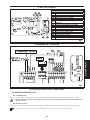 35
35
-
 36
36
-
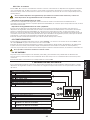 37
37
-
 38
38
-
 39
39
-
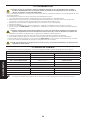 40
40
-
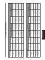 41
41
-
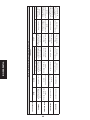 42
42
-
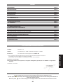 43
43
-
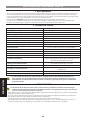 44
44
-
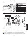 45
45
-
 46
46
-
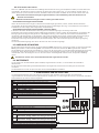 47
47
-
 48
48
-
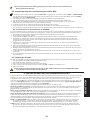 49
49
-
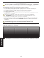 50
50
-
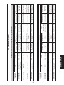 51
51
-
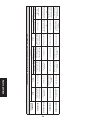 52
52
-
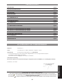 53
53
-
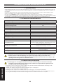 54
54
-
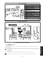 55
55
-
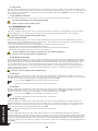 56
56
-
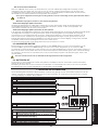 57
57
-
 58
58
-
 59
59
-
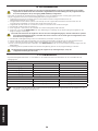 60
60
-
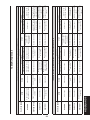 61
61
-
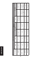 62
62
-
 63
63
-
 64
64


in altre lingue
- English: Genius LINX05 Operating instructions
- français: Genius LINX05 Mode d'emploi
- español: Genius LINX05 Instrucciones de operación
- Deutsch: Genius LINX05 Bedienungsanleitung
- Nederlands: Genius LINX05 Handleiding
Documenti correlati
-
Genius LINX05 Istruzioni per l'uso
-
-
Genius LINX07 Istruzioni per l'uso
-
Genius LYNX 08 Istruzioni per l'uso
-
-
-
-
-
-

