Fig. 1
JM.CB
L8542384
Rev. 04/07/00
SCHEDA CARICABATTERIA
BATTERY LOADER CARD
KARTE FÜR BATTERIELADEGERÄT
FICHE CHARGE BATTERIES
TARJETA CARGABATERÍA
KARTA ŁADOWARKI
KIT BATTERIE DI EMERGENZA JM.CB:
consente il funzionamento dell'automazione in assenza di
alimentazione di rete.
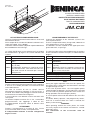
Il kit è composto da: scheda caricabatterie, 2 batterie 12V,
staffa di ssaggio, viti e cablaggi
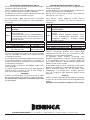
Le batterie vanno installate sulla parte superiore della base
del motoriduttore come da Fig.1.
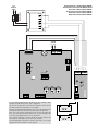
La scheda JM.CB deve essere collegata tra il secondario
del trasformatore e gli ingressi JP4, come indicato nello
schema.
+ + 24Vdc dalla batteria di emergenza
- - 24Vdc dalla batteria di emergenza
24trs
Collegare al secondario 24V del trasforma-
tore.
VMtrs
Collegare al secondario del trasformatore (da
20 a 35 Vac).
ATTENZIONE!: Seleziona la velocità di funzio-
namento del motore. Fate riferimento alle istru-
zioni della centrale di comando per il corretto
collegamento.
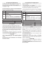
Caratteristiche Tecniche:
Corrente di carica 100mA
Tensionedi carica 27,2 Vdc
Tempo di carica (per batterie 2Ah) 20 ore circa
Note.
Durante il normale funzionamento di rete il LED verde DL2
è accesso e la scheda provvede al mantenimento della
carica delle batterie.
Nel caso di assenza di rete la scheda fornisce
alimentazione attraverso le batterie, il LED rosso DL1 si
accende. Un fusibile F10A protegge la centrale durante il
funzionamento con batteria di emergenza.
In assenza di rete e con batterie scariche entrambi i LED
sono spenti.
La batteria tampone funziona no a che, scaricandosi
progressivamente, non raggiunge il valore di 18V.
Al raggiungimento di questo valore la batteria viene
scollegata.
ATTENZIONE!
Durante il funzionamento in assenza di rete, l’uscita
accessori 24Vac della centrale, risulta polarizzata.
E’ indispensabile vericare il corretto collegamento
degli accessori.
JM.CB EMERGENCY BATTERY KIT:
It permits the operation of the automatic system in the
event of power failure.
The kit is composed of: battery charge card, 2 batteries at
12V, tting bracket, screws and cables.
The batteries must be installed on the upper part of the
gear motor basis, as per Fig.1.
The JM.CB card must be connected between the auxiliary
of thre transformer and the JP4 inputs, as indicated in the
diagram.
+ + 24Vdc to the emergency battery
- - 24Vdc from the emergency battery
24trs
Connect to the 24V auxiliary of the
transformer
VMtrs
Connect to the auxiliary of the transformer (20
to 35 Vac).
WARNING!: Select the operatine speed of the
motor. Read the instructions of the control unit
for the correct connection.
Specications:
Charging current 100mA
Charging voltage 27.2 Vdc
Charging time (for 2Ah batteries) Approx. 20 hours
Note.
During the regular operation with the mains power, the
DL2 green LED is switched on and the batteries are kept
charged through the card.
In the event of power failure, the card supplies power
supply through the batteries, the DL1red LED is switched
on. The F10A fuse provides protection to the control unit
during operation with the emergency battery.
In case of power failure and with batteries low, the LEDs
are off.
The buffer battery operates, and progressively lowers,
until 18V is reached. When this value is reached, the
battery is disconnected.
WARNING!
When operating without the mains power, the 24Vac
accessory output of the control unit becomes a 24Vdc
polarised current.
The connections of the accessories must be
checked.
La pagina si sta caricando...
La pagina si sta caricando...
La pagina si sta caricando...
-
 1
1
-
 2
2
-
 3
3
-
 4
4


in altre lingue
- English: Beninca JMCB User guide
- français: Beninca JMCB Mode d'emploi
- español: Beninca JMCB Guía del usuario
- Deutsch: Beninca JMCB Benutzerhandbuch
- polski: Beninca JMCB instrukcja