
VacIon Plus 20
pumps
Model 919-1115
Model 919-1125
Model 919-1145
Model 919-1146
Model 919-1114
Model 919-1124
Model 919-1144
(I) MANUALE DI ISTRUZIONI
(D) BEDIENUNGSHANDBUCH
(F) NOTICE DE MODE D’EMPLOI
(GB) INSTRUCTION MANUAL
87-900-106-01(B)
APRIL 2006

VacIon Plus 20


ISTRUZIONI PER L’USO .................................................................................................... 1
GEBRAUCHSANLEITUNG ................................................................................................. 3
MODE D’EMPLOI................................................................................................................ 5
INSTRUCTIONS FOR USE................................................................................................. 7
TECHNICAL INFORMATION .............................................................................................. 9
DESCRIPTION OF THE VACION PUMP......................................................................................9
TECHNICAL SPECIFICATION ......................................................................................................9
OUTLINE DRAWING ...................................................................................................................12
STRAY MAGNETIC FIELD..........................................................................................................13
VACION PLUS PUMP INSTALLATION.......................................................................................14
Inspection procedure .........................................................................................................14
Visual inspection................................................................................................................14
Vacuum evaluation ............................................................................................................14
Short circuits ......................................................................................................................14
TYPICAL INSTALLATION............................................................................................................14
INLET FLANGE CONNECTION ..................................................................................................15
CONTROL UNIT CONNECTION.................................................................................................16
SAFETY INTERLOCK..................................................................................................................16
HEATER INSTALLATION............................................................................................................16
HEATER REPLACEMENT...........................................................................................................17
BAKEOUT OPERATION..............................................................................................................17
Bakeout of VacIon pump with the integral heaters...........................................................17
OPERATING PROCEDURE........................................................................................................17
MAINTENANCE ...........................................................................................................................18
Exchange of the high voltage feedthrough........................................................................18
Leakage current check ......................................................................................................19
High-potting........................................................................................................................19
PUMP TROUBLESHOOTING .....................................................................................................20
VACION PLUS PUMP REPLACEMENT PARTS AND ACCESSORIES ....................................21
VACION PLUS PUMP CONTROLLER........................................................................................22

ISTRUZIONI PER L'USO
1 87-900-106-01(B)
INFORMAZIONI GENERALI
Questa apparecchiatura è destinata ad uso professionale. L'uti-
lizzatore deve leggere attentamente il presente manuale di i-
struzioni ed ogni altra informazione addizionale fornita dalla
Varian prima dell'utilizzo dell'apparecchiatura. La Varian si ritie-
ne sollevata da eventuali responsabilità dovute all'inosservanza
totale o parziale delle istruzioni, ad uso improprio da parte di
personale non addestrato, ad interventi non autorizzati o ad uso
contrario alle normative nazionali specifiche.
Le pompe della serie VacIon Plus sono pompe ioniche utilizza-
te comunemente per applicazioni di ultra alto vuoto, grazie alla
loro pulizia, capacità di pompare qualsiasi tipo di gas, e del loro
funzionamento senza vibrazioni e necessità di manutenzione.
Nei paragrafi seguenti sono riportate tutte le informazioni ne-
cessarie a garantire la sicurezza dell'operatore durante l'utilizzo
dell'apparecchiatura. Informazioni dettagliate sono fornite nel-
l'appendice “Technical information”.
Questo manuale utilizza le seguenti convenzioni:
,
PERICOLO!
I messaggi di pericolo attirano l'attenzione dell'operatore su una
una procedura o una pratica specifica che, se non eseguita in
modo corretto, potrebbe provocare gravi lesioni personali.
ATTENZIONE!
I messaggi di attenzione sono visualizzati prima di procedure
che, se non osservate, potrebbero causare danni all'apparec-
chiatura.
NOTA
Le note contengono informazioni importanti estrapolate dal te-
sto.
PREPARAZIONE PER L'INSTALLAZIONE
La pompa viene fornita in un imballo protettivo speciale; se si
presentano segni di danni, che potrebbero essersi verificati du-
rante il trasporto, contattare l'ufficio vendite locale. Durante l'o-
perazione di disimballaggio, prestare particolare attenzione a
non lasciar cadere la pompa e a non sottoporla ad urti o vibra-
zioni. Non disperdere l'imballo nell'ambiente. Il materiale è
completamente riciclabile e risponde alla direttiva CEE 85/399
per la tutela dell'ambiente.
ATTENZIONE!
Onde evitare problemi di degassamento, non toccare con le
mani nude i componenti destinati ad essere esposti al vuoto.
Utilizzare sempre i guanti o altra protezione adeguata.
NOTA
La pompa non può essere danneggiata rimanendo semplice-
mente esposta all'atmosfera. Si consiglia comunque di mante-
nerla chiusa fino al momento dell'installazione sul sistema onde
evitare eventuale inquinamento da polvere.
INSTALLAZIONE
Non installare e/o utilizzare la pompa in ambienti esposti ad agen-
ti atmosferici (pioggia, gelo, neve), polveri, gas aggressivi, in am-
bienti esplosivi o con elevato rischio di incendio. Durante il
funzionamento, per ottenere le specifiche tecniche dichiarate, la
temperatura ambiente deve essere compresa tra 0 °C e +85 °C.
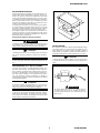
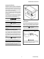
ATTENZIONE!
La pompa deve essere tenuta sigillata con il suo tubo di ingres-
so schiacciato finchè non è pronta per essere collegata al si-
stema.
NO!
,
PERICOLO!
Per evitare lesioni alla persona, non collegare l’alta ten-
sione alla pompa prima che sia installata nel sistema e
che tutte le flange di ingresso siano adeguatamente colle-
gate o chiuse.

ISTRUZIONI PER L'USO
Il funzionamento delle pompe è ottimizzato solo con l’uso delle
apposite unità di controllo Varian (Dual, MidiVac o MiniVac).
6. La pressione nella pompa può anche essere calcolata leg-
gendo la corrente e convertendo la lettura in pressione tra-
mite l’apposito diagramma pressione-corrente illustrato
nell’appendice “Technical Information” di questo manuale.
ATTENZIONE!
Il rispetto delle normative di sicurezza nell’uso delle pompe è
garantito solo con l’uso delle unità di controllo Varian.
NOTA
I gradini nei diagrammi pressione - corrente sono una caratteri-
stica del modo di funzionamento del Dual. Quando la corrente
assorbita dalla pompa raggiunge determinati valori, l'unità di
controllo cambia il valore dell'alta tensione in uscita ad un valo-
re più basso.
La pompa VacIon Plus può essere installata in qualsiasi posi-
zione. Per convenienza normalmente viene montata in posizio-
ne verticale con la flangia di ingresso in alto.
Le pompe possono anche essere mantenute sospese in ogni
posizione tramite la loro flangia di ingresso. Per informazioni
dettagliate sull’installazione della pompa, vedere l’appendice
"Technical Information".
7. Quando si porta la pompa alla pressione atmosferica, usare
azoto secco in modo da evitare l’assorbimento di vapore
acqueo da parte delle pareti della pompa.
USO
,
Tutte le istruzioni per il corretto funzionamento delle pompe Va-
cIon Plus sono contenute nel manuale dell'unità di controllo. Leg-
gere attentamente tale manuale prima dell'utilizzo. Si raccomanda
di portare la pompa ad una pressione di 1x10
PERICOLO!
Quando la pompa viene utilizzata per il pompaggio di gas tos-
sici, infiammabili o radioattivi, seguire le appropriate procedure
tipiche di ciascun gas. Non usare la pompa in presenza di gas
esplosivi.
-4
Torr (mbar) in mo-
do da ottenere un avvio più rapido. A questo scopo è meglio non
utilizzare una pompa meccanica sigillata con olio, ma se deve
essere utilizzata una tale pompa, si raccomanda di inserire una
trappola lungo la linea di vuoto per ridurre la pressione causata
dai vapori di acqua e di olio provenienti dalla pompa meccanica.
Cercare di ridurre al minimo il tempo in cui la pompa meccanica è
aperta verso il sistema e verso la pompa ionica, poiché i suoi va-
pori si diffondono nel sistema a pressioni inferiori a 1x10
,
PERICOLO!
Quando è installato il riscaldatore, non toccare la pompa duran-
te le operazioni di riscaldamento e di raffreddamento. L'elevata
temperatura può causare lesioni alle persone.
-1
Torr
(mbar) causando una contaminazione dello stesso. Nei sistemi in
cui l’olio deve essere completamente assente, è meglio utilizzare
pompe Turbo per la suddetta operazione. Depositi igroscopici e
l’assorbimento dell’idrogeno all’interno del composto di titanio
possono provocare l’allungamento del tempo di avvio con
l’invecchiamento della pompa. Durante l’esposizione all’aria, il
deposito del composto di titanio assorbe vapore acqueo; in con-
seguenza di ciò, al successivo avvio, il riscaldamento della pom-
pa provoca il rilascio del vapore e di parte dell’idrogeno pompato
precedentemente, con l’effetto dell’allungamento del tempo di
avvio.
ATTENZIONE!
Non avvicinare dispositivi elettronici alla pompa. Il campo ma-
gnetico attorno ad essa può provocare dei malfunzionamenti
dei dispositivi stessi.
MANUTENZIONE
Le pompe della serie VacIon Plus non richiedono alcuna manu-
tenzione. Qualsiasi intervento deve essere eseguito da
personale autorizzato.
Procedure di uso
,
Controllare che la polarità dell’unità di controllo sia corretta per
la pompa: polarità positiva per le pompe Diode e negativa per
le StarCell. Fare riferimento al relativo manuale ed osservare la
seguente procedura per l’uso della pompa:
PERICOLO!
Prima di effettuare qualsiasi intervento sulla pompa scollegarla
dall’alta tensione.
1. Tramite una pompa di pre-vuoto portare il sistema da vuoto
ad una pressione minima di avvio in accordo alla tabella di
pagina 9 ed a seconda del tipo di pompa ionica.
Qualora una pompa dovesse essere rottamata, procedere alla
sua eliminazione nel rispetto delle normative nazionali specifi-
che.
2. Collegare l’unità di controllo ad una apposita fonte di ali-
mentazione ed accenderla.
3. Osservare la tensione, la corrente e la pressione. Se l’avvio
è avvenuto ad una pressione di 5x10
SMALTIMENTO
-2
Torr (mbar), è tipica
una tensione di circa 300 - 400 V. Un valore di corrente
prossimo alla corrente di corto circuito dell’unità di controllo
è indice dell’esistenza di una perdita nella pompa e nel si-
stema. Un temporaneo incremento della pressione di pre-
vuoto è normale durante la fase di avvio.
Significato del logo "WEEE" presente sulle etichette
Il simbolo qui sotto riportato applicato in ottemperanza alla di-
rettiva CE denominata "WEEE".
Questo simbolo (valido solo per i paesi della Comunità Eu-
ropea) indica che il prodotto sul quale è applicato, NON deve
essere smaltito insieme ai comuni rifiuti domestici o industriali,
ma deve essere avviato ad un sistema di raccolta differenziata.
4. Lasciare la valvola di pre-vuoto aperta durante l’avvio della
pompa ionica finchè non si raggiunge una adeguata pres-
sione di avvio. Se la tensione della pompa ionica scende
dopo la chiusura della valvola, riaprirla per un pre-
pompaggio aggiuntivo. Appena la pressione diminuisce, la
tensione cresce nuovamente e la valvola di pre-vuoto può
essere chiusa.
Si invita pertanto l'utente finale a contattare il fornitore del di-
spositivo, sia esso la casa madre o un rivenditore, per avviare il
processo di raccolta e smaltimento, dopo opportuna verifica dei
termini e condizioni contrattuali di vendita.
5. Quando la tensione ha raggiunto i 2 - 3kV, mettere l’unità di
controllo nello stato PROTECT. Il sistema sarà così auto-
protetto dall’incremento della pressione oltre 1x10
-4
Torr
(mbar) quando la pompa non è controllata. Nel caso in cui
ci fosse un tale incremento, l’unità di controllo viene spenta
automaticamente.
2 87-900-106-01(B)

GEBRAUCHSANWEISUNGEN
ALLGEMEINE HINWEISE
Dieses Gerät ist für den professionellen Gebrauch bestimmt.
Vor dem Gebrauch soll der Benutzer dieses Handbuch sowie
alle weiteren von Varian mitgelieferten Zusatzdokumentationen
genau lesen. Bei vollständiger bzw. teilweiser Nichtbeachtung
der enthaltenen Hinweise, unsachgemäßem Gebrauch durch
ungeschultes Personal, nicht autorisierten Eingriffen und Mi-
ßachtung der nationalen Bestimmungen übernimmt Firma Vari-
an keinerlei Haftung.
Die Pumpen der Serie VacIon Plus sind Ionenpumpen, die auf-
grund ihrer Reinheit, ihrer Fähigkeit, alle Arten von Gas zu
pumpen, und ihres vibrations- und wartungsfreien Betriebes,
allgemein für Ultrahochvakuumanwendungen zum Einsatz
kommen.
In den folgenden Abschnitten sind alle erforderlichen Informati-
onen für die Sicherheit des Bedieners bei der Anwendung des
Geräts aufgeführt. Detaillierte technische Informationen sind im
Anhang "Technical Information" enthalten.
In dieser Gebrauchsanleitung werden Sicherheitshinweise
folgendermaßen hervorgehoben:
,
GEFAHR!
Die Gefahrenhinweise lenken die Aufmerksamkeit des Bedie-
ners auf eine spezielle Prozedur oder Praktik, die bei unkorrek-
ter Ausführung schwere Verletzungen hervorrufen könnte.
INSTALLATION
Die Pumpe darf nicht in Umgebungen installiert und/oder be-
nutzt werden, die ungeschützt vor Witterungsbedingungen (Re-
gen, Frost, Schnee), Staub und aggressiven Gasen sind, und in
denen Explosions- und erhöhte Brandgefahr besteht.
ACHTUNG!
Die Warnhinweise vor bestimmten Prozeduren machen den
Bediener darauf aufmerksam, daß bei Nichteinhaltung Schäden
am Gerät entstehen können.
Während des Betriebes soll die Umgebungstemperatur zwi-
schen 0°C und +85°C betragen, um die angegebenen techni-
schen Merkmale zu gewährleisten.
ANMERKUNG
ACHTUNG!
Die Anmerkungen enthalten wichtige Informationen, die aus
dem Text hervorgehoben werden.
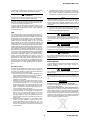
Die Pumpe soll versiegelt und mit flachgedrücktem Eintritts-
schlauch gehalten werden, bis sie für den Anschluß an das
System bereit ist.
VOR DER INSTALLATION
Die Pumpe wird in einer speziellen Schutzverpackung geliefert.
Eventuelle Transportschäden sind der zuständigen örtlichen
Verkaufsstelle zu melden. Beim Auspacken vorsichtig vorge-
hen, damit die Pumpe nicht fällt oder Stößen oder Vibrationen
ausgesetzt wird. Das Verpackungsmaterial ist ordnungsgemäß
zu entsorgen. Es ist vollständig recyclebar und entspricht der
EG-Richtlinie 85/399 für den Umweltschutz.
FALSCH!
ACHTUNG!
Um Entgasungsprobleme zu vermeiden, dürfen die Komponen-
ten, die mit dem Vakuum in Kontakt kommen, nicht mit bloßen
Händen berührt werden. Stets Handschuhe oder einen anderen
geeigneten Schutz tragen.
,
GEFAHR!
Um Personenschäden zu vermeiden, darf die Hochspan-
nungsleitung der Pumpe erst angeschlossen werden, wenn
die Pumpe im System installiert ist und alle Eintrittsflansche
entsprechend angeschlossen oder geschlossen sind.
ANMERKUNG
Die Pumpe kann, wenn sie einfach der Atmosphäre ausgesetzt
ist, nicht beschädigt werden. Sie sollte jedoch bis zur Installati-
on an der Anlage geschlossen bleiben, um Verunreinigungen
durch Staub zu vermeiden.
3 87-900-106-01(B)

GEBRAUCHSANWEISUNGEN
Der Pumpenbetrieb wird nur durch den Einsatz speziell dafür
vorgesehener Varian Steuereinheiten (Dual, MidiVac oder Mi-
niVac) optimiert.
ACHTUNG!
Die Einhaltung der Sicherheitsvorschriften beim Gebrauch der
Pumpen ist nur bei Verwendung von Varian Steuereinheiten
gewährleistet.
Die Pumpe VacIon Plus kann in einer beliebigen Position instal-
liert werden. Aus praktischen Gründen wird sie in der Regel
senkrecht mit nach oben gerichtetem Eintrittsflansch. Die Pum-
pen können auch in einer beliebigen Position an ihrem Eintritts-
flansch hängend eingebaut werden. Detaillierte Informationen
zur Installation der Pumpe sind dem Anhang “Technical Infor-
mation” zu entnehmen.
GEBRAUCH
Sämtliche Hinweise für den korrekten Betrieb der Pumpen Va-
cIon Plus sind im Handbuch der Steuereinheit enthalten. Die-
ses Handbuch ist vor der Inbetriebnahme genau durchzulesen.
Es wird empfohlen, die Pumpe auf einen Druck von 1x10
-4
Torr
(mbar) zu bringen, um einen rascheren Anlauf zu gewährleis-
ten. Zu diesem Zweck empfiehlt es sich, keine ölversiegelte
mechanische Pumpe zu verwenden. Falls hingegen eine derar-
tige Pumpe benutzt werden muß, soll an der Vakuumleitung
eine Falle eingesetzt werden, um den durch die Wasser- und
Öldämpfe aus der mechanischen Pumpe erzeugten Druck zu
verringern. Es ist zu versuchen, die Zeit auf ein Mindestmaß zu
reduzieren, während der die mechanische Pumpe zum System
und zur Ionenpumpe geöffnet ist, da sich ihre Dämpfe bei Drü-
cken unter 1x10
-1
Torr (mbar) im System verbreiten und dessen
Verunreinigung verursachen. Bei Systemen, die vollkommen
ölfrei sein müssen, erweisen sich für den obengenannten Vor-
gang Turbopumpen als geeigneter. Hygroskopische Ablage-
rungen und die Absorption von Wasserstoff in der
Titanverbindung können die Anlaufzeit verlängern und eine
kürzere Standzeit der Pumpe verursachen. Die Ablagerungen
der Titanverbindungen absorbieren Wasserdampf, wenn sie der
Luft ausgesetzt werden. Dadurch bewirkt beim anschließenden
Anlaufvorgang die Aufheizung der Pumpe die Abgabe des
Dampfes und eines Teils des zuvor gepumpten Wasserstoffs,
so daß sich die Anlaufzeit verlängert.
Bedienungsschritte
Es ist zu kontrollieren, daß die Steuereinheit in bezug auf die
Pumpe richtig gepolt ist: positive Polarität für Dioden Pumpen
und negative für StarCell Pumpen. Es ist nach dem diesbezüg-
lichen Handbuch vorzugehen, für den Gebrauch der Pumpe
sind die folgenden Bedienungsschritte zu beachten:
1. Mit einer Vorvakuumpumpe das System auf einen Min-
destanlaufdruck gemäß Tabelle 9 in Abhängigkeit vom Io-
nenpumpentyp bringen.
2. Die Steuereinheit an eine entsprechende Versorgungs-
quelle anschließen und einschalten.
3. Die Spannung, die Stromstärke und den Druck beobach-
ten. Wenn der Anlauf bei einem Druck von 5x10
-2
Torr
(mbar) erfolgt ist, ist eine Spannung von ca. 300 – 400 V
typisch. Ein Stromwert, der sich dem Kurzschlußstromwert
der Steuereinheit annähert, weist auf eine Leckstelle an
der Pumpe und am System hin. Ein zeitweiliger Anstieg
des Vorvakuumdruckes ist während der Anlaufphase nor-
mal.
4. Während des Anlaufes der Ionenpumpe soll das Vorvaku-
umventil geöffnet bleiben, bis ein angemessener Anlauf-
druck erreicht ist. Wenn die Spannung der Ionenpumpe
nach Schließung des Ventils abfällt, ist das Ventil für eine
zusätzliche Vorvakuumpumpung zu öffnen. Sobald der
Druck sinkt, steigt die Spannung erneut an und kann das
Vorvakuumventil geschlossen werden.
5. Wenn die Spannung 2 – 3 kV erreicht hat, ist die Steuer-
einheit auf den Status PROTECT zu schalten. Das System
verfügt auf diese Weise über einen Selbstschutz vor ei-
nem Druckanstieg über 1x10
-4
Torr (mbar), wenn die
Pumpe nicht kontrolliert ist. Falls ein solcher Anstieg statt-
findet, wird die Steuereinheit automatisch ausgeschaltet.
6. Der Pumpendruck kann auch berechnet werden, indem
die Stromstärke abgelesen wird und der abgelesene Wert
mittels des Druck-Stromstärke-Diagramms im Anhang
“Technical Information” des vorliegenden Handbuches in
einen Druckwert umgerechnet wird.
ANMERKUNG
Die Stufen im Druck-Stromstärke-Diagramm sind charakteris-
tisch für die Funktionsweise des Dual. Wenn die Stromaufnah-
me der Pumpe ein bestimmtes Ausmaß erreicht, ändert die
Steuereinheit die ausgangsseitige Hochspannung auf einen
niedrigeren Wert ab.
7. Wenn die Pumpe auf den atmosphärischen Druck ge-
bracht wird, ist trockener Stickstoff zu verwenden, um die
Aufnahme von Wasserdampf durch die Pumpenwände zu
verhindern.
,
GEFAHR!
Wenn die Pumpe zur Förderung von giftigen, leicht entflamm-
baren oder radioaktiven Gasen benutzt wird, sind die für das
jeweilige Gas vorgeschriebenen Vorgänge zu befolgen. Die
Pumpe nie bei Vorhandensein von explosivem Gas benutzen.
,
GEFAHR!
Wenn die Heizung installiert ist, darf die Pumpe während der
Aufheizung und Abkühlung nicht berührt werden. Die hohe
Temperatur kann zu Personenschäden führen.
ACHTUNG!
Keine elektronischen Geräte in die Nähe der Pumpe bringen.
Das darum befindliche Magnetfeld kann zu Funktionsstörungen
der Geräte führen.
WARTUNG
Die Pumpen der Serie VacIon Plus erfordern keine Wartung.
Sämtliche Eingriffe dürfen nur von autorisiertem Personal vor-
genommen werden.
,
GEFAHR!
Vor Eingriffen an der Pumpe ist diese von der Hochspannungs-
quelle zu trennen.
Bei eventueller Verschrottung einer Pumpe ist diese entspre-
chend der einschlägigen nationalen Vorschriften zu entsorgen.
ENTSORGUNG
Bedeutung des "WEEE" Logos auf den Etiketten
Das folgende Symbol ist in Übereinstimmung mit der EU-
Richtlinie WEEE (Waste Electrical and Electronic Equipment)
angebracht.
Dieses Symbol (nur in den EU-Ländern gültig) zeigt an, dass
das betreffende Produkt nicht zusammen mit Haushaltsmüll
entsorgt werden darf sondern einem speziellen Sammelsystem
zugeführt werden muss.
Der Endabnehmer sollte daher den Lieferanten des Geräts -
d.h. die Muttergesellschaft oder den Wiederverkäufer - kontak-
tieren, um den Entsorgungsprozess zu starten, nachdem er die
Verkaufsbedingungen geprüft hat.
4 87-900-106-01(B)

INSTRUCTIONS D’UTILISATION
INDICATIONS GÉNÉRALES
Cet appareillage a été conçu en vue d’une utilisation profes-
sionnelle. Il est conseillé à l’utilisateur de lire attentivement
cette notice d’instructions ainsi que toute autre indication sup-
plémentaire fournie par Varian avant d’utiliser l’appareil. Varian
décline toute responsabilité en cas de non respect total ou par-
tiel des instructions fournies, d’opérations non autorisées,
d’utilisation impropre par du personnel non formé ou contraires
aux réglementations nationales spécifiques.
Grâce à leur propreté, à leur capacité de pomper tous les types
de gaz, à leur fonctionnement sans vibrations et à l’absence
d’entretien, les pompes de la série Vacion Plus sont des pom-
pes ioniques généralement utilisées pour des applications de
vide ultra poussé.
Les paragraphes suivants fournissent toutes les indications
nécessaires à garantir la sécurité de l'opérateur pendant l'utili-
sation de l'appareillage. Des renseignements plus détaillés se
trouvent dans l'appendice "Technical Information".
Cette notice utilise les signes conventionnels suivants:
,
DANGER!
Les messages de danger attirent l'attention de l'opérateur sur
une procédure ou une manoeuvre spéciale dont la mauvaise
exécution peut provoquer de graves lésions.
INSTALLATION
Ne pas installer et/ou utiliser la pompe dans des milieux expo-
sés à des agents atmosphériques (pluie, gel, neige), à des
poussières, à des gaz de combat ainsi que dans des milieux
explosifs ou à fort risque d'incendie. Pendant le fonctionne-
ment, pour respecter les spécifications techniques déclarées la
température ambiante doit être comprise entre 0°C et +85°C;
ATTENTION!
Les messages d'attention apparaissent avant certaines procé-
dures dont le non respect peut provoquer des dommages irré-
versibles à l'appareillage.
NOTE
ATTENTION!
Les notes contiennent des renseignements importants, extrapo-
lés du texte.
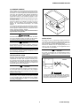
La pompe doit être conservée scellée avec son tuyan d’entrée
aplati jusqu’à ce qu’elle soit prête à être branchée au système.
PRÉPARATION DE L'INSTALLATION
La pompe est fournie dans un emballage de protection spécial;
si l'on constate des signes d’endommagement imputables au
transport, contacter aussitôt le revendeur local. Pendant l'opé-
ration de déballage, veiller tout particulièrement à ne pas lais-
ser tomber la pompe et à ne lui faire subir aucun choc ni
aucune vibration. Ne pas abandonner l'emballage dans la na-
ture. Le matériel est entièrement recyclable et il est conforme à
la directive CEE 85/399 en matière de protection de l'environ-
nement.
NON!
ATTENTION!
En vue d'éviter tout problème de dégazage, ne pas toucher à
mains nues les éléments devant être exposés au vide. Mettre
toujours des gants ou toute autre protection appropriée.
,
DANGER!
Pour éviter toute lésion aux personnes, ne pas brancher la
haute tension à la pompe avant que celle-ci soit installée
dans le système et avant que toutes les brides d’entrées
soient correctement assemblées ou fermées.
NOTE
La pompe ne peut être endommagée si elle reste simplement
exposée à l'atmosphère. Il est quoi qu’il en soit conseillé de ne
pas la retirer de son emballage avant le moment de l'installa-
tion, afin d'éviter toute pollution due à la poussière.
5 87-900-106-01(B)

INSTRUCTIONS D’UTILISATION
Le fonctionnement de la pompe n'est optimisé que si celle-ci
est utilisée avec l'une des unités de contrôle Varian spécifiques
(Dual, MidiVac ou MiniVac).
ATTENTION!
Lors de l'utilisation des pompes, le respect des normes de sé-
curité est impérativement subordonné à l'emploi des unités de
contrôle Varian.
La pompe Vacion Plus peut être installée dans toutes les posi-
tions. Par facilité elle est généralement montée en position ver-
ticale avec bride d’entrée en partie haute. Les pompes peuvent
également être suspendues dans toutes les positions à l’aide
de leur bride d’entrée. Pour plus de détails sur l’installation de
la pompe, consulter l’appendice “Technical information”.
UTILISATION
Toutes les instructions pour le fonctionnement correct de la
pompe Vacion Plus sont fournies dans la notice de l'unité de
contrôle. Il est conseillé de lire attentivement cette notice avant
d'utiliser la pompe. Il est recommandé de porter la pompe à
une pression de 1x10
-4
Torrs (mbars) de façon à obtenir un dé-
marrage plus rapide. Pour ce faire il est préférable de ne pas
utiliser une pompe mécanique scellée à l’huile mais au cas où il
serait nécessaire d’utiliser une telle pompe, il est recommandé
d’introduire un dispositif de retenue le long de la ligne de vide
afin de réduire la pression due aux vapeurs d’eau et d’huile en-
gendrées par la pompe mécanique. Essayer de réduire au mi-
nimum le temps où la pompe mécanique est ouverte vers le
système et vers la pompe ionique car ses vapeurs se répan-
dent dans le système à des pressions inférieures à 1x10
-1
Torrs
(mbars) causant une contamination de celui-ci. Dans les sys-
tèmes où l’huile doit être complètement absente, il est préféra-
ble d’effectuer ladite opération à l’aide d’une pompe Turbo. Des
dépôts hygroscopiques et l’absorption d’hydrogène dans le
composé de titane peuvent provoquer, par effet du vieillisse-
ment de la pompe, l’allongement du temps de démarrage. Pen-
dant l’exposition à l’air, le dépôt du composé de titane absorbe
de la vapeur d’eau et cette action a pour conséquence qu’au
démarrage suivant le chauffage de la pompe entraînera la dis-
persion de la vapeur et d’une partie de l’hydrogène pompée
précédemment ce qui aura pour effet d’allonger le temps de
démarrage.
Procédure d’utilisation
Contrôler que la polarité de l’unité de contrôle soit correcte pour
la pompe: polarité positive pour les pompes Diode et négative
pour les pompes StarCell. Se reporter au manuel corres-
pondant et observer la procédure suivante pour l’utilisation de
la pompe:
1. A l'aide d'une pompe de pré-vide, porter le système à une
pression minimale de démarrage en suivant le tableau de
la page 9 et en fonction du type de pompe ionique.
2. Brancher l’unité de contrôle à une source d’alimentation
appropriée et l’allumer.
3. Contrôler la tension, le courant et la pression. Lorsque la
mise en route est effectuée à une pression de 5x10
-2
Torrs
(mbars) la tension est généralement d’environ 300 - 400
V. Une valeur de courant proche du courant de court-
circuit de l’unité de contrôle révèle l’existence d’une fuite
dans la pompe et dans le système. Au cours de la phase
de démarrage, un accroissement momentané de la pres-
sion de pré-vide est normal.
4. Laisser la soupape de pré-vide ouverte pendant le démar-
rage de la pompe ionique tant qu’une pression de démar-
rage appropriée n’a pas été atteinte. Si la tension de la
pompe ionique descend après la fermeture de la soupape,
la rouvrir pour un pré-pompage supplémentaire. Dès que
la pression commence à diminuer, la tension augmente à
nouveau et la valve de pré-vide peut être fermée.
5. Lorsque la tension a atteint 2 - 3 kV, mettre l’unité de
contrôle en état de PROTECT. Le système sera ainsi pro-
tégé contre toute augmentation de pression au-delà de
1x10
Torrs (mbars) lorsque la pompe n’est pas contrôlée.
Si une telle augmentation devait être enregistrée, l’unité
de contrôle s’éteindrait automatiquement.
6. La pression de la pompe peut également être calculée en
relevant le courant et en convertissant la lecture en pres-
sion à l’aide du diagramme pression-courant illustré dans
l’appendice “Technical Information” de ce manuel.
NOTE
Les paliers du diagramme de pression – courant sont une ca-
ractéristique du mode de fonctionnement du Dual. Lorsque le
courant absorbé par la pompe atteint des valeurs déterminées,
l'unité de contrôle porte la valeur de haute tension en sortie à
une valeur inférieure.
7. Lorsque l’on porte la pompe à la pression atmosphérique ,
utiliser de l’azote sec de façon à éviter que les parois de la
pompe n’absorbent de la vapeur aqueuse.
,
DANGER!
Lorsque la pompe est utilisée pour le pompage de gaz toxi-
ques, inflammables ou radioactifs, suivre les procédures ap-
propriées à chaque gaz. Ne pas utiliser la pompe en présence
de gaz explosifs.
,
DANGER!
Lorsque le réchauffeur est installé, éviter de toucher la pompe
pendant les opérations de chauffage et de refroidissement. La
température élevée peut provoquer des brûlures.
ATTENTION!
Ne pas approcher de dispositifs électroniques de la pompe. Le
champ magnétique environnant cette dernière peut entraîner
des dysfonctionnements desdits dispositifs.
MAINTENANCE
Les pompes de la série Vacion Plus ne demandent aucun en-
tretien. Toute intervention doit être exécutée par un personnel
agréé.
,
DANGER!
Avant toute intervention sur la pompe, la débrancher de la
haute tension.
En cas de mise au rebut d’une pompe, procéder à son élimina-
tion dans le respect des normes nationales en vigueur.
MISE AU REBUT
Signification du logo "WEEE" figurant sur les étiquettes
Le symbole ci-dessous est appliqué conformément à la direc-
tive CE nommée "WEEE".
Ce symbole (uniquement valide pour les pays de la Com-
munauté européenne) indique que le produit sur lequel il est
appliqué NE doit PAS être mis au rebut avec les ordures mé-
nagères ou les déchets industriels ordinaires, mais passer par
un système de collecte sélective.
Après avoir vérifié les termes et conditions du contrat de vente,
l’utilisateur final est donc prié de contacter le fournisseur du
dispositif, maison mère ou revendeur, pour mettre en œuvre le
processus de collecte et mise au rebut.
-4
6 87-900-106-01(B)

INSTRUCTIONS FOR USE
GENERAL INFORMATION
This equipment is destined for use by professionals. The user
should read this instruction manual and any other additional
information supplied by Varian before operating the equipment.
Varian will not be held responsible for any events occurring due
to non-compliance, even partial, with these instructions, im-
proper use by untrained persons, non-authorized interference
with the equipment or any action contrary to that provided for by
specific national standards.
The VacIon Plus series pumps are ion pumps commonly used
to create ultra-high vacuum, due to their cleanliness, ability to
pump different gases, and maintenance- and vibration-free op-
eration.
The following paragraphs contain all the information necessary
to guarantee the safety of the operator when using the equip-
ment. Detailed information is supplied in the appendix "Techni-
cal Information".
This manual uses the following standard protocol:
,
WARNING!
The warning messages are for attracting the attention of the
operator to a particular procedure or practice which, if not fol-
lowed correctly, could lead to serious injury.
INSTALLATION
Do not install or use the pump in an environment exposed to
atmospheric agents (rain, snow, ice), dust, aggressive gases,
or in explosive environments or those with a high fire risk. Dur-
ing operation, to obtain the specified operation, the ambient
temperature must be between 0 °C and +85 °C.
CAUTION
The caution messages are displayed before procedures which,
if not followed, could cause damage to the equipment.
CAUTION
NOTE
The notes contain important information taken from the text.
The pump should be kept sealed with its pinch-off tube until it is
ready for attachment to the vacuum system.
PREPARATION FOR INSTALLATION
The pump is supplied in a special protective packing. If this
shows signs of damage which may have occurred during trans-
port, contact your local sales office. When unpacking the pump,
be sure not to drop it and avoid any kind of sudden impact or
shock vibration to it. Do not dispose of the packing materials in
an unauthorized manner. The material is 100% recyclable and
complies with EEC Directive 85/399.
NO!
CAUTION
In order to prevent outgassing problems, do not use bare hands
to handle components which will be exposed to vacuum. Al-
ways use gloves or other appropriate protection.
,
WARNING!
NOTE
To avoid injury, never connect the high voltage to the pump
before it is installed into the system and all the inlet flanges
are properly connected or blanked off.
Normal exposure to the environment cannot damage the pump.
Nevertheless, it is advisable to keep it closed until it is installed
in the system, thus preventing any form of pollution by dust.
7 87-900-106-01(B)

INSTRUCTIONS FOR USE
The pump operation is optimized using one of the special Var-
ian controllers (Dual, MidiVac or MiniVac) only.
6. The pressure in the pump can also be determined by read-
ing the current and converting this reading to pressure with
the appropriate pressure versus current graph shown in the
appendix “Technical Information” of this manual.
CAUTION
NOTE
The safety specifications agreement using the pump is guaran-
teed using the Varian controller only.
The steps on the pressure – current charts are a characteristic
of the Dual step voltage operation. When the current drawn by
the VacIon pump reaches the specified values, the controller
will change the high voltage output to a lower applied voltage.
The VacIon Plus pump can be installed in any position. For
convenience, a pump is usually mounted vertically with the inlet
up. Pumps can be supported by the mounting flange in any po-
sition. For detailed information about the pump installation, see
the appendix “Technical Information”.
7. When venting the pump, use dry nitrogen. This will avoid
water vapor absorption on the pump walls.
USE
,
WARNING!
All the instructions for the correct use of the VacIon Plus pumps
are contained in the control unit manual. Read the manual care-
fully before using the pump. Rough pumping down to 1x10
When employing the pump for pumping toxic, flammable, or
radioactive gases, please follow the required procedures for
each gas disposal. Do not use the pump in presence of explo-
sive gases.
-4
Torr (mbar) is recommended for the most rapid starting. Rough-
ing with an oil-sealed mechanical pump is not desirable, but
when used, a trap in the roughing line is recommended to re-
duce pressure due to water vapor and oils from the mechanical
pump. Be careful to minimize the time that the mechanical
pump is open to the system and ion pump, since mechanical
pump vapors will start diffusing into the system at pressures
below 1x10
,
WARNING!
When the heating element is installed, do not touch the pump
during the heating and cooling phases. The high temperature
may cause a serious damage.
-1
Torr (mbar) and cause contamination. In systems
where oils must be completely eliminated, turbopump roughing
pumps should be used. Hygroscopic deposits and hydrogen
absorption into titanium may cause starting times to increase
with age. During exposure to air, the deposits of titanium com-
pound absorb water vapor. In subsequent start ups, pump heat-
ing causes release of the water vapor and some previously
pumped hydrogen; thus, the starting time may be lengthened.
CAUTION
Do not put any electronic device near the pump otherwise the
magnetic field around it may cause a device malfunctioning.
MAINTENANCE
Operating procedure
The VacIon Plus series pump does not require any mainte-
nance. Any work performed on the pump must be carried out by
authorized personnel.
Check that the controller HV polarity is correct for the pump:
positive polarity for Diode pumps and negative for StarCell
pumps. Refer to the relevant pump control unit instruction man-
ual and follow the procedure below when operating the pump:
,
WARNING!
1. With a clean roughing pump, establish a minimum starting
pressure in the vacuum system per the table on page 9 for
the type of ion pump.
Before carrying out any work on the pump, disconnect it from
the High Voltage supply.
2. Plug the control unit into a suitable power source and
switch the power ON.
If a pump is to be scrapped, it must be disposed of in accor-
dance with the specific national standards.
3. Observe the voltage, current, and roughing pressure. If
started at 5x10
-2
Torr (mbar), a controller voltage of ap-
proximately 300 to 400 volts is typical. A current value near
the short-circuit current of the control unit could indicate
that an unconfined flow discharge exists in the pump and
system. A temporary rise in roughing pressure will usually
be noticed during any starting procedure.
DISPOSAL
Meaning of the "WEEE" logo found in labels
The following symbol is applied in accordance with the EC
WEEE (Waste Electrical and Electronic Equipment) Directive.
4. Allow the roughing valve to remain open after turning on the
ion pump until an adequate starting pressure is reached. If
the ion pump voltage drops after closing the roughing
valves, reopen the valve for additional rough pumping. As
the pressure decreases, the voltage again will rise, and the
roughing valve may be closed.
This symbol (valid only in countries of the European Com-
munity) indicates that the product it applies to must NOT be
disposed of together with ordinary domestic or industrial waste
but must be sent to a differentiated waste collection system.
The end user is therefore invited to contact the supplier of the
device, whether the Parent Company or a retailer, to initiate the
collection and disposal process after checking the contractual
terms and conditions of sale.
5. When the voltage has increased to 2-3 kV, place the control
unit in the PROTECT condition. The system is now auto-
matically protected against pressure increases to 10
-4
Torr
(mbar) when the pump is left unattended. If such an in-
crease should occur, the control unit will be turned off
automatically.
8 87-900-106-01(B)

TECHNICAL INFORMATION
DESCRIPTION OF THE VACION PUMP
The Varian VacIon Plus 20 pumps are ion pumps
and are available in three types:
• StarCell
• Noble Diode
• Diode
They operate in the pressure range from 10
-2
to
below 10
-11
Torr (mbar). Virtually all gases and va-
pors can be pumped successfully with the ion
pump. The pumping speed will vary depending on
the system pressure, the gas type, and the applied
operating voltage. The latter can be optimized us-
ing Varian controllers to achieve the lowest possi-
ble operating pressure.
The VacIon Plus StarCell pumps allow starting
from as high as 5x10
-2
Torr (6.6x10
-2
mbar), be-
cause ions are prevented from bombarding the
system and pump walls at starting pressures, and
have high speed for inert gases. The VacIon Plus
Diode and Noble Diode pumps require a lower
starting pressure (i.e. 10
-3
Torr (mbar)). The Diode
contains more titanium than triode pumps, and
thus has a higher hydrogen capacity and longer
life.
The tantalum in the Noble Diode pump enhances
the noble gas pumping capacity, although it
somewhat reduces the high getterable gas pump-
ing speed that the standard diode pump provides.
The VacIon Plus StarCell is the latest version of
this pump. Its patented design makes this ion
pump the only one that can handle a high amount
of Noble Gases (equal or better than Noble Diode)
and Hydrogen (comparable to the Diode).
A positive polarity, high voltage supply is required
to operate Diode and Noble Diode pumps. A nega-
tive polarity high voltage supply is required to op-
erate StarCell pump since the anode is grounded
and the cathode is held at negative potential.
The pump can operate in any position and can be
supported on the mounting flange. The inlet Con-
Flat flange is a 2 3/4” (NW 35).
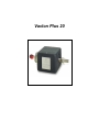
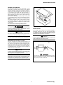
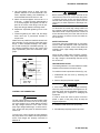
Fig. 1 shows the VacIon Plus 20 pump, Fig. 2
shows the main assemblies of the pump.
Fig. 1 - VacIon Plus 20 pump
Fig. 2 - Pump main assemblies
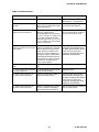
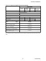
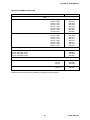
TECHNICAL SPECIFICATION
The following table details the main technical
specifications of the VacIon Plus 20 pumps.
MODEL
SPECIFICATION
STARCELL
NOBLE
DIODE
DIODE
Nominal pumping
speed for Nitrogen
(*) (l/s)
20 22 27
Operating life at
1x10
-6
mbar (hours)
80,000 50,000 50,000
Operating voltage
(max)
-7000 Vdc
+/- 10%
+7000 Vdc
+/- 10%
Max starting current 150 mA
Max baking current 10 mA
Protect current 20 mA
Maximum starting
pressure (mbar)
≤5x10
-2
≤1x10
-3
Ultimate pressure Below 10
-11
Inlet flange 2 3/4” CFF (NW 35) AISI 304 ESR SST
Internal volume (li-
tres)
0.9
Maximum baking
temperature (°C)
350
Temperature limits
(°C): Pump
Magnet (ferrite)
Flange
400
350
500
Material: Body AISI 304 SST
Cathode Titanium Titanium/
Tantalum
Titanium
Anode AISI 304 SST
Magnet Ferrite or Sm-Co
Weight, lbs (kg)
with ferrite magnet
with Sm-Co magnet
7 (11)
5 (8)
(*) Tested according to ISO/DIS 3556-1-1992
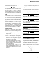
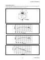
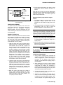
Figures 3 to 10 show the pumping speed vs pres-
sure diagrams for saturated and unsaturated
pumps and the pressure vs current diagrams for
the same pump. The diagrams are for pumps con-
trolled by means of a Dual controller.
9 87-900-106-01(B)

TECHNICAL INFORMATION
The pumping speed of a newly regenerated (i.e.
baked) sputter ion pump decreases during opera-
tion until it reaches a stabilized level known as
"saturation" (nominal pumping speed). To saturate
the VacIon Plus 20 pump, it normally requires an
amount of gas equal to 0.6 Torr-litres (mbar-litres).
Consequently, pumps can operate for extended
periods of time at low pressures in the non-
saturated state, if they are properly conditioned.
VACION PLUS 20 STARCELL
Fig. 3 - Pumping speed vs pressure for Nitrogen
Fig. 4 - Pumping speed vs pressure for Argon
Fig. 5 - Pressure vs current diagram
10 87-900-106-01(B)

TECHNICAL INFORMATION
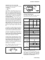
VACION PLUS 20 NOBLE DIODE
Fig. 6 - Pumping speed vs pressure for Nitrogen
Fig. 7 - Pumping speed vs pressure for Argon
Fig. 8 - Pressure vs current diagram
11 87-900-106-01(B)

TECHNICAL INFORMATION
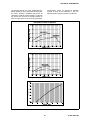
VACION PLUS 20 DIODE
Fig. 9 - Pumping speed vs pressure for Nitrogen
Fig. 10 - Pressure vs current diagram
OUTLINE DRAWING
The following figure shows the outline drawing for the VacIon Plus pump.
Fig. 11 - VacIon Plus pump outline drawing
12 87-900-106-01(B)

TECHNICAL INFORMATION
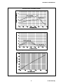
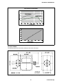
STRAY MAGNETIC FIELD
Curves of stray magnetic field strength along the centre line of the pump and in the plane of the flange as a
function of distance from the pump are shown in Figs. 13, 14 and 15.
Fig. 12 - VacIon Plus pump axis identification
Fig. 13 - Stray magnetic field along X axis
Fig. 14 - Stray magnetic field along Y axis
Fig. 15 - Stray magnetic field along Z axis
13 87-900-106-01(B)

TECHNICAL INFORMATION
VACION PLUS PUMP INSTALLATION
Inspection procedure
VacIon Plus pumps are evacuated, baked out,
sealed and leak-checked at below 1x10
-10
Torr
(mbar) or below prior to shipping. The following
information and procedures can be used to estab-
lish the vacuum integrity of a VacIon Plus pump
before installation.
Visual inspection
Inspect the pump and magnet for physical damage
which may have occurred during shipment. Inspect
the pinch-off seal. If it is open, the pump is at at-
mospheric pressure.
,
WARNING!
The pinch-off seal is extremely sharp. Be careful.
A VacIon Plus pump that has been exposed to at-
mosphere during shipment, or while in storage, will
operate properly if it has otherwise not been dam-
aged.
The pump is not harmed by such exposure, al-
though it is good practice to keep it under vacuum
when not in use to exclude dust and the accumula-
tion of water vapor from the environment.
Vacuum evaluation
The ion pump is shipped in an evacuated condi-
tion. Before removing the shipping flange for in-
stallation on a vacuum system, it is recommended
that the pump be started briefly to verify vacuum
integrity and proper operation.
To verify the vacuum integrity of the new pump be-
fore venting:
1. Connect the pump to the control unit as di-
rected in the instruction manual of the control
unit.
,
WARNING!
The high voltage which is present in the ion pump
from the control unit can cause severe injury or
death.
2. With the main power switch in the OFF posi-
tion, plug the control unit into a suitable power
source.
3. Turn the power to ON.
4. Observe the reading for an indication of one of
the following conditions:
− If the pump is free of leaks and is at a low
pressure, the pressure indication shall within
10 minutes fall to or below the 10
-8
Torr
(mbar) range as the volume of gas is
pumped.
− If the pressure inside the pump is at or near
atmospheric level, an arc may strike inside
the high voltage feedthrough giving a pop-
ping sound and the pump current will fluctu-
ate. If this occurs, turn the power OFF
immediately.
5. If the vacuum integrity has been lost, the pump
should be leak-checked with a mass spec-
trometer leak detector before installation on the
system.
Short circuits
If there is a short circuit between the anode and
cathodes in the pump (or cathode to pump body),
the short-circuit current of the control unit will be
drawn and low voltage will be indicated. If a short
circuit exists in the control unit or high voltage ca-
ble and connector, low voltage will also be ob-
served when the high voltage connector is
disconnected from the pump (refer to the control
unit manuals). An ohm meter reading on the pump
feedthrough may not be effective in finding a short.
Short circuits may be caused by mechanical shock
to the pump. If the pump is shorted, contact Var-
ian.
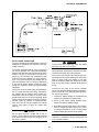
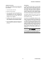
TYPICAL INSTALLATION
A typical installation is shown in Fig. 16 and con-
sists of:
1. VacIon Plus pump.
2. A Valve to seal off the pump from the rest of
the system (if required).
3. The control unit.
4. A clean roughing pump (i.e. turbo).
5. A thermocouple gauge capable of indicating
pressure from atmosphere to 10
-3
Torr/mbar
range.
6. A valve to seal off the roughing pump from the
vacuum chamber. Roughing lines, are usually
made of stainless steel or copper tubing, or
other low vapour pressure material.
7. High voltage cable.
8. Backing pump (diaphragm or scroll).
14 87-900-106-01(B)

TECHNICAL INFORMATION
Fig. 16 - Typical installation
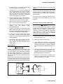
INLET FLANGE CONNECTION
The pump should be mounted allowing a sufficient
clearance for installation and removal of the high
voltage connector.
To achieve good performance of the ion pump at
low vacuum pressure, it is critical that atmospheric
pollution and dust must not enter the pump during
venting. This type of contamination will not be re-
moved by the standard high temperature bake
procedure and may degrade ion pump perform-
ance. The pump should be kept sealed with its
pinch-off tubulation until it is ready for attachment
to the vacuum system. Before venting the pump,
consult the inspection procedure (see preceding
paragraph).
Vent the ion pump by opening the pinch-off tubula-
tion in a clean area free from smog, dust, pollen,
etc. Venting with dry nitrogen gas is further rec-
ommended. This can be done by placing a clean
polyethylene bag over the ion pump flange. Small
pumps can be placed inside of the bag. Purge the
bag with clean, dry nitrogen for several minutes,
then reach into the bag and release the internal
vacuum using pliers to open the copper tube
pinch-off.
CAUTION
Do not open the pinch off-seal with a saw or
grinder. These methods will cause metal particles
to be drawn into the pump by the inrushing air as
the pump is opened.
,
WARNING!
The pinch-off seal is extremely sharp. Be careful
when opening. Watch your fingers.
Use appropriate procedures to maintain the clean
condition of the pump and vacuum system.
Unscrew the main flange bolts. Remove the Con-
Flat flange and the copper gasket plate. Some par-
ticles of copper oxide may adhere to the outer
edge of the flange gasket. Be careful not to allow
them or any other foreign materials to fall into the
pump.
Connect the ion pump to the vacuum chamber
with a short length and large diameter tubulation in
order to retain as much pumping speed as possi-
ble. Proceed as follows:
1. Inspect the mating flanges for cleanliness and
absence of scratches on the knife edge.
2. Place a new copper gasket between pump
flange and vacuum chamber flange.
3. Bolt mating flanges of the pump to the chamber
with the screws provided with the ion pump.
For flanges over NW 35 (2.75" o.d.) also mount
washers below the nuts and screw heads.
NOTE
Lubrication is essential to prevent galling of the nut
and screw after bakeout.
15 87-900-106-01(B)
La pagina si sta caricando...
La pagina si sta caricando...
La pagina si sta caricando...
La pagina si sta caricando...
La pagina si sta caricando...
La pagina si sta caricando...
La pagina si sta caricando...
La pagina si sta caricando...
La pagina si sta caricando...
La pagina si sta caricando...
-
 1
1
-
 2
2
-
 3
3
-
 4
4
-
 5
5
-
 6
6
-
 7
7
-
 8
8
-
 9
9
-
 10
10
-
 11
11
-
 12
12
-
 13
13
-
 14
14
-
 15
15
-
 16
16
-
 17
17
-
 18
18
-
 19
19
-
 20
20
-
 21
21
-
 22
22
-
 23
23
-
 24
24
-
 25
25
-
 26
26
-
 27
27
-
 28
28
-
 29
29
-
 30
30


Varian 919-1145 Manuale utente
- Tipo
- Manuale utente
in altre lingue
- English: Varian 919-1145 User manual
- français: Varian 919-1145 Manuel utilisateur
Documenti correlati
-
Varian MidiVac 929-5001 Manuale utente
-
-
-
-
-
Varian 969-9125 Instructions For Use Manual
-
-
-
-