Vitek VT-PTZ10T LEGACY Manuale utente
- Categoria
- Telecamere di sicurezza
- Tipo
- Manuale utente
Questo manuale è adatto anche per

VITEK
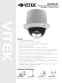
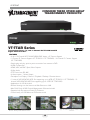
VT-PTZ10T
Compact HD-TVI/CVBS PTZ Camera
with WDR & 10x Optical Zoom
VT-PT12/CMT
VT-PTZ10T Pedestal
Ceiling Mount
VT-MD/WMT
Mighty Dome /
VT-PTZ10T Wall Mount
VT-MD/PLMT
Mighty Dome /
VT-PTZ12 Pole Mount
Adapter
VT-MD/CNMT
Mighty Dome /
VT-PTZ12 Corner Mount
Adapter
• 1/3” Panasonic CMOS Sensor
• 2.1 MegaPixel HD-TVI / 700TVL CVBS Output
• Built-In 5.1 to 51mm Lens with 10x Optical / 32x Digital Zoom
• True Day/Night function with ICR
• 128 Presets programmed with view direction, zoom, and BLC
• 8 Patterns record and play back user preference of surveillance path up to 120º sec.
• 8 Scans: 8 speed steps from slow to medium panning with smooth Diagonal Scan
• 4 Tours: Each tour consists up to 32 Presets, Patterns, and/or Scans
• 4 Alarm inputs with 1~4 priority / 1 Auxiliary output with programmable NC & NO
• 8 Privacy Zones: Video off or up to 8 masked blocks
• 64 steps of variable speed from 0.4º/sec to 90º/ sec. Max manual speed 190º/sec
with Turbo key pressed, Preset speed is 380º/sec.
• Built-in RS-485 receiver driver, power-line surge lightning protection, Heater/Blower
for use in Extreme Temperatures
• Wide Dynamic Range (WDR) accurately captures clear images even in scenes that
contain both very bright and very dark areas
• IP 67 with optional Mounting bracket
FEATURES
OPTIONAL ACCESSORIES:

1 2
VT-PTZ10T
UNPACKING
Before installing the Dome camera, please make sure that the following items are
included in the box:
1. Mini Speed Dome Camera
2. Instruction Manual
3. Mounting Hardware
If any of these materials are missing, please contact the vendor or VITEK customer help
desk immediately.

2
VT-PTZ10T
DISCLAIMER
• While every effort has been made to ensure that the information contained in this
guide is accurate and complete, no liability can be accepted for any errors or
omissions.
• VITEK reserves the right to change the specifications of the hardware and software
described herein at any time without prior notice.
• No part of this guide may be reproduced, transmitted, transcribed, stored in a
retrieval system, or translated into any language in any form, by any means, without
prior written permission of VITEK.
• VITEK makes no warranties for damages resulting from corrupted or lost data due to
a mistaken operation or malfunction of the Speed Dome Cameras, peripheral
devices, or unapproved/unsupported devices.

3 4
VT-PTZ10T
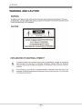
WARNING AND CAUTION

4
VT-PTZ10T
FCC COMPLIANCE STATEMENT
CE COMPLIANCE STATEMENT
FCC INFORMATION: THIS EQUIPMENT HAS BEEN TESTED AND FOUND TO
COMPLY WITH THE LIMITS FOR A CLASS A DIGITAL DEVICE, PURSUANT TO
PART 15 OF THE FCC RULES. THESE LIMITS ARE DESIGNED TO PROVIDE
REASONABLE PROTECTION AGAINST HARMFUL INTERFERENCE WHEN
THE EQUIPMENT IS OPERATED IN A COMMERCIAL ENVIRONMENT. THIS
EQUIPMENT GENERATES, USES, AND CAN RADIATE RADIO FREQUENCY
ENERGY AND IF NOT INSTALLED AND USED IN ACCORDANCE WITH THE
INSTRUCTION MANUAL, MAY CAUSE HARMFUL INTERFERENCE TO RADIO
COMMUNICATIONS. OPERATION OF THIS EQUIPMENT IN A RESIDENTIAL
AREA IS LIKELY TO CAUSE HARMFUL INTERFERENCE IN WHICH CASE THE
USER WILL BE REQUIRED TO CORRECT THE INTERFERENCE AT HIS OWN
EXPENSE.
CAUTION: CHANGES OR MODIFICATIONS NOT EXPRESSLY APPROVED BY
THE PARTY RESPONSIBLE FOR COMPLIANCE COULD VOID THE USER'S
AUTHORITY TO OPERATE THE EQUIPMENT.
THIS CLASS A DIGITAL EQUIPMENT COMPLIES WITH CANADIAN ICES-003.
CET APPAREIL NUMÉRIQUE DE LA CLASSE A EST CONFORME À LA NORME
NMB-003 DU CANADA.
WARNING
THIS IS A CLASS A PRODUCT. IN A DOMESTIC ENVIRONMENT THIS
PRODUCT MAY CAUSE RADIO INTERFERENCE IN WHICH CASE THE USER
MAY BE REQUIRED TO TAKE ADEQUATE MEASURES.

5 6
VT-PTZ10T
IMPORTANT SAFEGUARDS
1. Read these instructions.
2. Heed all warnings.
3. Follow all instructions.
4. Do not use this equipment near water.
5. Clean only with dry cloth.
6. Do not block any ventilation openings. Install in accordance with the manufacturer's
instructions.
7. Do not install near any heat sources such as radiators, heat registers, stoves, or
other equipment (including amplifiers) that produce heat.
8. Do not defeat the safety purpose of the polarized or grounding-type plug. A
polarized plug has two blades with one wider than the other. A grounding type plug
has two blades and a third grounding prong. The wide blade or the third prong is
provided for your safety. If the provided plug does not fit into your outlet, consult an
electrician for replacement of the obsolete outlet.
9. Protect the power cord from being walked on or pinched, particularly at plugs,
convenience receptacles, and the point where they exit from the equipment.
10. Only use attachments/accessories specified by the manufacturer.
11. Unplug this equipment during lightning storms or when unused for long periods of
time.
12. Refer all servicing to qualified service personnel. Servicing is required when the
equipment has been damaged in any way, such as power-supply cord or plug is
damaged, liquid has been spilled or objects have fallen into the equipment, the
equipment has been exposed to rain or moisture, does not operate normally, or has
been dropped.
13. CAUTION - THESE SERVICING INSTRUCTIONS ARE FOR USE BY QUALIFIED
SERVICE PERSONNEL ONLY. TO REDUCE THE RISK OF ELECTRIC SHOCK
DO NOT PERFORM ANY SERVICING OTHER THAN THAT CONTAINED IN THE
OPERATING INSTRUCTIONS UNLESS YOU ARE QUALIFIED TO DO SO.
Use Certified/Listed Class 2 power supply transformer only.

6
VT-PTZ10T
TABLE OF CONTENTS
ABLE OF CONTENTS
DISCLAIMER ................................................................................................................... 1
I. INTRODUCTION .......................................................................................................... 6
Features .................................................................................................................................................. 6
II. INSTALLATION AND CONFIGURATION ................................................................... 7
2.1 Typical System Configuration ........................................................................................................ 7
2.2 Basic Configuration of Speed Dome Camera System .................................................................. 8
2.3 Connecting the Speed Dome directly into the DVR ...................................................................... 9
2.4 Connecting the Speed Dome into the Controller via J-box ......................................................... 9
2.5 Connecting Both Speed Dome and DVR via J-box ..................................................................... 10
2.6 Setting Video Out ........................................................................................................................... 12
2.7 Principle of Termination ................................................................................................................ 12
2.8 Dome Camera Address (ID) .......................................................................................................... 14
2.9 Setting Protocols ........................................................................................................................... 14
2.9 Connections ................................................................................................................................... 15
2.10 Mounting the Dome Camera ....................................................................................................... 16
2.11 Power on and Boot-up Sequence ............................................................................................... 17
III. PROGRAM & OPERATION ...................................................................................... 18
Dome Camera Selection ...................................................................................................................... 18
3.1 FUNCTIONS .................................................................................................................................... 18
3.1.1 HOME FUNCTION (MENU =>FUNCTIONS => HOME FUNCTION) ................................................................................. 19
3.1.2 PRESET (MENU => FUNCTIONS => PRESET Short Cut: PRST) ................................................................................... 20
3.1.3 SCAN (MENU => FUNCTIONS => SCAN or Shortcut: SCAN) ......................................................................................... 22
3.3 SCREEN .......................................................................................................................................... 27
3.3.1 LANGUAGE (MENU => SCREEN => LANGUAGE) ......................................................................................................... 27
3.3.2 NORTH DIRECTION (MENU => SCREEN => NORTH DIRECTION) .............................................................................. 28
3.4 CAMERA (MENU => CAMERA) ..................................................................................................... 30
3.4.1 FOCUS CONTROL (MENU => CAMERA => FOCUS CONTROL) .................................................................................. 30
3.4.2 WB (white balance) (MENU => CAMERA => WB CONTROL) ......................................................................................... 30
3.4.3 EXPOSURE SETUP (MENU => CAMERA => EXPOSURE SETUP) .............................................................................. 31
3.4.4 BLC/WDR (MENU è CAMERA èBLC/WDR) ................................................................................................................. 31
3.4.5 DEFOG (MENU è CAMERA èDEFOG) ......................................................................................................................... 31
3.4.6 SHARPENSS CONTROL (MENU => CAMERA =>SHAPENESS) ................................................................................... 32
3.4.7 DIGITAL ZOOM (MENU => CAMERA =>DIGITAL ZOOM) .............................................................................................. 32
3.4.8 NIGHT SHOT MENU (MENU => CAMERA =>NIGHT SHOT) .......................................................................................... 32
3.4.9 DIS (MENU => CAMERA =>DIS (Digital Image Stabilization)) ......................................................................................... 32
3.4.10 CAMERA INITIALIZE (MENU => CAMERA =>CAMERA INITIALIZE) ........................................................................... 32
3.5 SETUP (MENU => SETUP)............................................................................................................. 33
3.5.1 FLIP (MENU => SETUP => FLIP) ...................................................................................................................................... 33
3.5.2 SPEED (MENU => SETUP => SPEED) ............................................................................................................................. 33
3.5.3 PRESET FREEZE (MENU => SETUP => PRESET FREEZE) .......................................................................................... 33
3.5.4 PANNING RANGE (MENU => SETUP => PANNING RANGE) ......................................................................................... 34
3.5.5 TILT LIMIT (MENU => SETUP => TILT LIMIT) .................................................................................................................. 34
3.5.6 CALIBRATION (MENU => SETUP => CALIBRATION) ..................................................................................................... 34
3.5.7 RESOLUTION (MENU => SETUP => RESOLUTION) ....................................................................................................... 35
3.5.8 FACTORY DEFAULT (MENU => SETUP => FACTORY DEFAULT) ................................................................................ 35
3.5.9 ERASE DATA (MENU => SETUP => ERASE DATA) ........................................................................................................ 35
3.5.10 SYSTEM INFORMATION (MENU => SETUP => SYSTEM INFORMATION) ................................................................. 35
Appendix A — Troubleshooting ................................................................................. 37
Glossary ........................................................................................................................ 38

7 8
VT-PTZ10T
I. INTRODUCTION
Features
The Speed Dome Camera features a high resolution 1/3” CMOS imager for enhanced
lowlight sensitivity. User friendly, on-screen pull-down menus and short-cuts make it
easy to setup and program functions.
System information aides trouble shooting by displaying the hardware and software
version of the camera’s firmware version, baud rate, and protocol.
• Built-in 10X times Optical Zoom Camera.
True Night Shot function with ICR Day/Night function.
• Digital Image Stabilization function.
• 128 Presets programmed with view direction, zoom, and BLC & WDR.
• 8 Scans: 8 speed steps from slow to medium panning with smooth DiagonalScan.
• 4 Tours: Each tour consists up to 32 Preset, Pattern, or Scans.
Smooth DiagonalScan mode and programmable Individual dwell time camera
functions.
• 4 Alarm inputs with 1~4 priority / 1 Auxiliary outputs programmable NC & NO.
• 64 steps of variable speed from 0.4°/sec to 140°/sec.
Max manual speed 190°/sec with Turbo key pressed, Preset speed is 380°/sec.
• Programmable user preferences of speed (Slow, Medium, and Fast).
• Addressable up to 99 camera IDs (Extendable up to 3999 in special mode).
• Built-in RS-485 receiver driver.
• On-site software upgrade and upload/download of programmed data into the
KBD/Dome.
• Built-in power-line surge protection and lightning protection.
• Optional Tinted Bubble, Indoor & Outdoor pendant housing, Heater & Blower.
Flush Mount Kit

8
VT-PTZ10T
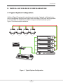
II. INSTALLATION AND CONFIGURATION
2.1 Typical System Configuration
Additional Speed Dome joystick controllers and a variety of external switching devices
such as multiplexers (MUXes) and Digital Video Recorders (DVRs) may be incorporated
to accommodate the needs from a small to a large surveillance/security system.
Figure 1 illustrates sample installation.
Figure 1 - Typical System Configuration

9 10
VT-PTZ10T
STP AWG # 22
VIDEO
BNC MONITOR
AC 24V
POWER
HALF DUPLEX MODE
TRX-
TRX+
TRX+
TRX-
CONTROLLER
DOME
POWER
AC 24V
AC 24V
HEATER
1 AUX OUTPUT
4 ALARM INPUT
COMM.(TRX+/TRX-)
RS-485
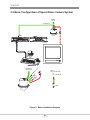
2.2 Basic Configuration of Speed Dome Camera System
Figure 2 - Basic Installation Diagram

10
VT-PTZ10T
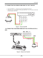
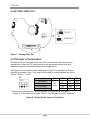
2.3 CONNECTING THE SPEED DOME DIRECTLY INTO THE DVR
• Locate the RS485 + & - conductor wire from the Speed Dome Camera.
• Connect the + & - into the TRX+ & TRX- ports of the DVR. Tx+ & Tx- ports can be found
on the rear panel of the DVR.
Figure 3 - Camera into DVR
2.4 CONNECTING THE SPEED DOME INTO THE CONTROLLER VIA J-
BOX
Figure 4 - Camera into Controller

11 12
VT-PTZ10T
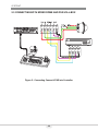
2.5 CONNECTING BOTH SPEED DOME AND DVR VIA J-BOX
Figure 5 - Connecting Camera & DVR into Controller

12
VT-PTZ10T
Video
Power AC 24V~
Comm.(RX/TX)
Heater AC 24V~
1 Aux Output
4 Alarm Input
Fan
1
2
3
4
5
6
7
8
9
0
S2
S1
9
8
7
6
5
4
3
2
0
1
Selection Switches
S4 S3S5
Address(ID)
Termination
Protocol
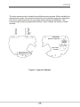
The dome camera must be installed by qualified service personnel. Before installing the
dome camera system, this instruction manual must be read thoroughly and understood
fully. Dome cameras must be set up properly before starting the installation. This
involves properly setting configuration switches. Figure 6 shows the location of these
switches.
Figure 6 - Layout of Switches

13 14
VT-PTZ10T
2.6 SETTING VIDEO OUT
HD
1 3
SD
1 3
TVI OUT
CVBS OUT
SD
HD
1 3
Figure 7 - Setting Video Out
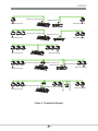
2.7 Principle of Termination
The device that is connected at the end of the communication data line must be
terminated by either the DIP switch setting or an appropriate device such as a
termination jumper to prevent potential control signal errors.
See Figure 8 for termination switch settings and Figure 9 for examples of devices
requiring termination. Note: Total length of the cable for communication should not
exceed 1.2Km or .74 mile.
** Unless communication error, put the position 2, 3 of the S5 in OFF state.
Position 2, 3 should be set as a pair. (Both 2, 3 to ON position or OFF position)
Figure 8 - Setting Dome Camera Termination
S5
D1
D2
D3
D4
Terminated
Not
Used
X
X
ON
Not terminated
X
X
OFF
Pull Up/Down **
ON
ON
X
Normal **
OFF
OFF
X

14
VT-PTZ10T
Figure 9 - Termination Diagram
SW1:Termination ON
SW!:Termination ON
TERMINATION ON
SW1:Termination ON
DVR Termination ON
S1:Dome1 port Termination ON
S1:Dome1 port Termination ON
SW1:Termination ON SW1:Termination ON
DVR Termination ON
SW1:Termination ONSW1:Termination ON
SW1:Termination ON
SW1:Termination ON
S1:Dome1 port Termination ON
S4:DVR port Termination ON
DVR Termination ON
DVR Termination ON
SW1:Termination ON
S1:Dome1 port Termination ON
S3:Dome2 port Termination ON
SW1:Termination ON

15 16
VT-PTZ10T
1
2
3
4
5
6
7
8
9
0
S2
S1
S3
S4
3
2
6
5
4
8
7
9
1
0
on
on
D1 D4 D5 D8
.. ..
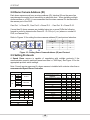
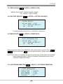
2.8 Dome Camera Address (ID)
Each dome camera must have a unique address (ID). Identical IDs on the same line
may damage the control circuit caused by an electrical short. When installing multiple
dome cameras or a DVR, it is recommended that the dome camera ID’s be identical to
the camera port of the DVR.
Cam Port 1 = Dome ID1, Cam Port 2 = Dome ID 2 … Cam Port 16 = Dome ID 16.
If more than 16 dome cameras are installed using two or more DVRs the following
formula is useful to determine the Dome ID: ID =16x (n-1) +m (where n= number of
DVR, m=Camera Port)
Refer to Figures 10 for setting the dome camera address (ID) and protocol selection.
Figure 10 - Setting Dome Camera Address (ID) and Protocol
2.9 Setting Protocols
A Speed Dome camera is capable of negotiating with multiple protocols if the
communication speed is matched (same baud rate i.e., 9600 bps). See Figure 10 for the
appropriate protocol switch settings.
Note: Consult service personnel if a dome camera is installed with a device other than a
recommended Speed Dome Controller.
Dip S/W
Function
S4
D1
Protocol
D2
D3
D4
S3
D5
Baud Rate
D6
D7
D8
Extended ID
Protocol
D1
D2
D3
D4
AUTO Selection(no parity)
DEFAULT
Off Off Off Off
AUTO selection(even parity)
On
Off
Off
Off
PP
Off
On
Off
Off
EZ
On
On
Off
Off
S2
Off
Off
On
Off
PD
On
Off
On
Off
VC
Off
On
On
Off
SN
On
On
On
Off
DC
Off
Off
Off
On
Reserved
On
Off
Off
On
PPS
Off
On
Off
On
Reserved
On
On
Off
On
Reserved
Off
Off
On
On
VVL
On
Off
On
On
DDI
Off
On
On
On
Reset
On
On
On
On
Baud Rate
D5
D6
D7
2400 bps
Off
Off
Off
4800 bps
Off
Off
ON
9600 bps
Off
ON
Off
19200 bps
Off
ON
ON
38400 bps
ON
Off
Off
VIDEO
D8
NTSC
Off
PAL
On
for setting the dome camera address (ID)
protocol
DOME ID
S2
S1
1
0
1
.
.
.
99
9
9

16
VT-PTZ10T
Figure 11 - Protocol Selection tables
2.9 Connections
• How to Connect RS485
The dome camera has a built-in RS-485 receiver so that it can be controlled
remotely by an external control device such as a joystick controller or a DVR.
RS-485: Connect the TXA (Tx+) and TXB (Tx-) of the RS485 control devices
(KBD, DVR…) to TRX+, TRX- of the dome camera.
RS-485 does not allow for a star connection layout. A splitter is required if a
star connection layout is desired. RS-485 guarantees 1.2 Km of data line
routing. A repeater is recommended to extend over 1.2 Km.
• Connecting Alarms
AL1 to 4 (Alarm In)
Magnetic, PIR or other external sensor devices can be used to signal the
dome camera reacting to an event.
See Chapter 3.2 — Program and Operation for configuring alarm input.
GND (Ground)
NOTE: All the connectors marked GND are common.
Connect the ground of the Alarm input and/or alarm output to the GND
connector.
NO / NC (Normally Opened or Normally Closed dry contact relay output)
The dome camera can activate external devices such as buzzers or lights
using dry contact relays. Connect the device to the NO (NC) (Alarm Out) and
COM (Common) connectors. See Chapter 3 — Program and Operation for
configuring alarm output.
• Connecting the Power
Connect AC 24V 40VA power to the dome camera.
Use certified / Listed Class 2 power supply transformer only.

17 18
VT-PTZ10T
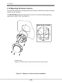
2.10 Mounting the Dome Camera
Once all DIP switches are set properly and all external connections are made, the dome
camera can be mounted.
The Mini PTZ Dome camera is designed to mount on a structural body supporting
loads up to 6.6Lbs / 3 Kg. See Figure 12.
Figure 12 - Example of a flush mounted installation
Installation Hint
Using Four ST4X30 screws, attach flush mount base to sturdy surface

18
VT-PTZ10T
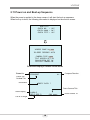
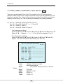
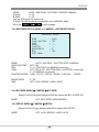
2.11 Power on and Boot-up Sequence
When the power is applied to the dome camera, it will start the boot-up sequence.
When boot-up is done, the following information is displayed on the monitor screen.
On Screen Display in normal control mode
RAM TEST
CHECK NO. : OK!
CHECK AAAA : OK!
CHECK 5555 : OK!
XPRESS DOME Vx.xxx
ID:0001 9600BPS AUTO
CAMERA TYPE xxxx
TILT ORIGIN SET OK
PAN ORIGIN SET OK
INITIAL CAMERA OK
001PRESET W→
EMPTY DATA !
ALARM:1
360.0,090.0 CAM xxxx
Preset No.
Information
Alarm Display
Dome Camera Title
Dome Camera ID
Compass Direction
Pan & Tilt Angle
Preset Title
Or Area Title

19 20
VT-PTZ10T
III. PROGRAM & OPERATION
Dome Camera Selection
Prior to programming or operating a dome camera, please make sure that both the
camera and the joystick controller are communicating. In order for changes to take
effect for a camera, particular camera’s ID must be selected on the controller.
Example: Pressing 1 , 6 and CAM key sequentially will select dome camera 16. The
selected dome camera ID will be displayed on the monitor.
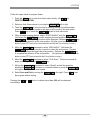
Principle of joystick usage in the programming (editing) mode
Button or Joystick movement in menu
Function
Joystick left or right
Go into the sub-menu items.
Execute the command(exit)
Change value.
Navigate through the menu items.
Joystick
up or down
Navigate through the menu items.
Joystick
down
Finish editing title.
Zoom handle twist
Change value.(Increase / Decrease)
Enter editing title mode.
SHFT + Joystick
PTZ control mode.
ESC
Escape from the menu without change.
Home or Off button
Delete value or name of the field.
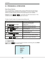
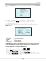
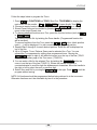
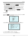
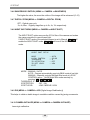
3.1 FUNCTIONS
By pressing the MENU button on the keyboard controller, the following On-screen MAIN
MENU will be shown on the monitor screen.
MAIN MENU
FUNCTION
ALARM
SCREEN
CAMERA
SETUP
EXIT
La pagina si sta caricando...
La pagina si sta caricando...
La pagina si sta caricando...
La pagina si sta caricando...
La pagina si sta caricando...
La pagina si sta caricando...
La pagina si sta caricando...
La pagina si sta caricando...
La pagina si sta caricando...
La pagina si sta caricando...
La pagina si sta caricando...
La pagina si sta caricando...
La pagina si sta caricando...
La pagina si sta caricando...
La pagina si sta caricando...
La pagina si sta caricando...
La pagina si sta caricando...
La pagina si sta caricando...
La pagina si sta caricando...
La pagina si sta caricando...
La pagina si sta caricando...
La pagina si sta caricando...
La pagina si sta caricando...
La pagina si sta caricando...
-
 1
1
-
 2
2
-
 3
3
-
 4
4
-
 5
5
-
 6
6
-
 7
7
-
 8
8
-
 9
9
-
 10
10
-
 11
11
-
 12
12
-
 13
13
-
 14
14
-
 15
15
-
 16
16
-
 17
17
-
 18
18
-
 19
19
-
 20
20
-
 21
21
-
 22
22
-
 23
23
-
 24
24
-
 25
25
-
 26
26
-
 27
27
-
 28
28
-
 29
29
-
 30
30
-
 31
31
-
 32
32
-
 33
33
-
 34
34
-
 35
35
-
 36
36
-
 37
37
-
 38
38
-
 39
39
-
 40
40
-
 41
41
-
 42
42
-
 43
43
-
 44
44


Vitek VT-PTZ10T LEGACY Manuale utente
- Categoria
- Telecamere di sicurezza
- Tipo
- Manuale utente
- Questo manuale è adatto anche per
in altre lingue
- English: Vitek VT-PTZ10T LEGACY User manual
Documenti correlati
Altri documenti
-
Samsung SCC-C7478CP Manuale utente
-
-
-
Samsung SCC-C6323P Manuale utente
-
Samsung SCC-C6455 Manuale utente
-
-
-
-
Elvox Telecamera speed dome IR Speed Dome Istruzioni per l'uso
-
Comelit AHPTZ120A Manuale utente