Vitek VT-PTZ40WH Manuale utente
- Categoria
- Telecamere di sicurezza
- Tipo
- Manuale utente

VITEK
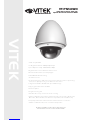
VT-PTZ40WH
960H Xpress Dome with 40X
Optical Zoom and Advanced WDR
• 1/2.9” Sony® CMOS
• 2.1 MegaPixel With full 1080p/720p Output
• Up to 30fps live view@ 1920x1080 (1080p)
• MegaPixel IR Corrected 9-22mm Varifocal Lens
• Mechanical IR Cut Filter (True Day/Night)
• H.264/MJPEG Dual Streaming
• 16:9 Video format
• On-board Intelligence (OBI Technology) delivers Auto-Focus-Zoom by tracking
motion, then optically zooming in to that area of the frame
• 6 High Power 850nm IR LEDs with up to 300’ IR range
• Fully programmable advanced WDR
• Onvif Compliance
• Integrated Cooling Fan
• Standard SD memory card slot for Local recording
• Advanced OSD Functions: Motion Activated Pointing Zoom, Defog, Dynamic IR,
BLC/HLC, Motion Deblur, Pixel Defect Compensation, Title Set, Mirror, Flip
• Heavy Duty IP68 rated weather/vandal resistant aluminum construction
• 12VDC / 24VAC & PoE (Power over Ethernet) Operation
Specifications & installation procedure subject to change without notice.
Visit www.vitekcctv.com for the most current information available.

VT-PTZ Series
1
DISCLAIMER
• While every effort has been made to ensure that the information contained in this guide
is accurate and complete, no liability can be accepted for any errors or omissions.
• Vitek reserves the right to change the specifications of the hardware and software
described herein at any time without prior notice.
• No part of this guide may be reproduced, transmitted, transcribed, stored in a retrieval
system, or translated into any language in any form, by any means, without prior written
permission of Vitek.
• Vitek makes no warranties for damages resulting from corrupted or lost data due to a
mistaken operation or malfunction of the Speed Dome Cameras, peripheral devices, or
unapproved/unsupported devices.

VT-PTZ Series
2
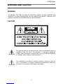
WARNING AND CAUTION
WARNING
TO REDUCE THE RISK OF FIRE OR ELECTRIC SHOCK, DO NOT EXPOSE THIS
PRODUCT TO RAIN OR MOISTURE. DO NOT INSERT ANY OBJECT THROUGH THE
VENTILATION GRILLS OR OPENINGS ON THE EQUIPMENT.
CAUTION
The lightning flash with arrowhead symbol, within an equilateral triangle, is
intended to alert the user to the presence of uninsulated “dangerous
voltage” within the product’s enclosure that may be of sufficient magnitude
to constitute a risk of electric shock to persons.
The exclamation point within an equilateral triangle is intended to alert the
user to the presence of important operating and maintenance (servicing)
instruction in the literature accompanying the product.

VT-PTZ Series
3
FCC COMPLIANCE STATEMENT
CE COMPLIANCE STATEMENT
FCC INFORMATION: THIS EQUIPMENT HAS BEEN TESTED AND FOUND TO
COMPLY WITH THE LIMITS FOR A CLASS A DIGITAL DEVICE, PURSUANT TO
PART 15 OF THE FCC RULES. THESE LIMITS ARE DESIGNED TO PROVIDE
REASONABLE PROTECTION AGAINST HARMFUL INTERFERENCE WHEN
THE EQUIPMENT IS OPERATED IN A COMMERCIAL ENVIRONMENT. THIS
EQUIPMENT GENERATES, USES, AND CAN RADIATE RADIO FREQUENCY
ENERGY AND IF NOT INSTALLED AND USED IN ACCORDANCE WITH THE
INSTRUCTION MANUAL, MAY CAUSE HARMFUL INTERFERENCE TO RADIO
COMMUNICATIONS. OPERATION OF THIS EQUIPMENT IN A RESIDENTIAL
AREA IS LIKELY TO CAUSE HARMFUL INTERFERENCE IN WHICH CASE THE
USER WILL BE REQUIRED TO CORRECT THE INTERFERENCE AT HIS OWN
EXPENSE.
CAUTION: CHANGES OR MODIFICATIONS NOT EXPRESSLY APPROVED BY
THE PARTY RESPONSIBLE FOR COMPLIANCE COULD VOID THE USER'S
AUTHORITY TO OPERATE THE EQUIPMENT.
THIS CLASS A DIGITAL EQUIPMENT COMPLIES WITH CANADIAN ICES-003.
CET APPAREIL NUMÉRIQUE DE LA CLASSE A EST CONFORME À LA
NORME NMB-003 DU CANADA.
WARNING
THIS IS A CLASS A PRODUCT. IN A DOMESTIC ENVIRONMENT THIS
PRODUCT MAY CAUSE RADIO INTERFERENCE IN WHICH CASE THE USER
MAY BE REQUIRED TO TAKE ADEQUATE MEASURES.

VT-PTZ Series
4
IMPORTANT SAFEGUARDS
1. Read these instructions.
2. Heed all warnings.
3. Follow all instructions.
4. Do not use this equipment near water.
5. Clean only with dry cloth.
6. Do not block any ventilation openings. Install in accordance with the manufacturer's
instructions.
7. Do not install near any heat sources such as radiators, heat registers, stoves, or other
equipment (including amplifiers) that produce heat.
8. Do not defeat the safety purpose of the polarized or grounding-type plug. A polarized
plug has two blades with one wider than the other. A grounding type plug has two
blades and a third grounding prong. The wide blade or the third prong is provided for
your safety. If the provided plug does not fit into your outlet, consult an electrician for
replacement of the obsolete outlet.
9. Protect the power cord from being walked on or pinched, particularly at plugs,
convenience receptacles, and the point where they exit from the equipment.
10. Only use attachments/accessories specified by the manufacturer.
11. Unplug this equipment during lightning storms or when unused for long periods of
time.
12. Refer all servicing to qualified service personnel. Servicing is required when the
equipment has been damaged in any way, such as power-supply cord or plug is
damaged, liquid has been spilled or objects have fallen into the equipment, the
equipment has been exposed to rain or moisture, does not operate normally, or has
been dropped.
13. CAUTION - THESE SERVICING INSTRUCTIONS ARE FOR USE BY QUALIFIED
SERVICE PERSONNEL ONLY. TO REDUCE THE RISK OF ELECTRIC SHOCK
DO NOT PERFORM ANY SERVICING OTHER THAN THAT CONTAINED IN THE
OPERATING INSTRUCTIONS UNLESS YOU ARE QUALIFIED TO DO SO.
14. Use Certified/Listed Class 2 power supply transformer only.

VT-PTZ Series
5
TABLE OF CONTENTS
DISCLAIMER_________________________________________________________1
WARNING AND CAUTION___________________________________________________2
FCC COMPLIANCE STATEMENT_____________________________________________3
CE COMPLIANCE STATEMENT______________________________________________3
IMPORTANT SAFEGUARDS_________________________________________________4
CONTENT VERIFICATION __________________________________________________7
MENU TREE _____________________________________________________________8
INTRODUCTION__________________________________________________________9
INSTALLATION AND CONFIGURATION______________________________________10
Typical system configuration _____________________________________________10
Basic configuration of speed dome camera system____________________________11
Connecting the Speed Dome directly into the DVR____________________________12
Connecting the Speed Dome into the Controller via j-box_______________________12
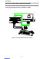
Connecting both Speed Dome and DVR via J-BOX___________________________13
Setting the Video System________________________________________________14
Setting the Web Baudrate_______________________________________________15
Principle of Termination_________________________________________________15
Dome Camera Address (ID) _____________________________________________17
Setting Protocols______________________________________________________18
Connections__________________________________________________________19
Mounting the Dome Camera_____________________________________________20
Power on and Boot-up Sequence_________________________________________21
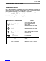
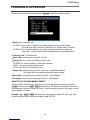
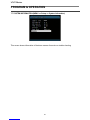
PROGRAM & OPERATION_________________________________________________22
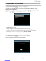
Dome Camera Selection________________________________________________22
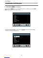
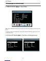
1 FUNCTIONS_______________________________________________________23
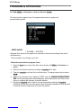
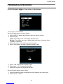
1.1 Home Function___________________________________________________24
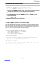
1.2 Preset__________________________________________________________25
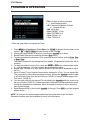
1.3 Scan___________________________________________________________29
1.4 Tour____________________________________________________________30
1.5 Pattern__________________________________________________________32
1.6 Run Function_____________________________________________________32
2 ACTIONS SETUP____________________________________________________33
2.1 Alarm Action Setup________________________________________________33
2.2 Alarm List_______________________________________________________34
2.3 Clear Alarm List__________________________________________________35
2.4 Schedule Action Setup_____________________________________________35
2.5 List Action_______________________________________________________38
3 SCREEN___________________________________________________________39
3.1 Language Setup__________________________________________________39
3.2 Privacy Zone Setup________________________________________________40
3.3 North Direction___________________________________________________40

VT-PTZ Series
6
TABLE OF CONTENTS
3.4 Zone Title_______________________________________________________41
3.5 Camera Title_____________________________________________________42
3.6 OSD Display_____________________________________________________42
4 CAMERA SETUP____________________________________________________43
4.1 Focus Control____________________________________________________43
4.2 WB (white balance) _______________________________________________43
4.3 AE Control______________________________________________________45
4.4 Night Shot Menu__________________________________________________46
4.5 Camera Default__________________________________________________46
5 TIME & DATE SETUP________________________________________________47
5.1 Edit Daylight Savings______________________________________________47
5.2 Edit Holidays_____________________________________________________48
5.3 List Holiday______________________________________________________49
6 DATA SETUP_______________________________________________________50
6.1 Factory Default___________________________________________________50
6.2 Erase Programmed Data___________________________________________51
6.3 Backup Data_____________________________________________________51
6.4 Restore Data____________________________________________________52
6.5 Clear Data______________________________________________________52
7 SETUP____________________________________________________________53
7.1 Preset Freeze____________________________________________________53
7.2 Speed_________________________________________________________53
7.3 Response_______________________________________________________53
7.4 Dome Angle___________________________________________________53
7.4.1 Flip________________________________________________________54
7.4.2 Panning Range_______________________________________________54
7.4.3 Tilt Over Angle________________________________________________54
7.5 Calibration______________________________________________________55
7.6 Password Setup__________________________________________________56
7.7 System Information_______________________________________________57
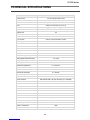
TECHNICAL SPECIFICATIONS_____________________________________________58
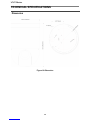
Dimension___________________________________________________________59
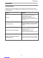
APPENDIX ______________________________________________________________60
Troubleshooting_______________________________________________________60

VT-PTZ Series
7
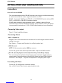
CONTENT VERIFICATION
Before installing the Xpress Dome PTZ Camera, please make sure that the following items
are included in the box:
1. One Xpress Dome Camera
2. One Instruction Manual
3. Three Mounting Screws.
4. Three Plastic Anchors.
5. Two Eight-Pin Cable Assemblies.
If any of these materials are missing, please contact the vendor or Vitek customer help
desk immediately.

VT-PTZ Series
8
MENU TREE
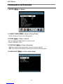
1. FUNCTIONS
1.1 HOME FUNCTION (MENU
!
Functions
!
Home)
1.2 PRESET (MENU
!
Functions
!
Preset Shortcut : PRST)
1.3 PATTERN (MENU
!
Function
!
Pattern or Shortcut: PTRN)
1.4 SCAN (MENU
!
Functions
!
Scan or Shortcut: SCAN)
1.5 TOUR (MENU
!
Functions
!
Tour, Shortcut: TOUR)
1.6 RUN FUNCTION (MENU
!
Functions
!
Run Function)
2. ACTIONS
2.1 ALARM (MENU
!
Actions => Alarm)
2.2 ALARM LIST (MENU
!
Actions
!
Alarm List)
2.3 CLEAR ALARM LIST (MENU
!
Actions
!
Clear Alarm List)
2.4 SCHEDULE (MENU
!
Actions
!
Schedule)
2.5 SCHEDULE LIST (MENU
!
Actions
!
Schedule List)
3. SCREEN
3.1 LANGUAGE (MENU
!
Screen
!
Language)
3.2 PRIVACY ZONE (MENU
!
Screen
!
Privacy Zone)
3.3 NORTH DIRECTION (MENU
!
Screen
!
North Direction)
3.4 ZONE TITLE (MENU
!
Screen
!
Zone Title)
3.5 CAMERA TITLE (MENU
!
Screen
!
Camera Title)
3.6 OSD DISPLAY (MENU
!
Screen
!
OSD Display)
4. CAMERA
4.1 FOCUS CONTROL (MENU
!
Camera
!
Focus Control)
4.2 WB (white balance) (MENU
!
Camera
!
WB Control)
4.3 AE CONTROL (MENU
!
Camera
!
AE Control)
4.4 NIGHT SHOT (MENU
!
Camera
!
Night Shot)
4.5 CAMERA DEFAULT (MENU
!
Camera
!
Camera Default)
5. DATE/TIME
SETUP
5.1 EDIT DAYLIGHT SAVINGS (MENU
!
Date/Time Setup
!
Edit Daylight Savings)
5.2 EDIT HOLIDAYS (MENU
!
Date/Time Setup
!
Edit Holidays)
5.3 LIST HOLIDAYS (MENU
!
Date/Time Setup
!
List Holidays)
6. DATA
6.1 FACTORY DEFAULT (MENU
!
Data
!
Factory Default)
6.2 ERASE PROGRAMMED DATA (MENU
!
Data
!
Erase Programmed Data)
6.3 BACKUP DATA (MENU
!
Data
!
Backup Data)
6.4 RESTORE DATA (MENU
!
Data
!
Restore Data)
6.5 CLEAR BACKUP DATA (MENU
!
Data
!
Clear Backup Data)
7. SETUP
7.1 PRESET FREEZE (MENU
!
Setup
!
Preset Freeze)
7.2 SPEED (MENU
!
Setup
!
Speed)
7.3 RESPONSE (MENU
!
Setup
!
Response)
7.4 DOME ANGLE
(MENU
!
Setup
!
Dome Angle)
7.4.1 FLIP (MENU
!
Setup
!
Dome Angle
!
Flip)
7.4.2 PANNING RANGE
(MENU
!
Setup
!
Dome Angle
!
Pan Range)
7.4.3 TILT OVER ANGLE
(MENU
!
Setup
!
Dome Angle
!
Tilt Range)
7.5 CALIBRATION (MENU
!
Setup
!
Calibration)
7.6 PASSWORD SETUP (MENU
!
Setup
!
Password)
7.7 SYSTEM INFORMATION (MENU
!
Setup
!
System Information)

VT-PTZ Series
9
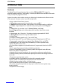
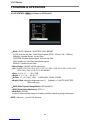
INTRODUCTION
Features
The Speed Dome Camera features a high resolution EX-View HAD CCD imager for
enhanced lowlight sensitivity. User friendly, on-screen pull-down menus and short-cuts make
it easy to setup and program functions.
System information aides trouble shooting by displaying the hardware and software version
of the camera’s firmware version, baud rate, and protocol.
! Built-in Optical Power Zoom Camera.
! 248 Presets programmed with view direction, zoom, and BLC.
! 8 Patterns record and play back user preference of surveillance path up to 480 sec.
! 16 Scans: 8 speed steps from 1 level to 8 levels panning with smooth Diagonal
Scan.
! 8 Tours: Each tour consists up to 63 (Preset, Pattern, and Scan).
Smooth Diagonal Scan mode and programmable Individual dwell time camera
functions.
! 8 Alarm inputs with 1~8 priority / 2 Auxiliary outputs programmable NC & NO.
! 8 Privacy Zones: Video off or up to 8 masked zones.
! 24 Area Titles.
! 64 steps of variable speed from 0.1˚/sec to 420˚/sec.
Max manual speed 420˚/sec with Turbo key pressed, Preset speed is 420˚/sec.
! Programmable user preferences of speed (Slow, Medium, Fast, and AUTO).
! Addressable up to 999 camera IDs (Extendable up to 3999 in special mode).
! Built-in RS-485 receiver driver.
! On-site software upgrade and upload/download of programmed data into the KBD/
Dome.
! Built-in power-line surge protection and lightning protection.
! Optional Tinted Bubble, Indoor & Outdoor pendant housing with heater & blower,
Indoor Flush Mount, Parapet mount.
! Adaptive tilt limit control according to the zoom ratio provides more useful picture.
! Sensitive panning control provides faster panning movement even though maximum
zoom ratio.
! Temperature sensing heater control.
! Automatic position compensation using the built in magnetic encoder.
! Built in system for undesired pan/tilt movement from external shock.
! Reliable motion tracking function to follow intruder.
! Block mode alarm preset provides a useful scanning method.
! On screen popup menu provides an easy way to control the dome system using
simple keyboard.
! Graphical on screen display.

VT-PTZ Series
10
INSTALLATION AND CONFIGURATION
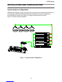
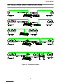
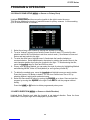
Typical system configuration
Additional Speed Dome joystick controllers and a variety of external switching devices such
as multiplexers (MUXes) and Digital Video Recorders (DVRs) may be incorporated to
accommodate the needs from a small to a large surveillance/security system.
Figure 1 illustrates sample installation.
Figure 1 - Typical System Configuration


VT-PTZ Series
12
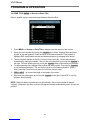
INSTALLATION AND CONFIGURATION
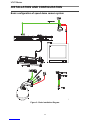
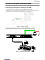
Connecting the Speed Dome directly into the DVR
• Locate the RS485 + & - conductor wire from the Speed Dome Camera.
· Connect the + & - into the Tx+ & Tx- ports of the DVR. Tx+ & Tx- ports can be found in
the rear part of the DVR. (22AWG shield twisted pair is recommended)
Figure 3 - Camera into DVR
Connecting the Speed Dome into the Controller via j-box
Figure 4 - Camera into Controller


VT-PTZ Series
14
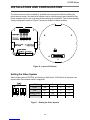
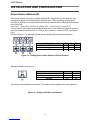
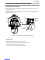
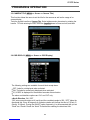
INSTALLATION AND CONFIGURATION
The dome camera must be installed by qualified service personnel. Before installing the
dome camera system, this instruction manual must be read thoroughly and understood fully.
Dome cameras must be set up properly before starting the installation. This involves properly
setting configuration switches. Figure 6 shows the location of these switches.
Figure 6 - Layout of Switches
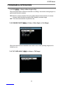
Setting the Video System
Select Video system NTSC/PAL and Analog or Web Dome, if Web Dome is selected, user
should check if purchased model is supported.
Figure 7 - Setting the Video System
SW2
1
2
3
4
NTSC
ON
X
X
X
PAL
OFF
X
X
X
Analog Dome
X
ON
X
X
Web Dome
X
OFF
X
X

VT-PTZ Series
15
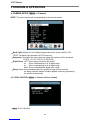
INSTALLATION AND CONFIGURATION
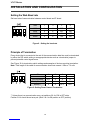
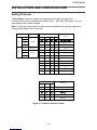
Setting the Web Baud rate
Set baud rate of communication between control board and IP board.
Figure 8 - Setting the baud rate
Principle of Termination
Every device that is connected at the end of the communication data line must be terminated
by either the DIP switch setting or an appropriate device such as a termination jumper to
prevent potential control signal errors.
See Figure 10 for termination switch settings and examples of devices requiring termination.
Note: Total length of the cable for communication should not exceed 1.2Km or .74 mile.
Figure 9- Setting Dome Camera Termination
** Unless there is a communication error, set switches 3 & 4 of S4 to OFF state.
Position 3 & 4 should be set as a pair. (Both 3 & 4 to ON position or OFF position)
SW2
1
2
3
4
4800
X
X
OFF
OFF
9600
X
X
OFF
ON
19200
X
X
ON
OFF
38400
X
X
ON
ON
S4
1
2
3
4
Terminated
ON
X
X
X
Not terminated
OFF
X
X
X
Pull Up/Down **
X
X
ON
ON
Normal **
X
X
OFF
OFF


VT-PTZ Series
17
INSTALLATION AND CONFIGURATION
Dome Camera Address (ID)
Each dome camera must have a unique address (ID). Identical IDs on the same line may
damage the control circuit caused by an electrical short. When installing multiple dome
cameras on a DVR, it is recommended that the dome camera ID’s be identical to the camera
port of the DVR.
Cam Port 1 = Dome ID1, Cam Port 2 = Dome ID 2 … Cam Port 16 = Dome ID 16.
If more than 16 dome cameras are installed using two or more DVRs the following formula is
useful to determine the Dome ID: ID =16x (n-1) +m (where n= number of DVR, m=Camera
Port)
Refer to Figures 11 for setting the dome camera address (ID) and protocol selection.
Figure 11 - Setting Dome Camera Address (ID) and Protocol
Setting installation environment
According to the installation environment, S7 needs to be set properly for heater operation.
Figure 12 - Setting installation environment
Dome ID
S3
S2
S1
001
0
0
1
.
.
.
.
999
9
9
9
S7
1
2
Indoor
off
off
Outdoor
on
off
Deicing
on
on

VT-PTZ Series
18
INSTALLATION AND CONFIGURATION
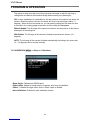
Setting Protocols
A Speed Dome camera is capable of negotiating with multiple protocols if the
communication speed is matched (same baud rate i.e., 9600 bps). See Figure 13 for the
appropriate protocol switch settings.
Note: Consult service personnel if a dome camera is installed with a device other than a
recommended Speed Dome Controller.
DIP S/W
FUNCTION
S5
Protocol
S5
D1
Protocol
D1
D2
D3
D4
D2
Off
Off
Off
Off
AUTO(No Parity)
D3
On
Off
Off
Off
AUTO(Even Parity)
D4
Off
On
Off
Off
PP
S6
D1
Extend ID
On
On
Off
Off
EZ
D2
Baud rate
Off
Off
On
Off
S2
D3
On
Off
On
Off
PD
D4
Off
On
On
Off
VC
On
On
On
Off
SN
Off
Off
Off
On
DC
Off
On
Off
On
PS
On
Off
On
On
VL
Off
On
On
On
DI
On
On
On
On
Factory Reset
S6
Baud rate
D2
D3
D4
Off
Off
Off
2400 bps
Off
Off
On
4800 bps
Off
On
Off
9600 bps
Off
On
On
19200 bps
On
Off
Off
38400 bps
Figure 13 - Protocol Selection Tables

VT-PTZ Series
19
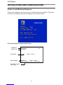
INSTALLATION AND CONFIGURATION
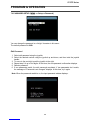
Connections
How to Connect RS485
The dome camera has a built-in RS-485 receiver so that it can be controlled remotely by
an external control device such as a joystick controller or a DVR.
RS-485: Connect the TXA (Tx+) and TXB (Tx-) of the RS485/422 control devices (KBD,
DVR…) to RXA (RX+), RXB (RX-) of the dome camera.
RS-485 does not allow for a star connection layout. A splitter is required if a star
connection layout is desired. RS-485 guarantees 1.2 Km of data line routing. A repeater
is recommended to extend over 1.2 Km. (22AWG shield twisted pair is recommended)
Connecting Video output
Figure 2 – Basic installation diagram
Connecting Alarms
! AL1 to 8 (Alarm In)
Magnetic, PIR or other external sensor devices can be used to signal the dome camera
reacting to an event.
See Chapter — Program and Operation for configuring alarm input.
! GND (Ground)
NOTE: All the connectors marked GND are common.
Connect the ground of the Alarm input and/or alarm output to the GND connector.
! NO / NC (Normally Opened or Normally Closed Dry Contact Relay Output)
The dome camera can activate external devices such as buzzers or lights using dry
contact relays. Connect the device to the NO (NC) (Alarm Out) and COM (Common)
connectors. See Chapter — Program and Operation for configuring alarm output.
Connecting the Power
Connect AC 24V 40VA power to the dome camera.
Use certified / Listed Class 2 power supply transformer only.
La pagina si sta caricando...
La pagina si sta caricando...
La pagina si sta caricando...
La pagina si sta caricando...
La pagina si sta caricando...
La pagina si sta caricando...
La pagina si sta caricando...
La pagina si sta caricando...
La pagina si sta caricando...
La pagina si sta caricando...
La pagina si sta caricando...
La pagina si sta caricando...
La pagina si sta caricando...
La pagina si sta caricando...
La pagina si sta caricando...
La pagina si sta caricando...
La pagina si sta caricando...
La pagina si sta caricando...
La pagina si sta caricando...
La pagina si sta caricando...
La pagina si sta caricando...
La pagina si sta caricando...
La pagina si sta caricando...
La pagina si sta caricando...
La pagina si sta caricando...
La pagina si sta caricando...
La pagina si sta caricando...
La pagina si sta caricando...
La pagina si sta caricando...
La pagina si sta caricando...
La pagina si sta caricando...
La pagina si sta caricando...
La pagina si sta caricando...
La pagina si sta caricando...
La pagina si sta caricando...
La pagina si sta caricando...
La pagina si sta caricando...
La pagina si sta caricando...
La pagina si sta caricando...
La pagina si sta caricando...
La pagina si sta caricando...
La pagina si sta caricando...
-
 1
1
-
 2
2
-
 3
3
-
 4
4
-
 5
5
-
 6
6
-
 7
7
-
 8
8
-
 9
9
-
 10
10
-
 11
11
-
 12
12
-
 13
13
-
 14
14
-
 15
15
-
 16
16
-
 17
17
-
 18
18
-
 19
19
-
 20
20
-
 21
21
-
 22
22
-
 23
23
-
 24
24
-
 25
25
-
 26
26
-
 27
27
-
 28
28
-
 29
29
-
 30
30
-
 31
31
-
 32
32
-
 33
33
-
 34
34
-
 35
35
-
 36
36
-
 37
37
-
 38
38
-
 39
39
-
 40
40
-
 41
41
-
 42
42
-
 43
43
-
 44
44
-
 45
45
-
 46
46
-
 47
47
-
 48
48
-
 49
49
-
 50
50
-
 51
51
-
 52
52
-
 53
53
-
 54
54
-
 55
55
-
 56
56
-
 57
57
-
 58
58
-
 59
59
-
 60
60
-
 61
61
-
 62
62


Vitek VT-PTZ40WH Manuale utente
- Categoria
- Telecamere di sicurezza
- Tipo
- Manuale utente
in altre lingue
- English: Vitek VT-PTZ40WH User manual
Documenti correlati
Altri documenti
-
Samsung SCC-C7478CP Manuale utente
-
Samsung SCC-C6323P Manuale utente
-
Elvox Telecamera speed dome IR Speed Dome Istruzioni per l'uso
-
-
-
-
-
-
-
AVer DL10 Guida utente