Cisco Systems 7936 Manuale utente
- Categoria
- Telefoni IP
- Tipo
- Manuale utente
Questo manuale è adatto anche per

Phone Guide
Cisco Unified IP Conference Station 7936
License and Warranty
1 Getting Started
2 Installation
3 Features and Functions
4 Cisco Unified IP Conference Station 7936 Web Interface
5 Using the Cisco Unified IP Conference Station 7936
6 General Troubleshooting Information
7 Obtaining Documentation
8 Documentation Feedback
9 Obtaining Technical Assistance
10 Obtaining Additional Publications and Information
11 Cisco One-Year Limited Hardware Warranty Terms

2
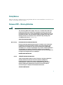
1 Getting Started
This guide helps you quickly set up and use the Cisco Unified IP Conference Station 7936
(Cisco model number CP-7936). The IP Conference Station requires Cisco Unified CallManager, and
your system administrator must prepare the network for the IP Conference Station. Verify with your
system administrator that the network is ready for the IP Conference Station. Be sure to read Release
Notes for Cisco Unified IP Conference Station 7936 and both the “Package Contents” section on
page 2 and the “Safety Notices” section on page 3 before you begin to set up and use the IP Conference
Station.
Note If your IP Conference Station is already set up, skip to the “Features and Functions” section
on page 17.
Introduction
The Cisco Unified IP Conference Station 7936 is an IP-based, hands-free conference room station that
uses Voice over IP (VoIP) technology. The IP Conference Station replaces a traditional analog
conferencing unit by providing business conferencing features—such as Call Hold, Call Resume, Call
Transfer, Call Release, Call Pickup, Group Pickup, Redial, Mute, and Conference—over an IP
network.
The Cisco Unified IP Conference Station 7936 features two outboard microphone jacks to enable the
use of optional, external microphones. Along with its enhanced speaker design, the IP Conference
Station is ideal for use in larger-sized conference rooms to facilitate conference calling. The
Cisco Unified IP Conference Station 7936 can also be ordered without external microphones for use
in smaller offices and conference rooms.
Package Contents
Review the following list to be sure that you have received all of the necessary items to install the
Cisco Unified IP Conference Station 7936.
• One Cisco Unified IP Conference Station 7936
• One 6-foot CAT 5 Cable
• One 25-foot CAT 5 Cable
• One Power Interface Module (PIM)
• One Power Supply Unit (a country-specific power cord must be ordered separately)
• Optional External Microphone Kit (with two external microphones), ordered separately
• One Regulatory Compliance and Safety Information Guide

3
Safety Notices
These are the safety considerations for using the IP Conference Station. Read these notices before you
install or use the IP Conference Station.
Statement 1071—Warning Definition
Warning
IMPORTANT SAFETY INSTRUCTIONS
This warning symbol means danger. You are in a situation that could cause
bodily injury. Before you work on any equipment, be aware of the hazards
involved with electrical circuitry and be familiar with standard practices for
preventing accidents. Use the statement number provided at the end of each
warning to locate its translation in the translated safety warnings that
accompanied this device.
Statement 1071
SAVE THESE INSTRUCTIONS
Waarschuwing
BELANGRIJKE VEILIGHEIDSINSTRUCTIES
Dit waarschuwingssymbool betekent gevaar. U verkeert in een situatie die
lichamelijk letsel kan veroorzaken. Voordat u aan enige apparatuur gaat
werken, dient u zich bewust te zijn van de bij elektrische schakelingen
betrokken risico's en dient u op de hoogte te zijn van de standaard praktijken
om ongelukken te voorkomen. Gebruik het nummer van de verklaring
onderaan de waarschuwing als u een vertaling van de waarschuwing die bij
het apparaat wordt geleverd, wilt raadplegen.
BEWAAR DEZE INSTRUCTIES
Varoitus
TÄRKEITÄ TURVALLISUUSOHJEITA
Tämä varoitusmerkki merkitsee vaaraa. Tilanne voi aiheuttaa ruumiillisia
vammoja. Ennen kuin käsittelet laitteistoa, huomioi sähköpiirien
käsittelemiseen liittyvät riskit ja tutustu onnettomuuksien yleisiin
ehkäisytapoihin. Turvallisuusvaroitusten käännökset löytyvät laitteen
mukana toimitettujen käännettyjen turvallisuusvaroitusten joukosta
varoitusten lopussa näkyvien lausuntonumeroiden avulla.
SÄILYTÄ NÄMÄ OHJEET

4
Attention
IMPORTANTES INFORMATIONS DE SÉCURITÉ
Ce symbole d'avertissement indique un danger. Vous vous trouvez dans une
situation pouvant entraîner des blessures ou des dommages corporels. Avant
de travailler sur un équipement, soyez conscient des dangers liés aux circuits
électriques et familiarisez-vous avec les procédures couramment utilisées
pour éviter les accidents. Pour prendre connaissance des traductions des
avertissements figurant dans les consignes de sécurité traduites qui
accompagnent cet appareil, référez-vous au numéro de l'instruction situé à la
fin de chaque avertissement.
CONSERVEZ CES INFORMATIONS
Warnung
WICHTIGE SICHERHEITSHINWEISE
Dieses Warnsymbol bedeutet Gefahr. Sie befinden sich in einer Situation, die
zu Verletzungen führen kann. Machen Sie sich vor der Arbeit mit Geräten mit
den Gefahren elektrischer Schaltungen und den üblichen Verfahren zur
Vorbeugung vor Unfällen vertraut. Suchen Sie mit der am Ende jeder Warnung
angegebenen Anweisungsnummer nach der jeweiligen Übersetzung in den
übersetzten Sicherheitshinweisen, die zusammen mit diesem Gerät
ausgeliefert wurden.
BEWAHREN SIE DIESE HINWEISE GUT AUF.
Avvertenza
IMPORTANTI ISTRUZIONI SULLA SICUREZZA
Questo simbolo di avvertenza indica un pericolo. La situazione potrebbe
causare infortuni alle persone. Prima di intervenire su qualsiasi
apparecchiatura, occorre essere al corrente dei pericoli relativi ai circuiti
elettrici e conoscere le procedure standard per la prevenzione di incidenti.
Utilizzare il numero di istruzione presente alla fine di ciascuna avvertenza per
individuare le traduzioni delle avvertenze riportate in questo documento.
CONSERVARE QUESTE ISTRUZIONI
Advarsel
VIKTIGE SIKKERHETSINSTRUKSJONER
Dette advarselssymbolet betyr fare. Du er i en situasjon som kan føre til skade
på person. Før du begynner å arbeide med noe av utstyret, må du være
oppmerksom på farene forbundet med elektriske kretser, og kjenne til
standardprosedyrer for å forhindre ulykker. Bruk nummeret i slutten av hver
advarsel for å finne oversettelsen i de oversatte sikkerhetsadvarslene som
fulgte med denne enheten.
TA VARE PÅ DISSE INSTRUKSJONENE

5
Aviso
INSTRUÇÕES IMPORTANTES DE SEGURANÇA
Este símbolo de aviso significa perigo. Você está em uma situação que poderá
ser causadora de lesões corporais. Antes de iniciar a utilização de qualquer
equipamento, tenha conhecimento dos perigos envolvidos no manuseio de
circuitos elétricos e familiarize-se com as práticas habituais de prevenção de
acidentes. Utilize o número da instrução fornecido ao final de cada aviso para
localizar sua tradução nos avisos de segurança traduzidos que acompanham
este dispositivo.
GUARDE ESTAS INSTRUÇÕES
¡Advertencia!
INSTRUCCIONES IMPORTANTES DE SEGURIDAD
Este símbolo de aviso indica peligro. Existe riesgo para su integridad física.
Antes de manipular cualquier equipo, considere los riesgos de la corriente
eléctrica y familiarícese con los procedimientos estándar de prevención de
accidentes. Al final de cada advertencia encontrará el número que le ayudará
a encontrar el texto traducido en el apartado de traducciones que acompaña
a este dispositivo.
GUARDE ESTAS INSTRUCCIONES
Varning!
VIKTIGA SÄKERHETSANVISNINGAR
Denna varningssignal signalerar fara. Du befinner dig i en situation som kan
leda till personskada. Innan du utför arbete på någon utrustning måste du vara
medveten om farorna med elkretsar och känna till vanliga förfaranden för att
förebygga olyckor. Använd det nummer som finns i slutet av varje varning för
att hitta dess översättning i de översatta säkerhetsvarningar som medföljer
denna anordning.
SPARA DESSA ANVISNINGAR

6

7
Statement 1007—TN and IT Power Systems
Warning
This equipment has been designed for connection to TN and IT power systems.
Statement
1007
Waarschuwing
Deze apparatuur is ontworpen voor verbindingen met TN en IT
energiesystemen.
Varoitus
Tämä laitteisto on suunniteltu yhdistettäväksi TN- ja
IT-sähkövoimajärjestelmiin.
Attention
Ce matériel a été conçu pour être connecté à des systèmes d'alimentation TN
et IT.
Warnung
Dieses Gerät ist so konstruiert, daß es an TN- und IT-Stromsysteme
angeschlossen werden kann.

8
Warning
Read the installation instructions before you connect the system to its power source.
Warning
Only trained and qualified personnel should be allowed to install, replace, or service this
equipment.
Avvertenza
Questa apparecchiatura è stata progettata per collegamenti a sistemi di
alimentazione TN e IT.
Advarsel
Dette utstyret er utformet for å kunne kobles til TN- og IT-strømsystemer.
Aviso
Este equipamento foi criado para ligações a sistemas de corrente TN e IT.
¡Advertencia!
Este equipo se ha diseñado para ser conectado a sistemas de alimentación
tipo TN o IT.
Varning!
Denna utrustning har konstruerats för anslutning till elkraftssystem av TN- och
IT-typ.

9
Warning
Ultimate disposal of this product should be handled according to all national laws and
regulations.
Warning
Do not work on the system or connect or disconnect cables during periods of lightning
activity.
Warning
To avoid electric shock, do not connect safety extra low voltage (SELV) circuits to
telephone network voltage (TNV) circuits. LAN ports contain SELV circuits, and WAN
ports contain TNV circuits. Some LAN and WAN ports both use RJ-45 connectors. Use
caution when connecting cables.
Warning
This product relies on the building's installation for short-circuit (overcurrent)
protection. Ensure that a fuse or circuit breaker no larger than 120 VAC, 15 A U.S.
(240 VAC, 10 A international) is used on the phase conductors (all current-carrying
conductors).
Warning
The plug-socket combination must be accessible at all times because it serves as the
main disconnecting device.
Caution The Cisco Unified IP Conference Station 7936 is inoperable during a power outage if it is
not supported by a UPS (uninterruptible power supply) when using a local power supply
unit. This affects your ability to reach 911.
Caution Using a cell, mobile, or GSM phone, or a two-way radio in close proximity to a
Cisco Unified IP Phone might cause interference. For more information, refer to the
manufacturer’s documentation of the interfering device.

10
Note To see additional safety warnings and translations of the safety warnings that appear in this
publication, refer to the Regulatory Compliance and Safety Information for the
Cisco Unified IP Phone 7900 Series that is shipped with your Cisco Unified
IP Conference Station 7936.
Using External Devices with Your Cisco Unified IP Phone
The following information applies when you use external devices with the Cisco Unified IP Phone:
• Depending on the quality of these devices and their proximity to other devices such as mobile
phones or two-way radios, some audio noise may still occur. In these cases, Cisco recommends
that you take one or more of the following actions:
–
Move the external device away from the source of the RF or AF signals.
–
Route the external device cables away from the source of the RF or AF signals.
–
Use screened cables for the external device, or use cables with a better screen and connector.
–
Shorten the length of the external device cable.
–
Apply ferrites or other such devices on the cables for the external device.
• Cisco cannot guarantee the performance of the system because Cisco has no control over the
quality of external devices, cables, and connectors. The system will perform adequately when
suitable devices are attached using good quality cables and connectors.
Caution In European Union countries, use only external speakers, microphones, and headsets that
are fully compliant with the EMC Directive [89/336/EC].
For more information on regulatory compliance and safety information, refer to the Regulatory
Compliance and Safety Information for the Cisco Unified IP Phone 7900 Series.
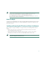
Accessibility Features
A list of accessibility features is available upon request.
2 Installation
This section provides basic installation instructions and information about obtaining optimal
performance with the Cisco Unified IP Conference Station 7936.

11
Note Be sure to review the “Package Contents” section on page 2 and the “Safety Notices” section
on page 3. Also read the Regulatory Compliance and Safety Information for the
Cisco Unified IP Phone 7900 Series, along with the Release Notes for
Cisco Unified IP Conference Station 7936. See the “Related Documentation” section on
page 17 for a list of relevant documentation.
Before You Begin
To ensure a successful installation, verify with your system administrator that the network is ready for
the IP Conference Station and that Cisco Unified CallManager is installed and configured for the
IP Conference Station.
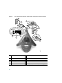
Installing and Connecting the IP Conference Station to the Network
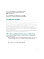
Refer to Figure 1 on page 12 and Figure 2 on page 13 when you are installing the IP Conference
Station.
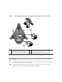
• Figure 1 shows the various components and power and cable connections used on the
Cisco Unified IP Conference Station 7936.
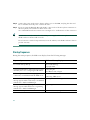
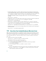
• Figure 2 shows the optional, external microphones and their connection to the external
microphone jacks on the bottom of the Cisco Unified IP Conference Station 7936.
Note Daisy-chaining Cisco Unified IP Conference Stations to other Cisco Unified IP Phones is not
a supported configuration and will not work.

12
Figure 1 Cisco Unified IP Conference Station 7936—Components and Connections
1
Power outlet in the wall
6
RJ-45 port on the bottom of the
IP Conference Station
2
Power supply power cord
7
Free end of the 25-foot CAT 5 cable
3
Power supply unit power cord
8
LAN connection on PIM
4
PIM
9
25-foot CAT 5 cable connection on PIM
5
LAN connection
10
DC adapter port on PIM for power supply unit
+
Foot
pad
+
99373
1
3
2
4
5
6
7
8
9
10

13
Figure 2 External Microphone Connections on the Cisco Unified IP Conference Station 7936
Perform these steps to install and connect the IP Conference Station to the network.
Step 1 Place the IP Conference Station on a flat surface, for example, a conference room table or
desktop.
Step 2 Connect one end of the 6-foot CAT 5 cable to your data network port and connect the other
end to the network (LAN) port on the PIM.
Step 3 Connect the free end of the 25-foot CAT 5 cable to the RJ-45 port on the bottom of the
IP Conference Station. (The cable is preplugged into the PIM.)
1
Connect one end of the external
microphone cable to the jack on the
underside of the external microphone.
2 Connect the other end of the external microphone
cable to the external microphone jack on the
underside of the IP Conference Station 7936.
105036
2
1
2
1

14
Step 4 Connect the power supply unit to the AC adapter port on the PIM, and plug the other end
into a standard electrical power outlet in the wall.
Step 5 If you are using the External Microphone Kit, connect each of the microphone extensions to
the microphone jacks installed on the bottom of the
Cisco Unified IP Conference Station 7936. See Figure 2 for an illustration of this connection.
Tip If you do not correctly connect the cables, PIM, power supply, and the microphone extensions,
the IP Conference Station will not work.
Use of non-Cisco-certified components may not work and may void the IP Conference Station
product warranty.
Startup Sequence
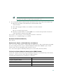
During the startup sequence, the LCD screen display shows the following messages.
Sequence Step LCD Screen Message Display
Startup—The startup process occurs about
15 seconds after power up.
Cisco Systems, Inc.
Polycom Technology
Copyright 2003
Configuring IP address—These messages appear
when the protocol is configuring the IP address.
Configuring IP
Press Menu to Reconfigure
TFTP configuration—This message appears when
connectivity is established with the TFTP server.
Station IP: IP address
Contacting: TFTP Server
Cisco Unified CallManager configuration—This
message appears when connectivity is established
with the Cisco Unified CallManager.
Opening: Cisco CallManager IP address
Cisco Unified CallManager registration—This
message appears while the device is registering
with the Cisco Unified CallManager.
Registering
Initialization complete. Press the Phone Key to get a dial tone

15
Note The startup process may take several minutes, and some of these messages may not appear
because of the access speed of your network.
After the IP Conference Station has successfully registered with the Cisco Unified CallManager, the
following information appears in the LCD screen display:
•
Date and time
• IP address
• Local phone number
• The message “Press the Phone Key to get a dial tone”
• Corp Dir and Ph Book softkeys
If the IP Conference Station successfully passes through these steps, it has started properly.
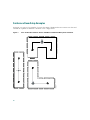
Guidelines for Best Performance
Follow these guidelines to ensure optimum performance with the IP Conference Station 7936 and the
external microphones. See the “Conference Room Setup Examples” section on page 16 for an
illustration of proper equipment placement for different conference room configurations.
• The recommended room conditions include closed offices and conference rooms up to
20 feet x 20 feet (without external microphones) and 20 feet x 30 feet (with external microphones)
without major glass and/or ceramic surface.
• Place the IP Conference Station 7936 base on a flat surface and make sure that it is clear from any
reflective surfaces.
• Maintain a minimum distance of 4 feet between each external microphone and the
IP Conference Station 7936 base and other objects.
• Make sure that all microphones are acoustically unobstructed.
• Position the external microphones toward the areas that need to be covered, and so that the main
pickup direction is pointed away from the IP Conference Station 7936 base.
• Seat all conference participants the same distance from the IP Conference Station 7936.
• Speak at normal conversation levels and direct your voice toward the IP Conference Station 7936.
• Do not move or handle the IP Conference Station
7936 base or the external microphones while on
a call.
• Minimize background noise from air conditioning units, fans, or other equipment in the office or
conference room.
• Do not shuffle papers near the IP Conference Station 7936.


17
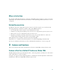
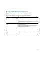
Where to Go for Help
If you require additional information or assistance with the IP Conference Station, contact your system
administrator. For technical assistance information, see the “Obtaining Technical Assistance” section
on page 42.
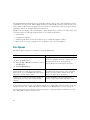
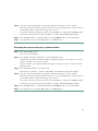
Related Documentation
In addition to this Cisco Unified IP Conference Station 7936 Phone Guide, you can reference the
following publications, which are available online at the URL listed below:
• Cisco Unified IP Conference Station 7936 Administration Guide
• Guidelines for Using External Microphones with the Cisco Unified IP Conference Station 7936
• Release Notes for Cisco Unified IP Conference Station 7936
• Regulatory Compliance and Safety Information for the Cisco Unified IP Phone 7900 Series
(included with your IP Conference Station, and available online)
These publications are available on the web at the following URL:
http://www.cisco.com/univercd/cc/td/doc/product/voice/c_ipphon/english/ipp7936/index.htm
For more documentation information, see the “Obtaining Documentation” section on page 40.
3 Features and Functions
This section describes the features and functions of the Cisco Unified IP Conference Station 7936.
Features of the Cisco Unified IP Conference Station 7936
The IP Conference Station provides business audio conferencing features and functions, as described
in the “Introduction” section on page 2.
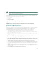
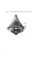
See Figure 4 on page 18 and its supporting table for an illustration and an explanation of the features
and functions of the Cisco Unified IP Conference Station 7936.

18
Figure 4 Cisco Unified IP Conference Station 7936—Features and Functions
99374
1
2
3
4
5
6
7
8
9
10
11
12

19
1
LEDs Provide call status indicators.
Call State Off—All LEDs off.
Powering On—Red LEDs on.
Ready—All LEDs off.
Dial Tone On—Green LEDs on.
Dialing—Green LEDs blinking.
Connected—Green LEDs on.
Mute—Red LEDs blinking.
Hold—Red LEDs on.
Incoming Call—Green LEDs blink with ring.
Ringing/Connecting—Green LEDs blinking.
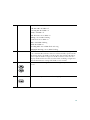
2
LCD screen Provides a status indicator that reads “Press the Phone Key to get a dial
tone” when the IP Conference Station is online and fully operational. In
the resting display, the LCD screen shows the date and time, IP address,
and local phone number assigned to the IP Conference Station. It also
displays the IP Conference Station system status, including configuration
and all administrative settings. The LCD screen is backlit.
3
Scroll buttons Allow you to scroll through the menus or through an open list in the LCD
screen.
4
Select button Selects a menu option or list item that is highlighted.

20
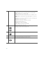
5
Softkeys Answer—Picks up the current call.
CFwdAll—Redirects all of your incoming calls to another number.
Confrn—Adds a party to a conference call.
Corp Dir—Lets you search a corporate directory for a number to call.
EndCall—Ends a call and returns to the resting display or to the active
call list.
GPickUp—Lets you pick up a call within your group or another group.
Hold—Puts the active call on hold.
PickUp—Lets you pick up a call within your group.
Ph Book—Opens the phone book.
NewCall—Lets you dial a new number.
Resume—Returns to the selected call on hold.
Transfer—Transfers the current call.
6
Volume buttons Increase or decrease the volume of the call, speaker, ringer, or dial tone,
depending on which sound is currently active.
7
Mute button Turns call muting on or off.
8
Keypad Allows you to dial phone numbers, add or edit phone book entries, and
enter other input depending on the menu selected.
9
Redial button Automatically redials the last dialed number.
La pagina si sta caricando...
La pagina si sta caricando...
La pagina si sta caricando...
La pagina si sta caricando...
La pagina si sta caricando...
La pagina si sta caricando...
La pagina si sta caricando...
La pagina si sta caricando...
La pagina si sta caricando...
La pagina si sta caricando...
La pagina si sta caricando...
La pagina si sta caricando...
La pagina si sta caricando...
La pagina si sta caricando...
La pagina si sta caricando...
La pagina si sta caricando...
La pagina si sta caricando...
La pagina si sta caricando...
La pagina si sta caricando...
La pagina si sta caricando...
La pagina si sta caricando...
La pagina si sta caricando...
La pagina si sta caricando...
La pagina si sta caricando...
La pagina si sta caricando...
La pagina si sta caricando...
La pagina si sta caricando...
La pagina si sta caricando...
-
 1
1
-
 2
2
-
 3
3
-
 4
4
-
 5
5
-
 6
6
-
 7
7
-
 8
8
-
 9
9
-
 10
10
-
 11
11
-
 12
12
-
 13
13
-
 14
14
-
 15
15
-
 16
16
-
 17
17
-
 18
18
-
 19
19
-
 20
20
-
 21
21
-
 22
22
-
 23
23
-
 24
24
-
 25
25
-
 26
26
-
 27
27
-
 28
28
-
 29
29
-
 30
30
-
 31
31
-
 32
32
-
 33
33
-
 34
34
-
 35
35
-
 36
36
-
 37
37
-
 38
38
-
 39
39
-
 40
40
-
 41
41
-
 42
42
-
 43
43
-
 44
44
-
 45
45
-
 46
46
-
 47
47
-
 48
48


Cisco Systems 7936 Manuale utente
- Categoria
- Telefoni IP
- Tipo
- Manuale utente
- Questo manuale è adatto anche per
in altre lingue
- English: Cisco Systems 7936 User manual
Documenti correlati
Altri documenti
-
Cisco AIR-WLC4404-100-K9 specificazione
-
Cisco 7940 Series Manuale utente
-
-
Yamaha CS-700 Guida utente
-
-
Mitel OfficeSuite 5330 Manuale utente
-
-
-
NEC DT710 Manuale utente
-
LG-Ericsson GDC-400H Manuale utente