IMG STAGELINE 25.3490 Manuale utente
- Categoria
- Microfoni
- Tipo
- Manuale utente

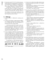
ELECTRONICS FOR SPECIALISTS ELECTRONICS FOR SPECIALISTS ELECTRONICS FOR SPECIALISTS ELECTRONICS FOR SPECIALISTS
TXS-611SET Bestell-Nr. • Order No. 25.3650 863 – 865 MHz
TXS-616SET Bestell-Nr. • Order No. 25.3490 672 – 697 MHz
TXS-631SET Bestell-Nr. • Order No. 25.3660 863 – 865 MHz
TXS-636SET Bestell-Nr. • Order No. 25.3500 672 – 697 MHz
BEDIENUNGSANLEITUNG
INSTRUCTION MANUAL
MODE D’EMPLOI
ISTRUZIONI PER L’USO
GEBRUIKSAANWIJZING
MANUAL DE INSTRUCCIONES
INSTRUKCJA OBSŁUGI
Drahtloses Mikrofonsystem
Wireless Microphone System


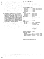
3
ON
LR6.AALR6.AA
CHANNEL
BATT
HI ON
LO OFF
POWER
LOCK
IR
CHANNEL
BATT
0 10
MIN MAX
MIC OUT (BAL.)
SQUELCHVOLUME
POWER
LINE OUT (UNBAL.)
DC INPUT
ACT
TXS-6..SET
IRCHANNELSELECTA B
AF RF
A
B
1 12 3 4 5 6 7
8 9 10 11 12 13
14
15
16
17
21
22
23
24
25
26
28
20
18
19
➀
➂➁

4
English
English Page
Contents
Français
Français Page
Table des matières
Italiano
Italiano Pagina
Indice
Español
Español Página
Contenidos
Nederlands
Nederlands Pagina
Inhoud
Polski
Polski Strona
Spis treści
Deutsch
Deutsch Seite
Inhalt
Deutsch
Inhalt
1 Einsatzmöglichkeiten . . . . . . . . . . 4
2 Übersicht . . . . . . . . . . . . . . . . 4
2.1 Multifrequenz-Empfänger . . . . . . . . . 4
2.2 Funkmikrofon . . . . . . . . . . . . . . .4
2.3 Taschensender. . . . . . . . . . . . . . .5
3 Hinweise für den sicherenGebrauch . . 5
3.1 Konformität und Zulassung . . . . . . . . 5
4 Inbetriebnahme . . . . . . . . . . . . . 6
4.1 Empfänger anschließen . . . . . . . . . . 6
4.2 Batterien in den Sender einsetzen . . . . . 6
4.2.1 Funkmikrofon
1
. . . . . . . . . . . . . .6
4.2.2 Taschensender
2
. . . . . . . . . . . . . 6
4.3 Krawattenmikrofon
2
und Taschensender
2
anschließen und befestigen
. . . . . . . . 6
4.4 Übertragungskanal einstellen . . . . . . . 6
5 Bedienung . . . . . . . . . . . . . . . .7
6 Technische Daten . . . . . . . . . . . . 8
Drahtloses Mikrofonsystem
Diese Bedienungsanleitung richtet sich an Benutzer
ohne besondere Fachkenntnisse. Bitte lesen Sie die
Anleitung vor dem Betrieb gründlich durch und
heben Sie sie für ein späteres Nachlesen auf.
Auf der ausklappbaren Seite 3 finden Sie alle
beschriebenen Bedienelemente und Anschlüsse.
1 Einsatzmöglichkeiten
Mit diesem Mulitfrequenz-Mikrofonsystem, das
im UHF-Bereich arbeitet, lassen sich Sprache und
Gesang drahtlos zu einer Verstärkeranlage über-
tragen. Es eignet sich damit optimal für Anwen-
dungen, die uneingeschränkte Bewegungsfreiheit
erfordern, z. B. bei Bühnenshows, für den DJ-Ein-
satz, bei Sportveranstaltungen.
Besonders komfortabel ist das System durch
die ACT-Funktion (Automatic Channel Targeting).
Damit wird per Knopfdruck über ein Infrarotsignal
das Funkmikrofon oder der Taschensender auf den
am Empfänger gewählten Kanal eingestellt.
Das Mikrofonsystem besteht aus:
1 Multifrequenz-Empfänger in True-Diversity-
Technik*
1 Steckernetzgerät für den Empfänger
1 Audiokabel (2 × 6,3-mm-Klinke)
1 Funkmikrofon (bei TXS-611SET / TXS-616SET) oder
1 Taschensender mit Krawattenmikrofon
(bei TXS-631SET / TXS-636SET)
* True-Diversity-Technik:
Das vom Funkmikrofon oder Taschensender ausgestrahlte
Signal wird von zwei Antennen empfangen und in zwei
separaten Empfangsteilen verstärkt. Das jeweils besser
empfangene Signal wird dann weiterverarbeitet.
2 Übersicht
2.1 Multifrequenz-Empfänger
1 Empfangsantennen A und B
2 Taste SELECT zur Kanaleinstellung
– Zum automatischen Suchen eines freien Emp-
fangskanals die Taste kurz drücken.
– Zur manuellen Einstellung die Taste SELECT so
lange drücken, bis die Einerstelle im Display
(3) blinkt. Durch kurzes Drücken der Taste
die Einerstelle einstellen. Die Taste erneut ge-
drückt halten, bis die Zehnerstelle im Display
blinkt. Durch kurzes Drücken die Zehnerstelle
einstellen. (Die den Kanälen entsprechenden
Frequenzen sind in den Tabellen auf der
Seite 40 angegeben.)
3 Display zur Kanalanzeige
4 Anzeige AF (audio frequency): leuchtet, wenn
das empfangene Tonsignal einen bestimmten
Pegel überschreitet
5
Empfangsanzeigen RF (radio frequency) A
und B: signalisieren, welches der beiden Emp-
fangsteile des Gerätes das stärkere Funksignal
empfängt
6 IR-Fenster für die Infrarotsignale zur Kanalein-
stellung des Funkmikrofons oder des Taschen-
senders
7 Taste ACT zum Aussenden der Infrarotsignale
für die Kanaleinstellung des Funkmikrofons oder
des Taschensenders
8
Stromversorgungsbuchse zum Anschluss des
beiliegenden Netzgerätes
9 Ein- und Auschalter POWER
10
XLR-Audioausgang zum Anschluss an einen
Mikrofoneingang
11
Audioausgang (6,3-mm-Klinke) zum Anschluss
an einen Line-Eingang
12 Lautstärkeregler VOLUME für das Audiosignal
der Ausgänge (10, 11)
13 Regler SQUELCH zum Einstellen der Ansprech-
schwelle für die Störunterdrückung
2.2 Funkmikrofon
nur bei TXS-611SET und TXS-616SET
14 Display mit Kanal- und Batterieanzeige
15 Sensor für die Infrarotsignale zur Kanaleinstel-
lung
16 Ein- und Ausschalter
untere Position: Aus
mittlere Position: Mute
obere Position: Ein

5
Deutsch
17 Batteriefach
18 Schalter LOCK für die Bediensperre
Position OFF Sperre ausgeschaltet
Position ON Sperre eingeschaltet
19 Schalter POWER für die Sendeleistung
Position LO geringe Sendeleistung
Position HI hohe Sendeleistung
2.3 Taschensender
nur bei TXS-631SET und TXS-636SET
20 Sendeantenne
21 Ein- und Ausschalter
OFF = Aus
STBY = Mute
ON = Ein
22 Display mit Kanal- und Batterieanzeige
23 Sensor für die Infrarotsignale zur Kanaleinstel-
lung
24 Batteriefachdeckel
25 Anschlussbuchse für das Krawattenmikrofon
26 Gürtelklemme
27
Regler GAIN zum Einstellen der Verstärkung des
Mikrofonsignals
28 Batteriefach
3 Hinweise für den
sicherenGebrauch
Die Geräte (Empfänger, Netzgerät, Funkmikrofon
oder Taschensender) entsprechen allen relevan
-
ten Richtlinien der EU und tragen deshalb das
-Zeichen.
WARNUNG
Das Netzgerät wird mit lebensge-
fährlicher Netzspannung versorgt.
Nehmen Sie deshalb niemals selbst
Eingriffe daran vor. Es besteht die
Gefahr eines elektrischen Schlages.
•
Das Funksystem ist nur für die Verwendung im
Innenbereich geeignet. Schützen Sie die Geräte
vor Tropf- und Spritzwasser, hoher Luftfeuchtig-
keit und Hitze (zulässiger Einsatztemperaturbe-
reich 0 – 40 °C).
•
Nehmen Sie den Empfänger nicht in Betrieb und
ziehen Sie sofort das Netzgerät aus der Steck-
dose,
1. wenn sichtbare Schäden am Empfänger oder
am Netzgerät vorhanden sind,
2. wenn nach einem Sturz oder Ähnlichem der
Verdacht auf einen Defekt besteht,
3. wenn Funktionsstörungen auftreten.
Lassen Sie die Geräte in jedem Fall in einer Fach-
werkstatt reparieren.
•
Verwenden Sie zum Reinigen nur ein trockenes,
weiches Tuch, niemals Wasser oder Chemikalien.
•
Werden die Geräte zweckentfremdet, nicht
richtig angeschlossen, falsch bedient oder nicht
fachgerecht repariert, kann keine Haftung für
daraus resultierende Sach- oder Personenschä-
den und keine Garantie für die Geräte über-
nommen werden.
Sollen die Geräte endgültig aus dem
Betrieb genommen werden, übergeben
Sie sie zur umweltgerechten Entsorgung
einem örtlichen Recyclingbetrieb.
3.1 Konformität und Zulassung
Hiermit erklärt MONACOR INTERNATIONAL, dass
sich die drahtlosen Mikrofonsysteme
TXS-611SET
TXS-616SET
TXS-631SET
TXS-636SET
in Übereinstimmung mit den grundlegenden An-
forderungen und den übrigen einschlägigen Be-
stimmungen der Richtlinie 2014 / 53 / EU befinden.
Die EU-Konformitätserklärungen sind im Internet
verfügbar:
www.imgstageline.de
Die Modelle TXS-611SET und TXS-631SET sind für
den Betrieb in den EU-Staaten allgemein zugelas-
sen und anmelde- und gebührenfrei.
Für die Modelle TXS-616SET und TXS-636SET
bestehen Beschränkungen oder Anforderun-
gen in folgenden Ländern:
CZ DE EL FI FR
IT LT MT PL
Diese müssen im Gebiet der Bundesrepublik
Deutschland eine Frequenzzuteilung (kosten-
pflichtig) erhalten. Die Formulare und Hinweise
zur Anmeldung der Sender finden Sie im Internet
auf der Seite der Bundesnetzagentur
www.bundesnetzagentur.de
In anderen Ländern muss eine entsprechende Ge-
nehmigung beantragt werden. Informieren Sie sich
bitte vor der Inbetriebnahme des Mikrofonsystems
außerhalb Deutschlands bei der MONACOR-Nie-
derlassung oder der entsprechenden Behörde des

6
Deutsch
Landes. Links zu den nationalen Behörden finden
Sie über die folgende Internetadresse:
www.cept.org
t ECC
t Topics
t Short Range Devices (SRD) and other R&T TE
sub-classes
t EFIS and National Frequency Tables
4 Inbetriebnahme
4.1 Empfänger anschließen
1)
Den Empfänger an das nachfolgende Gerät
(z. B. Verstärker, Mischpult) anschließen. Dazu
sind zwei Audioausgänge vorhanden:
– MIC OUT (10) als XLR-Buchse, symmetrisch,
zum Anschluss an einen Mikrofoneingang
– LINE OUT (11) als 6,3-mm-Klinkenbuchse,
asymmetrisch, zum Anschluss an einen Ein-
gang mit Line-Pegel; hierfür kann das bei-
liegende Anschlusskabel verwendet werden
2) Das beiliegende Netzgerät an die Stromversor-
gungsbuchse (8) anschließen und in eine Steck-
dose (230 V/ 50 Hz) stecken.
4.2 Batterien in den Sender einsetzen
Für den Betrieb des Funkmikrofons und des
Taschensenders werden zwei 1,5-V-Batterien der
Größe Mignon (AA) benötigt.
•
Setzen Sie nur Batterien oder Akkus des gleichen
Typs ein und tauschen Sie sie immer komplett aus.
•
Nehmen Sie bei längeren Nichtgebrauch die Bat-
terien heraus. So bleibt das Gerät bei einem even-
tuellen Auslaufen der Batterien unbe schädigt.
Verbrauchte Batterien und defekte Akkus
dürfen nicht in den Hausmüll geworfen
werden. Geben Sie sie zur umweltgerech-
ten Entsorgung nur in den Sondermüll
(z. B. Sammelbehälter im Einzelhandel).
4.2.1 Funkmikrofon
1
Zum Öffnen des Batteriefachs (17) auf den Pfeil des
Batteriefachdeckels drücken und dabei den Deckel
nach unten schieben.
Die Batterien mit den Plus- und Minuspolen,
wie im Batteriefach angegeben, einsetzen und den
Batteriefachdeckel wieder aufsetzen.
4.2.2 Taschensender
2
Zum Öffnen des Batteriefachs (28) auf den Pfeil
des Batteriefachdeckels (24) drücken und dabei
den Deckel nach unten schieben.
Die Batterien mit den Plus- und Minuspolen,
wie in der Abb. 3 dargestellt, einsetzen und den
Batteriefachdeckel wieder aufsetzen.
4.3 Krawattenmikrofon
2
und Taschen-
sender
2
anschließen und befestigen
1)
Den Stecker des Krawattenmikrofons in die
Klinkenbuchse (25) des Senders stecken. Um
den Stecker vor einem Herausziehen zu sichern,
die Überwurfmutter des Steckers auf die Buchse
schrauben.
2)
Das Krawattenmikrofon an der Kleidung befes-
tigen, möglichst nahe am Mund.
3)
Nach dem Durchführen aller Einstellungen
(Kap.4.4 und 5) den Sender mit der Klemme
(26) an der Kleidung befestigen (z. B. am Gürtel
oder am Hosenbund).
4.4 Übertragungskanal einstellen
Ein freier Übertragungskanal kann am Empfän-
ger automatisch gesucht oder manuell eingestellt
werden. Anschließend wird komfortabel nur durch
einen Knopfdruck das Funkmikrofon
1
bzw. der
Taschensender
2
mit Hilfe eines Infrarotsignals auf
den gleichen Kanal eingestellt.
1)
Den Empfänger mit dem Schalter POWER (9)
einschalten. Zum Einschalten des Taschensen-
ders den Schalter (21) in die Position ON schie-
ben. Zum Einschalten des Funkmikrofons den
Schalter (16) in die obere Position schieben.
Nach den Einschalten leuchtet das entspre-
chende Display (3, 14, 22).
2) Zum automatischen Suchen eines freien Ka-
nals die Taste SELECT (2) kurz drücken. Das
Display (3) signalisiert den Suchvorgang durch
ein umlaufendes Anzeigesegment:
Nach kurzer Zeit zeigt das Display die Nummer
des gefundenen Kanals an. Die zugehörigen
Frequenzen sind in den Tabellen auf der Seite
40 angegeben.
3) Zum manuellen Einstellen einer bestimmten
Übertragungsfrequenz die zugehörige Kanal-
nummer aus den Tabellen auf der Seite 40
heraussuchen. Zum Einstellen der Kanalnummer
1
nur bei TXS-611SET und TXS-616SET
2
nur bei TXS-631SET und TXS-636SET

7
Deutsch
die Taste SELECT (2) so lange drücken, bis die
Einerstelle im Display (3) blinkt. Durch kurzes
Drücken der Taste SELECT die Einerstelle ein-
stellen. Die Taste erneut gedrückt halten, bis
die Zehnerstelle im Display blinkt. Durch kur-
zes Drücken die Zehnerstelle einstellen. Einige
Sekunden nach dem letzten Tastendruck wird
das Blinken beendet. Die Kanaleinstellung ist
dann gespeichert.
4)
Den Infrarotsensor (15, 23) des Funkmikrofons /
Taschensenders in Richtung des IR-Fensters(6)
am Empfänger halten. Der Abstand darf nicht
mehr als 1,5 m betragen und es muss Sicht-
verbindung zwischen Sensor und IR-Fenster
bestehen.
Die Taste ACT (7) einige Sekunden drü-
cken, bis die Display-Hintergrundbeleuchtung
des Funkmikrofons bzw. des Taschensenders
aufleuchtet. Das Funkmikrofon bzw. der Ta-
schensender ist damit auf den gleichen Kanal
wie der Empfänger eingestellt. Das Display (14
bzw. 22) zeigt die Kanalnummer an.
5 Bedienung
1) Die Empfangsantennen (1) senkrecht stellen.
2)
Zuerst den Empfänger mit dem Schalter POWER
(9) einschalten. Die Anzeige AF (4) blinkt zwei-
mal auf. Das Display (3) zeigt den eingestellten
Übertragungskanal an.
Leuchtet bei noch ausgeschaltetem Funk-
mikrofon
1
bzw. Taschensender
2
eine der Emp-
fangsanzeigen RF (5), werden Störungen oder
Signale eines anderen Funksystems empfangen.
In diesem Fall einen anderen Kanal einstellen
(
☞
Kap. 4.4).
3)
Zum Einschalten des Taschensenders den Schal-
ter (21) in die Position ON schieben. Zum Ein-
schalten des Funkmikrofons den Schalter (16) in
die obere Position schieben. Für eine Tonüber-
tragung den Schalter am Funkmikrofon ganz
nach oben schieben bzw. am Taschensender
ganz in die Position ON. In der Mittelposition
arbeitet zwar der Sender, jedoch ist das Mikro-
fonsignal stumm geschaltet.
Nach den Einschalten leuchtet für einige
Sekunden die Hintergrundbeleuchtung des Dis-
plays (14, 22). Das Display zeigt den eingestell-
ten Kanal und den Ladezustand der Batterien an:
BATT BATT BATT
voll entladen
4)
Am Funkmikrofon mit dem Schalter POWER (19)
im Batteriefach die Sendeleistung einstellen:
– obere Position HI = hohe Leistung für eine
große Reichweite, jedoch kürzere Betriebs-
dauer der Batterie
– untere Position LO = geringe Leistung für
eine längere Betriebsdauer, jedoch kürzere
Reichweite
5)
Bei eingeschaltetem Sender (Funkmikrofon bzw.
Taschensender) leuchtet am Empfänger eine
der Empfangsanzeigen RF A oder B (5) entspre-
chend, welches Empfangsteil das bessere Signal
liefert. Leuchtet keine Anzeige, überprüfen:
a
Ist der Sender auf den gleichen Kanal wie der
Empfänger eingestellt?
Werden am Empfänger und am Funkmik-
rofon / Taschensender verschiedene Kanäle
angezeigt, den Bedienschritt 4 des Kapitels
4.4 ausführen.
b Sind die Batterien des Senders verbraucht?
c Ist das Funkmikrofon auf eine niedrige Sen-
deleistung eingestellt?
d Ist der Abstand zwischen Sender und Emp-
fänger zu groß?
Reichweite
TXS-611 / -631 / -636SET : ca. 30 m
TXS-616SET: ca. 50 m
e Ist der Empfang durch Metallgegenstände in
der Übertragungsstrecke gestört?
f
Lässt sich der Empfang durch Schwenken der
Empfangsantennen (1) verbessern?
g
Ist die Störunterdrückung mit dem Regler
SQUELCH (13) zu hoch eingestellt?
(
☞
Bedienschritt 7)
6)
Das nachfolgende Audiogerät einschalten bzw.
den zugehörigen Mischpultregler aufziehen.
In das Mikrofon sprechen / singen und mit dem
Lautstärkeregler VOLUME (12) den Ausgangs-
pegel des Empfängers an den Eingang des
nachfolgenden Gerätes anpassen.
Bei dem Taschensender lässt sich für das
angeschlossene Mikrofon die Verstärkung mit
dem Regler GAIN (27) auf der Rückseite einstel-
len: Ist das Mikrofonsignal zu laut und verzerrt,
den Regler mit einem kleinen Schraubendreher
zurückdrehen. Bei einem zu leisen Signal ergibt
sich dagegen ein schlechter Rauschabstand; den
Regler dann entsprechend aufdrehen.
7)
Mit dem Regler SQUELCH (13) den Schwellwert
einstellen, bei dem die Störunterdrückung an-
sprechen soll. Die Störunterdrückung schaltet
den Empfänger stumm, wenn in Sprech- oder
Hinweis: Blinkt die Anzeige BATT, die Batterien aus-
tauschen.

8
Deutsch
Gesangspausen Störsignale empfangen wer-
den, deren Pegel unter dem eingestellten
Schwellwert liegen. Ein hoher Schwellwert
reduziert jedoch auch die Reichweite des Mikro-
fonsystems. Sinkt nämlich die Funksignalstärke
unter den eingestellten Schwellwert, wird der
Empfänger ebenfalls stumm geschaltet. Darum
bei gutem Empfang einen höheren Schwellwert
einstellen (Regler in Richtung MAX drehen) und
bei größerer Entfernung zwischen Sender und
Empfänger einen niedrigeren Wert (Regler in
Richtung MIN drehen).
8)
Bei dem Funkmikrofon lässt sich die Bedie-
nung sperren. Wird der Schalter LOCK (18) im
Batteriefach in die Position ON geschoben, ist
die Sperre eingeschaltet. Im Display erscheint
ein Schlüsselsymbol. Das Mikrofon kann dann
nicht mit dem Schalter (16) ausgeschaltet oder
per Infrarotsignal auf einen anderen Kanal ein-
gestellt werden. Das Mikrofonsignal lässt sich
jedoch weiterhin stumm schalten, wenn der
Schalter (16) in die mittlere oder untere Position
geschoben wird.
9) Nach dem Betrieb die Geräte mit dem entspre-
chenden Schalter (9, 16, 21) ausschalten. Wird
das Mikrofonsystem längere Zeit nicht benutzt,
das Netzgerät des Empfängers aus der Steck-
dose ziehen, denn es verbraucht auch bei aus-
geschaltetem Empfänger einen geringen Strom.
6 Technische Daten
Trägerfrequenzen
TXS-611 / -631SET:. . . .863 – 865 MHz
TXS-616 / -636SET:. . . .672 – 697 MHz
Kanäle siehe Seite 40
Sendeleistung (EIRP)
TXS-611SET: . . . . . . . .< 10 mW (HI), 1,0 mW (LO)
TXS-616SET: . . . . . . . .< 25 mW (HI), 2,5 mW (LO)
TXS-631SET: . . . . . . . .< 10 mW
TXS-636SET: . . . . . . . .< 10 mW
Reichweite
TXS-611 / -631SET:. . . .ca. 30 m
TXS-616SET: . . . . . . . .ca. 50 m
TXS-636SET: . . . . . . . .ca. 30 m
HF-Rauschabstand: . . . .105 dB
Audiofrequenzbereich: .50 – 18 000 Hz, ±3 dB
Dynamik: . . . . . . . . . . .120 dB
Klirrfaktor: . . . . . . . . . .< 0,5 %
Audioausgänge
MIC OUT: . . . . . . . . . .25 mV, 10 kΩ, XLR, sym.
LINE OUT: . . . . . . . . . .350 mV, 10 kΩ,
6,3-mm-Klinke, asym.
Stromversorgung
Empfänger: . . . . . . . .über beiliegendes Netzgerät
an 230 V/ 50 Hz
Funkmikrofon /
Taschensender: . . . . . .2 × 1,5-V-Batterie,
Größe Mignon (AA)
Einsatztemperatur:
. . . .0 – 40 °C
Abmessungen, Gewicht
Empfänger: . . . . . . . .152 × 38 × 120 mm, 482 g
Funkmikrofon: . . . . . .⌀ 52 mm × 275 mm, 235 g
Taschensender: . . . . . .62 × 105 × 25 mm, 88 g
Änderungen vorbehalten.
Diese Bedienungsanleitung ist urheberrechtlich für MONACOR
®
INTERNATIONAL GmbH & Co. KG geschützt.
Eine Reproduktion für eigene kommerzielle Zwecke – auch auszugsweise – ist untersagt.

9

10
Deutsch
Deutsch Seite
Inhalt
Français
Français Page
Table des matières
Italiano
Italiano Pagina
Indice
Español
Español Página
Contenidos
Nederlands
Nederlands Pagina
Inhoud
Polski
Polski Strona
Spis treści
English
English Page
Contents
English
Contents
1 Applications . . . . . . . . . . . . . . 10
2 Operating Elements and Connections . 10
2.1 Multi-frequency receiver . . . . . . . . . 10
2.2 Wireless microphone . . . . . . . . . . 10
2.3 Pocket transmitter . . . . . . . . . . . . 11
3 Safety Notes . . . . . . . . . . . . . . 11
3.1 Conformity and approval . . . . . . . . 11
4 Setting into Operation . . . . . . . . 12
4.1 Connecting the receiver . . . . . . . . . 12
4.2 Inserting the batteries into the transmitter 12
4.2.1 Wireless microphone
1
. . . . . . . . . 12
4.2.2 Pocket transmitter
2
. . . . . . . . . . . 12
4.3 Connecting and attaching
the tie clip microphone
2
and the pocket transmitter
2
. . . . . . . 12
4.4 Adjusting the transmission channel. . . . 12
5 Operation . . . . . . . . . . . . . . . 13
6 Specifications . . . . . . . . . . . . . 14
Wireless Microphone System
These instructions are intended for users without
any specific technical knowledge. Please read these
instructions carefully prior to operating the unit and
keep them for later reference.
All operating elements and connections de-
scribed can be found on the fold-out page 3.
1 Applications
This multi-frequency microphone system operating
in the UHF range is capable of wireless transmission
of speech and vocals to an amplifier system. Thus,
it is ideally suited for applications requiring total
freedom of movement, e. g. for stage shows, DJ
applications, sports events.
The ACT function (automatic channel target-
ing) is a most convenient feature of the system:
Simply press a button to adjust the wireless mi-
crophone or the pocket transmitter to the channel
selected on the receiver via IR signal.
The microphone system includes:
1 multi-frequency receiver in True Diversity tech-
nology*
1 plug-in power supply unit for the receiver
1 audio cable (2 × 6.3 mm plug)
1 wireless microphone (for TXS-611SET / TXS-616SET) or
1 pocket transmitter with tie clip microphone
(for TXS-631SET / TXS-636SET)
* True Diversity technology
The signal coming from the wireless microphone or
the pocket transmitter is received by two antennas and
amplified in two separate receiving parts. The signal offer-
ing the best reception quality is then processed.
2 Operating Elements and
Connections
2.1 Multi-frequency receiver
1 Receiving antennas A and B
2 Button SELECT for channel adjustment
– To automatically scan a free reception channel,
press the button briefly.
– To manually adjust a channel, keep the button
SELECT pressed until the units digit on the
display (3) starts flashing. Press the button
briefly to adjust the units digit. Keep the but-
ton pressed again until the tens digit on the
display starts flashing. Press the button briefly
to adjust the tens digit. (The frequencies cor-
responding to the channels can be found in
the tables on page40.)
3 Display for channel indication
4
LED AF (audio frequency): lighting up when the
received audio signal exceeds a defined level
5 Reception LEDs RF (radio frequency) A and B:
to indicate which of the two receiving parts of
the unit receives the more powerful radio signal
6 IR window for the IR signals to adjust the chan-
nel of the wireless microphone or of the pocket
transmitter
7 Button ACT for sending the IR signals to adjust
the channel of the wireless microphone or of
the pocket transmitter
8
Power supply jack to connect the power supply
unit provided
9 POWER switch
10
XLR audio output for connection to a micro-
phone input
11 Audio output (6.3 mm jack) for connection to
a line input
12
VOLUME control for the audio signal of the
outputs (10, 11)
13
SQUELCH control to adjust the threshold for
interference suppression
2.2 Wireless microphone
for TXS-611SET and TXS-616SET only
14
Display with channel indication and battery
status indication
15 Sensor for the IR signals to adjust the channel
16 On / off switch
lower position: off
mid-position: mute
upper position: on

11
English
17 Battery compartment
18 Switch LOCK to lock the microphone
position OFF lock deactivated
position ON lock activated
19 Switch POWER for the transmission power
position LO low transmission power
position HI high transmission power
2.3 Pocket transmitter
for TXS-631SET and TXS-636SET only
20 Transmitting antenna
21 On / off switch
OFF
STBY = mute
ON
22
Display with channel indication and battery
status indication
23 Sensor for the IR signals to adjust the channel
24 Cover of battery compartment
25 Jack to connect the tie clip microphone
26 Belt clip
27 GAIN control to adjust the gain of the micro-
phone signal
28 Battery compartment
3 Safety Notes
The units (receiver, power supply unit, wireless
microphone or pocket transmitter) correspond to
all relevant directives of the EU and are therefore
marked with .
WARNING The power supply unit uses danger-
ous mains voltage. Leave servicing
to skilled personnel only. Inexpert
handling of the unit may result in
electric shock.
•
The wireless system is suitable for indoor use
only. Protect the units against dripping water
and splash water, high air humidity and heat (ad-
missible ambient temperature range 0 – 40 °C).
•
Do not operate the receiver and immediately dis-
connect the power supply unit from the socket
1. if the receiver or the power supply unit is vis-
ibly damaged,
2. if a defect might have occurred after a unit
was dropped or suffered a similar accident,
3. if malfunctions occur.
In any case the units must be repaired by skilled
personnel.
•
For cleaning only use a dry, soft cloth; never use
water or chemicals.
•
No guarantee claims for the units and no liability
for any resulting personal damage or material
damage will be accepted if the units are used for
other purposes than originally intended, if they
are not correctly connected or operated, or if
they are not repaired in an expert way.
If the units are to be put out of operation
definitively, take them to a local recycling
plant for a disposal which is not harmful
to the environment.
3.1 Conformity and approval
Herewith, MONACOR INTERNATIONAL declare that
the wireless microphone systems
TXS-611SET
TXS-616SET
TXS-631SET
TXS-636SET
are in accordance with the basic requirements
and the other relevant regulations of the directive
2014 / 53 / EU. The EU declarations of conformity
are available on the Internet:
www.imgstageline.com
Models TXS-611SET and TXS-631SET are generally
approved for operation in EU countries. They are
licence-free and require no registration.
For models TXS-616SET and TXS-636SET, re
-
strictions or requirements apply in the follow-
ing countries:
CZ DE EL FI FR
IT LT MT PL
In the Federal Republic of Germany, a fre-
quency assignment (for which a charge is
payable) is required for these models. The
forms and notes concerning the registration of
the transmitters can be found on the Web site
of the Bundesnetzagentur (Federal Network
Agency) under www.bundesnetzagentur.de.
In other countries, it is necessary to apply for a
corresponding approval. Prior to operating the
microphone system outside Germany, please con-
tact the MONACOR subsidiary or the correspond-
ing authorities of the respective country. Links to
the national authorities can be found via the fol-
lowing Internet address:

12
English
www.cept.org
t ECC
t Topics
t Short Range Devices (SRD) and other R&T TE
sub-classes
t EFIS and National Frequency Tables
4 Setting into Operation
4.1 Connecting the receiver
1)
Connect the receiver to the following unit (e. g.
amplifier, mixer). For this purpose, two audio
outputs are provided:
– MIC OUT (10) as an XLR jack, balanced to
connect a microphone input
– LINE OUT (11) as a 6.3 mm jack, unbal. to
connect an input with line level; use the con-
nection cable provided
2) Connect the power supply unit provided to the
power supply jack (8) and to a mains socket
(230 V/ 50 Hz).
4.2 Inserting the batteries into the
transmitter
For operating the wireless microphone and the
pocket transmitter, two 1.5 V batteries of size AA
are required.
•
Always insert (rechargeable) batteries of the
same type and always replace all of them.
•
If the transmitter is not in use for a longer period
of time, always remove the batteries to prevent
damage to the unit in case of battery leakage!
Used batteries and defective rechargeable
batteries must not be placed in the house-
hold waste. To protect the environment,
always take them to a special waste dis-
posal, e. g. collection container at your
retailer.
4.2.1 Wireless microphone
1
To open the battery compartment (17), press the
arrow of the battery compartment cover and push
the cover downwards.
Insert the batteries with the positive and neg-
ative poles as indicated in the compartment, then
replace the cover.
4.2.2 Pocket transmitter
2
To open the battery compartment (28), press the
arrow of the battery compartment cover (24) and
push the cover downwards.
Insert the batteries with the positive and neg-
ative poles as indicated in fig.3, then replace the
cover.
4.3 Connecting and attaching
the tie clip microphone
2
and the pocket transmitter
2
1)
Connect the plug of the tie clip microphone
to the 3.5 mm jack (25) of the transmitter. To
prevent accidental disconnection, secure the
plug with the cap nut.
2) Attach the tie clip microphone to your clothes,
as close to your mouth as possible.
3)
After all adjustments have been made (chap
-
ters4.4 and 5), use the clip (26) to attach the
transmitter to your clothes (e. g. belt or waist-
band).
4.4 Adjusting the transmission channel
To adjust a free transmission channel on the re
-
ceiver, either use the automatic scan function or
adjust the channel manually. Then simply press
a button to adjust the wireless microphone
1
or
the pocket transmitter
2
to the same channel via
IR signal.
1) Switch on the receiver with the POWER switch
(9). To switch on the pocket transmitter, set the
switch (21) to the position ON. To switch on the
wireless microphone, set the switch (16) to the
upper position. After switching on, the corre-
sponding display (3, 14, 22) lights up.
2)
To automatically scan a free channel, press the
button SELECT (2) briefly. To indicate the scan,
one segment of the numerical display element
starts moving around on the display (3):
After a while, the display shows the number of
the channel found. The correspond ing frequen-
cies can be found in the tables on page 40.
3)
To manually adjust a specific transmission
frequency, find the corresponding channel num-
ber in the tables on page 40. To adjust the
1
for TXS-611SET and TXS-616SET only
2
for TXS-631SET and TXS-636SET only

13
English
channel number, keep the button SELECT(2)
pressed until the units digit on the display (3)
starts flashing. Press the button briefly to adjust
the units digit. Keep the button pressed again
until the tens digit on the display starts flash-
ing. Press the button briefly to adjust the tens
digit. A few seconds after you have pressed the
button for the last time, the the digit will stop
flashing to indicate that the channel adjustment
has been stored.
4)
Point the IR sensor (15, 23) of the wireless
microphone / pocket transmitter towards the IR
window (6) on the receiver. The distance must
not exceed 1.5 m. Make sure that there are
no obstacles between the sensor and the IR
window.
Keep the button ACT (7) pressed for a few
seconds until the display backlight of the wire-
less microphone or the pocket transmitter has
been activated. Thus, the wireless microphone
or the pocket transmitter and the receiver have
been set to the same channel. The display (14
or 22) shows the channel number.
5 Operation
1)
Put the receiving antennas (1) in a vertical
position.
2) Switch on the receiver with the POWER switch
(9) first. The LED AF (4) flashes twice. The display
(3) shows the transmission channel adjusted.
If one of the reception LEDs RF (5) lights up
while the wireless microphone
1
or the pocket
transmitter
2
is still switched off, interfering sig-
nals or signals from another wireless system are
received. In this case, adjust a different channel
(
☞
chapter 4.4).
3)
To switch on the pocket transmitter, set the
switch (21) to the position ON. To switch on the
wireless microphone, set the switch (16) to the
upper position. For transmitting sound, set the
switch on the wireless microphone to the upper
stop or set the switch on the pocket transmitter
to ON. In the mid-position, the transmitter is on,
but the microphone signal is muted.
After switching on, the backlight of the
display (14, 22) lights up for a few seconds.
The display shows the channel adjusted and
the battery status.
BATT BATT BATT
full discharged
Note: Replace the batteries when the indication BATT
starts flashing.
4) On the wireless microphone, adjust the trans-
mitting power with the switch POWER (19) in
the battery compartment.
– upper position HI = high power for a long
range, but reduced battery life
– lower position LO = low power for a long life,
but reduced range
5) When the transmitter (wireless microphone or
pocket transmitter) is switched on, one of the
reception LEDs RF A or B (5) lights up on the
receiver to indicate which receiving part sup-
plies the best signal. If none of them lights up,
please check:
a Have the transmitter and the receiver been
set to the same channel?
If different channels are indicated on the
receiver and on the wireless microphone /
pocket transmitter, proceed with step 4 of
chapter 4.4.
b
Are the batteries of the transmitter dis-
charged?
c
Has the wireless microphone been set to a
low transmitting power?
d Is the distance between the transmitter and
the receiver too long?
Range:
TXS-611 / -631 / -636SET : approx. 30 m
TXS-616SET : approx. 50 m
e
Is the reception disturbed by metal objects in
the transmission path?
f Is it possible to improve the reception when
you turn the receiving antennas (1)?
g
Has the interference suppression been set too
high with the control SQUELCH (13)?
(
☞
step 7)
6) Switch on the following audio unit or advance
the corresponding mixer control. Speak/sing
into the microphone and match the output level
of the receiver to the input of the following unit
with the control VOLUME (12).
On the pocket transmitter, adjust the gain
for the microphone connected with the control
GAIN (27) on the rear side: If the volume of the
microphone signal is too high and the signal is
distorted, turn back the control with a small
screwdriver. If the volume of the signal is too
low, however, the signal-to-noise ratio is poor;
advance the control accordingly.
7)
With the control SQUELCH (13), adjust the
threshold value for response of the interfer-
ence suppression. The interference suppression
will mute the receiver during pauses in speech

14
English
or vocals when interfering signals are received
and their levels are below the threshold value
adjusted. A high threshold value, however, will
also reduce the range of the microphone sys-
tem: If the power of the radio signal falls below
the threshold value adjusted, the receiver is also
muted. Therefore, adjust a high threshold value
(turn the control towards MAX) when the recep-
tion is good and a low value (turn the control
towards MIN) when the distance between the
transmitter and the receiver is long.
8) The wireless microphone has a lock feature. To
activate the lock, set the switch LOCK (18) in
the battery compartment to the position ON.
The displays shows a key symbol and it is not
possible to switch off the microphone with the
switch (16) or to set it to a different channel via
IR signal. However, it is still possible to mute the
microphone when you set the switch (16) to the
mid-position or the lower position.
9) After operation, switch off the units with the
corresponding switch (9, 16, 21). If the micro-
phone system is not in use for a longer period
of time, disconnect the power supply unit of
the receiver from the mains socket; even with
the receiver switched off, it has a low power
consumption.
6 Specifications
Carrier frequencies
TXS-611 / -631SET:. . . .863 – 865 MH
TXS-616 / -636SET:. . . .672 – 697 MHz
channels see page 40
Transmitting power (EIRP)
TXS-611SET: . . . . . . . .< 10 mW (HI), 1.0 mW (LO)
TXS-616SET: . . . . . . . .< 25 mW (HI), 2.5 mW (LO)
TXS-631SET: . . . . . . . .< 10 mW
TXS-636SET: . . . . . . .< 10 mW
Range
TXS-611 / -631SET:. . . .approx. 30 m
TXS-616SET: . . . . . . . .approx. 50 m
TXS-636SET: . . . . . . . .approx. 30 m
RF S/N ratio: . . . . . . . . .105 dB
Audio frequency range: 50 – 18 000 Hz, ±3 dB
Dynamic range: . . . . . . .120 dB
THD: . . . . . . . . . . . . . . .< 0.5 %
Audio outputs
MIC OUT: . . . . . . . . . .25 mV, 10 kΩ, XLR, bal.
LINE OUT: . . . . . . . . . .350 mV, 10 kΩ,
6.3 mm jack, unbal.
Power supply
Receiver: . . . . . . . . . .via power supply unit
provided and connected to
230 V/ 50 Hz
W ireless microphone /
Pocket transmitter: . . .2 × 1.5 V battery, size AA
Ambient temperature: .0 – 40 °C
Dimensions, weight
Receiver: . . . . . . . . . .152 × 38 × 120 mm, 482 g
Wireless microphone: .⌀ 52 mm × 275 mm, 235 g
Pocket transmitter: . . .62 × 105 × 25 mm, 88 g
Subject to technical modification.
All rights reserved by MONACOR
®
INTERNATIONAL GmbH & Co. KG. No part of this instruction manual may
be reproduced in any form or by any means for any commercial use.

15
Nederlands
Nederlands Pagina
Inhoud
Polski
Polski Strona
Spis treści
Table des matières
1 Possibilités d’utilisation . . . . . . . . 15
2 Eléments et branchements . . . . . . 15
2.1 Récepteur multifréquences. . . . . . . . 15
2.2 Microphone sans fil . . . . . . . . . . . 15
2.3 Emetteur de poche . . . . . . . . . . . 16
3 Conseils d’utilisation et de sécurité . . 16
3.1 Conformité et autorisation. . . . . . . . 16
4 Fonctionnement . . . . . . . . . . . . 17
4.1 Branchement du récepteur. . . . . . . . 17
4.2 Insertion des batteries dans l’émetteur . . 17
4.2.1 Microphone sans fil
1
. . . . . . . . . . 17
4.2.2 Emetteur de poche
2
. . . . . . . . . . 17
4.3 Branchement et fixation dumicrophone
cravate
2
et del’émetteur de poche
2
. . . 17
4.4 Réglage du canal de transmission . . . . 17
5 Utilisation . . . . . . . . . . . . . . . 18
6 Caractéristiques techniques . . . . . . 19
Système de microphone sans fil
Cette notice s’adresse aux utilisateurs sans connais-
sances techniques particulières. Veuillez lire la pré-
sente notice avant le fonctionnement et conser
-
vez-la pour pouvoir vous y reporter ultérieurement.
Vous trouverez sur la page 3, dépliable, les
éléments et branchements décrits.
1 Possibilités d’utilisation
Avec ce système micro multifréquences fonction-
nant en UHF, on peut transmettre des discours et
chants sans fil vers une installation d’amplification.
Il est idéal pour des applications nécessitant une
liberté totale de mouvements, par exemple, shows
sur scène, utilisation DJ, manifestations sportives.
Le système est particulièrement confortable
d’utilisation grâce à la fonction ACT (Automatic
Channel Targeting). En appuyant simplement sur
un bouton, le micro sans fil ou l’émetteur de poche
est réglé sur le canal sélectionné sur le récepteur,
via un signal infrarouge.
Le système micro se compose de :
1 récepteur multifréquences, True Diversity*
1 bloc secteur pour le récepteur
1 cordon audio (2 × jack 6,35)
1 microphone sans fil (pour TXS-611SET/-616SET) ou
1 émetteur de poche avec microphone cravate
(pour TXS-631SET et TXS-636SET)
* True Diversity : Le signal émis par le microphone sans fil ou
l’émetteur de poche est reçu par deux antennes et amplifié
dans deux parties de réception distinctes. Le meilleur signal
reçu est ensuite traité.
2 Eléments et branchements
2.1 Récepteur multifréquences
1 Antennes de réception A et B
2 Touche SELECT pour le réglage du canal
– Pour une recherche automatique d’un canal
de réception libre, appuyez brièvement sur
la touche.
– Pour un réglage manuel, maintenez la touche
SELECT enfoncée jusqu’à ce que la position
des unités sur l’affichage (3) clignote. Par une
brève pression sur la touche, réglez la position
des unités. Maintenez à nouveau la touche
enfoncée jusqu’à ce que la position des di
-
zaines sur l’affichage clignote. Par une brève
pression, réglez la position des dizaines. (Les
fréquences correspondantes aux canaux sont
indiquées dans les tableaux de la page 40).
3 Affichage de l’indication du canal
4
LED AF (audio frequency) : brille si le signal
audio reçu dépasse un certain niveau défini
5 LEDs de réception RF (radio frequency) A et B :
indiquent laquelle des deux parties réception de
l’appareil reçoit le signal radio le plus puissant
6
Fenêtre infrarouge pour les signaux infrarouges
pour le réglage des canaux du micro sans fil ou
de l’émetteur de poche
7
Touche ACT pour envoyer les signaux infra-
rouges pour le réglage de canaux du micro sans
fil ou de l’émetteur de poche
8 Prise d’alimentation pour brancher le bloc sec-
teur livré
9 Interrupteur POWER Marche /Arrêt
10
Sortie audio XLR pour brancher à une entrée
micro
11
Sortie audio (jack 6,35) pour brancher à une
entrée ligne
12
Réglage de volume VOLUME pour le signal
audio des sorties (10, 11)
13 Réglage SQUELCH pour régler le seuil d’élimi-
nation des interférences
2.2 Microphone sans fil
uniquement pour les modèles TXS-611SET et
TXS-616SET
14 Affichage avec indication du canal et de l’état
de charge des batteries
15
Capteur pour les signaux infrarouges pour le
réglage des canaux
Français
Français
Français Page
Table des matières

16
Français
16 Interrupteur Marche /Arrêt :
position inférieure : arrêt
position médiane : mute (coupure du son)
position supérieure : marche
17 Compartiment batterie
18
Interrupteur LOCK pour verrouiller le micro-
phone
position OFF verrouillage désactivé
position ON verrouillage activé
19 Interrupteur POWER pour la puissance d’émis-
sion
position LO faible puissance d’émission
position HI puissance d’émission élevée
2.3 Emetteur de poche
uniquement sur les modèles TXS-631SET et
TXS-636SET
20 Antenne d’émission
21 Interrupteur Marche /Arrêt
OFF = arrêt
STBY = mute (coupure du son)
ON = marche
22 Affichage avec indication du canal et de l’état
de charge des batteries
23
Capteur pour les signaux infrarouges pour
régler le canal
24 Couvercle du compartiment batterie
25
Prise de branchement pour le microphone
cravate
26 Clip de ceinture
27
Réglage GAIN pour régler l’amplification du
signal micro
28 Compartiment batterie
3 Conseils d’utilisation
et de sécurité
Ces appareils (récepteur, bloc secteur, microphone
sans fil ou émetteur de poche) répondent à toutes
les directives nécessaires de l’Union européenne et
portent donc le symbole .
AVERTISSEMENT Le bloc secteur est alimenté par
une tension dangereuse. Ne tou-
chez jamais l’intérieur de l‘ap-
pareil, vous pourriez subir une
décharge électrique.
•
Le système sans fil n’est conçu que pour une
utilisation en intérieur.Protégez-le de tout type
de projections d’eau, des éclaboussures, d’une
humidité de l’air élevée et de la chaleur (plage
de température de fonctionnement autorisée :
0 – 40 °C).
•
Ne faites pas fonctionner le récepteur ou débran-
chez immédiatement le bloc secteur du secteur
lorsque :
1.
des dommages visibles apparaissent sur le
récepteur ou le bloc secteur,
2.
après une chute ou un cas similaire, vous avez
un doute sur l’état de l’appareil,
3. des défaillances apparaissent.
Dans tous les cas, les dommages doivent être
réparés par un technicien spécialisé.
•
Pour les nettoyer, utilisez uniquement un chiffon
sec et doux, en aucun cas, de produits chimiques
ou d’eau.
•
Nous déclinons toute responsabilité en cas de
dommages matériels ou corporels consécutifs si
les appareils sont utilisés dans un but autre que
celui pour lequel ils ont été conçus, s’ils ne sont
pas correctement branchés ou utilisés ou s’ils ne
sont pas réparés par une personne habilitée; de
même, la garantie deviendrait caduque.
Lorsque les appareils sont définitvement
retirés du service, vous devez les dépo-
ser dans une usine de recyclage adaptée
pour contribuer à leur élimination non
polluante.
CARTONS ET EMBALLAGE
PAPIER À TRIER
3.1 Conformité et autorisation
Par la présente, MONACOR INTERNATIONAL dé-
clare que les systèmes micro sans fil
TXS-611SET
TXS-616SET
TXS-631SET
TXS-636SET
se trouvent en conformité avec les exigences fon-
damentales et les réglementations inhérentes à la
directive 2014 / 53 / UE. Les déclarations de confor-
mité UE sont disponibles sur Internet :
www.imgstageline.com
Les modèles TXS-611SET et TXS-631SET sont
autorisés sans déclaration ni taxe dans les pays
de l’Union européenne.

17
Français
Pour les modèles TXS-616SET et TXS-636SET,
des limitations ou exigences d’utilisation
existent dans les pays suivants :
CZ DE EL FI FR
IT LT MT PL
En Allemagne, une attribution de fréquence
(payante) est nécessaire pour ces modèles. Vous
trouverez les formulaires et conseils pour la décla-
ration des émetteurs sur le site internet de l’agence
fédérale de réseaux (www.bundesnetzagentur.de).
Dans les autres pays, une autorisation correspon-
dante doit être éventuellement demandée. Ren-
seignez-vous avant la mise en service du système
en dehors de l’Allemagne auprès de la succursale
MONACOR ou des autorités nationales du pays
correspondant. Vous trouverez les liens permettant
d’accéder aux agences nationales compétentes à
l’adresse suivante :
www.cept.org
t ECC
t Topics
t Short Range Devices (SRD) and other R&T TE
sub-classes
t EFIS and National Frequency Tables
4 Fonctionnement
4.1 Branchement du récepteur
1)
Reliez le récepteur à l’appareil suivant (par
exemple amplificateur, table de mixage). Deux
sorties audio sont prévues à cet effet :
– MIC OUT (10), prise XLR femelle, symétrique,
pour brancher à une entrée micro
– LINE OUT (11), prise jack 6,35 femelle, asy-
métrique, pour brancher à une entrée avec
niveau ligne ; on peut utiliser ici le cordon livré
2) Reliez le bloc secteur livré à la prise d’alimen-
tation (8) et à une prise secteur 230 V/ 50 Hz.
4.2 Insertion des batteries
dans l’émetteur
Pour faire fonctionner le microphone sans fil et
l’émetteur de poche, deux batteries 1,5 V de type
R6 sont nécessaires.
•
Insérez uniquement des batteries ou accumu-
lateurs de même type et remplacez toujours la
totalité.
•
En cas de non utilisation prolongée, retirez les
batteries ; elles pourraient couler et endomma-
ger l’appareil.
Ne jetez pas les batteries usagées et les
accumulateurs défectueux dans la pou-
belle domestique ; déposez-les dans un
container spécifique ou ramenez-les à
votre détaillant pour contribuer à leur
èlimination non polluante.
4.2.1 Microphone sans fil
1
Pour ouvrir le compartiment batterie (17), appuyez
sur la flèche du couvercle du compartiment batterie
et poussez le couvercle vers le bas.
Insérez les batteries en respectant le position-
nement des pôles plus et moins comme indiqué
dans le compartiment et remplacez le couvercle.
4.2.2 Emetteur de poche
2
Pour ouvrir le compartiment batterie (28), appuyez
sur la flèche du couvercle (24) et poussez le cou-
vercle vers le bas.
Insérez les batteries en respectant le position-
nement des pôles plus et moins comme indiqué sur
le schéma 3 et remplacez le couvercle.
4.3 Branchement et fixation
dumicrophone cravate
2
et
del’émetteur de poche
2
1)
Branchez la fiche du micro cravate à la prise
jack 3,5 (25) de l’émetteur. Pour éviter qu’on
ne puise retirer la fiche, vissez l’écrou de la fiche
sur la prise.
2) Fixez le micro cravate sur le vêtement, le plus
près possible de la bouche.
3)
Une fois tous les réglages effectués (chapitre4.4
et 5), fixez l’émetteur avec la pince (26) sur le
vêtement (par exemple sur la ceinture ou cein-
ture de pantalon).
4.4 Réglage du canal de transmission
Sur le récepteur, on peut rechercher automatique-
ment un canal de transmission libre ou le régler
manuellement. Appuyez simplement sur un bou-
ton pour régler le micro sans fil
1
ou l’émetteur de
poche
2
sur le même canal, via un signal infrarouge.
1)
Allumez le récepteur avec l’interrupteur POWER
(9). Pour allumer l’émetteur de poche, poussez
l’interrupteur (21) sur la position ON. Pour allu-
mer le micro sans fil, poussez l’interrupteur (16)
sur la position supérieure. Une fois l’appareil al-
lumé, l’affichage correspondant (3, 14, 22) brille.
1
uniquement pour les modèles TXS-611SET et TXS-616SET
2
uniquement pour les modèles TXS-631SET et TXS-636SET

18
Français
2) Pour une recherche automatique d’un canal
libre, appuyez brièvement sur la touche SELECT
(2). L’affichage (3) indique le processus de
recherche par un segment d’affichage se
déplaçant :
Peu de temps après, l’affichage indique le nu-
méro du canal trouvé. Les fréquences corres
-
pondantes sont indiqués dans les tableaux de
la page 40.
3)
Pour un réglage manuel d’une fréquence don-
née de transmission, recherchez le numéro de
canal correspondant dans les tableaux de la page
40. Pour régler le numéro du canal, main-
tenez la touche SELECT (2) enfoncée jusqu’à
ce que la position des unités de l’affichage (3)
clignote. Par une brève pression sur la touche
SELECT, réglez la position des unités. Maintenez
à nouveau la touche enfoncée jusqu’à ce que
la position des dizaines clignote sur l’affichage.
Réglez la position des dizaines par une brève
pression. Quelques secondes après la dernière
pression sur la touche, le clignotement cesse. Le
réglage de canal est alors mémorisé.
4) Pointez le capteur infrarouge (15, 23) du micro
sans fil / émetteur de poche en direction de la
fenêtre infrarouge (6) sur le récepteur. La dis-
tance ne doit pas être supérieure à 1,5 m, il ne
doit pas y avoir d’obstacle entre le capteur et
la fenêtre infrarouge.
Appuyez quelques secondes sur la touche
ACT (7) jusqu’à ce que l’éclairage d’arrière-plan
de l’affichage du micro sans fil ou de l’émetteur
de poche brille. Le micro sans fil ou l’émetteur
de poche est ainsi réglé sur le même canal que
le récepteur. L’affichage (14 ou 22) indique le
numéro du canal.
5 Utilisation
1) Positionnez les antennes de réception (1) à la
verticale.
2)
Allumez tout d’abord le récepteur avec l’in-
terrupteur POWER (9). La LED AF (4) clignote
deux fois. L’affichage (3) indique le canal de
transmission réglé.
Si une des LEDs de réception RF (5) brille
alors que le micro sans fil
1
ou l’émetteur de
poche
2
est encore éteinte, des interférences
ou des signaux d’un autre système sans fil
sont reçus. Dans ce cas, réglez un autre canal
(
☞
chapitre 4.4).
3)
Pour allumer l’émetteur de poche, poussez l’in-
terrupteur (21) sur la positon ON. Pour allumer
le micro sans fil, poussez l’interrupteur (16) sur
la position supérieure. Pour une transmission
audio, poussez entièrement vers le haut l’in-
terrupteur sur le micro sans fil ou mettez-le
entièrement sur la position ON sur l’émetteur
de poche. En position médiane, l’émetteur fonc-
tionne mais le signal du micro est coupé.
Une fois allumé, l’éclairage d’arrière-plan
de l’affichage (14, 22) brille pendant quelques
secondes ; l’affichage indique le canal réglé et
l’état de charge des batteries :
BATT BATT BATT
plein déchargé
Remarque : Si l’indication BATT clignote, remplacez les
batteries.
4) Sur le micro sans fil, réglez la puissance d’émis-
sion avec l’interrupteur POWER (19) dans le
compartiment batterie :
– position supérieure HI = puissance élevée pour
une grande portée mais une durée de vie des
batteries réduite
– position inférieure LO = puissance faible pour
une durée de fonctionnement plus importante
mais une portée réduite
5)
Lorsque l’émetteur est allumé (micro sans fil ou
émetteur de poche), une des LEDs de réception
RF A ou B (5) brille sur le récepteur pour indiquer
quel élément de réception délivre le meilleur
signal. Si aucune LED ne brille, vérifiez :
a L’émetteur est-il réglé sur le même canal que
le récepteur ?
Si sur le récepteur et le micro sans fil / émet-
teur de poche, des canaux différents sont
indiqués, procédez comme décrit dans le
point4 du chapitre 4.4.
b
Les batteries de l’émetteur sont-elles mortes ?
c
Le micro sans fil est-il réglé sur une puissance
d’émission faible ?
d La distance entre l’émetteur et le récepteur
est-elle trop importante ?
portée
TXS-611 / -631 / -636SET : 30 m environ
TXS-616SET : 50 m environ
e
La réception est-elle perturbée par des ob-
jets métalliques se trouvant dans la voie de
transmission ?
1
uniquement pour les modèles TXS-611SET et TXS-616SET
2
uniquement pour les modèles TXS-631SET et TXS-636SET

19
Français
f La réception est-elle améliorée en orientant
les antennes de réception (1) ?
g
L’élimination des interférences est-elle réglée
trop haut avec le réglage SQUELCH (13) ?
(
☞
point 7)
6)
Allumez l’appareil audio suivant ou ouvrez le
réglage correspondant de la table de mixage.
Parlez ou chantez dans le micro et adaptez avec
le réglage de volume VOLUME (12) le niveau
de sortie du récepteur à l’entrée de l’appareil
suivant.
Sur l’émetteur de poche, on peut régler
l’amplification pour le micro relié avec le réglage
GAIN (27) sur la face arrière : Si le signal micro
est trop fort et distordu, tournez le réglage en
arrière avec un petit tournevis pour diminuer.
Si le signal est trop faible, on a un mauvais rap-
port signal / bruit ; ouvrez alors le réglage en
conséquence.
7) Avec le réglage SQUELCH (13), réglez le seuil
pour lequel l’élimination des interférences doit
être effective. L’élimination des interférences
coupe le son du récepteur lorsque des signaux
perturbateurs sont reçus pendant des pauses de
discours ou chant et dont le niveau est sous le
seuil réglé. Un seuil élevé diminue la portée du
système micro. Si la puissance du signal radio
diminue sous le seuil réglé, le son du récep-
teur est également coupé. C’est pourquoi il
est conseillé, lors d’une bonne réception, de
régler un seuil plus élevé (tournez le réglage
vers MAX) et pour un éloignement important
entre l’émetteur et le récepteur, de régler une
valeur plus basse (tournez le réglage vers MIN).
8)
On peut verrouiller l’utilisation sur le micro sans
fil. Si l’interrupteur LOCK (18) dans le compar-
timent batterie est sur ON, le verrouillage est
activé. Sur l’affichage, un symbole de clé est
visible. Le micro ne peut pas être éteint avec
l’interrupteur (16) ou réglé sur un autre canal
par signal infrarouge. Le signal micro peut en-
core être coupé si l’interrupteur (16) est poussé
sur la position médiane ou inférieure.
9)
Après le fonctionnement, éteignez les appareils
avec l’interrupteur correspondant (9, 16, 21) ;
en cas de non utilisation prolongée du système
micro, débranchez le bloc secteur du récepteur
de la prise secteur car il a une faible consomma-
tion même si le récepteur est éteint.
6 Caractéristiques techniques
Fréquences porteuses
TXS-611 / -631SET : . . .863 – 865 MHz
TXS-616 / -636SET : . . .672 – 697 MHz canaux voir
également page 40
Puissance d’émission (EIRP)
TXS-611SET : . . . . . . .< 10 mW (HI), 1,0 mW (LO)
TXS-616SET : . . . . . . .< 25 mW (HI), 2,5 mW (LO)
TXS-631SET : . . . . . . .< 10 mW
TXS-636SET : . . . . . . .< 10 mW
Portée
TXS-611 / -631SET : . . .30 m env.
TXS-616SET : . . . . . . .50 m env.
TXS-636SET : . . . . . . .30 m env.
Rapport
signal / bruit HF : . . . . . .105 dB
Plage de fréquence
audio :
. . . . . . . . . . . . .50 – 18 000 Hz, ±3 dB
Dynamique : . . . . . . . . .120 dB
Taux de distorsion : . . . .< 0,5 %
Sorties audio
MIC OUT : . . . . . . . . .25 mV, 10 kΩ, XLR, sym.
LINE OUT : . . . . . . . . .350 mV, 10 kΩ,
jack 6,35, asym.
Alimentation
Récepteur : . . . . . . . . .par bloc secteur livrée, relié
à 230 V/ 50 Hz
Micro sans fil /
Emetteur de poche : . .2 × batterie 1,5 V, type R6
Température fonc. : . . . .0 – 40 °C
Dimensions, poids
Récepteur : . . . . . . . . .152 × 38 × 120 mm, 482 g
Micro sans fil : . . . . . .⌀ 52 mm × 275 mm, 235 g
Emetteur de poche : . .62 × 105 × 25 mm, 88 g
Tout dr oit de modification réservé.
Notice d’utilisation protégée par le copyright de MONACOR
®
INTERNATIONAL GmbH & Co. KG. Toute repro-
duction même partielle à des fins commerciales est interdite.

20
Deutsch
Deutsch Seite
Inhalt
English
English Page
Contents
Français
Français Page
Table des matières
Español
Español Página
Contenidos
Nederlands
Nederlands Pagina
Inhoud
Polski
Polski Strona
Spis treści
Italiano
Italiano Pagina
Indice
Italiano
Indice
1 Possibilità d’impiego . . . . . . . . . 20
2 Panoramica . . . . . . . . . . . . . . 20
2.1 Ricevitore multifrequenza . . . . . . . . 20
2.2 Radiomicrofono . . . . . . . . . . . . . 20
2.3 Trasmettitore tascabile . . . . . . . . . . 21
3 Avvertenze di sicurezza . . . . . . . . 21
3.1 Conformità e omologazione . . . . . . . 21
4 Messa in funzione . . . . . . . . . . . 22
4.1 Collegare il ricevitore . . . . . . . . . . 22
4.2 Inserire le batterie nel trasmettitore. . . . 22
4.2.1 Radiomicrofono
1
. . . . . . . . . . . . 22
4.2.2 Trasmettitore tascabile
2
. . . . . . . . . 22
4.3 Collegare e fissare il microfono cravatta
2
e il trasmettitore tascabile
2
. . . . . . . . 22
4.4 Impostare il canale di trasmissione . . . . 22
5 Funzionamento . . . . . . . . . . . . 23
6 Dati tecnici. . . . . . . . . . . . . . . 24
Sistema di microfoni senza fili
Queste istruzioni sono rivolte all’utente senza
conoscenze tecniche specifiche. Vi preghiamo di
leggerle attentamente prima della messa in fun-
zione e di conservarle per un uso futuro. A pagina
3, se aperta completamente, vedrete tutti gli ele-
menti di comando e i collegamentidescritti.
1 Possibilità d’impiego
Questo sistema multifrequenza di microfoni che
funziona nel campo UHF, permette la trasmissione
senza fili di lingua parlata e canto a un impianto
d’amplificazione. È indicato in modo ottimale
per delle applicazioni che richiedono una totale
libertà di movimento, p. es. per spettacolo, per DJ e
manifestazioni sportive.
Grazie alla funzione ACT (automatic channel
targeting), il sistema è particolarmente comodo.
In questo caso, con la pressione di un pulsante,
tramite un segnale a infrarossi, s’imposta per il
radiomicrofono o il trasmettitore tascabile il canale
scelto sul ricevitore.
Il sistema microfonico è composto da:
1
ricevitore multifrequenza con tecnica true-diversity*
1 alimentatore a spina per il ricevitore
1 cavo audio (2 × jack 6,3 mm)
1 radiomicrofono (con TXS-611SET e -616SET) oppure
1 trasmettitore tascabile con microfono cravatta
(con TXS-631SET e TXS-636SET)
* Tecnica true-diversity:
Il segnale emesso dal radiomicrofono o dal trasmettitore
tascabile viene ricevuto da due antenne e amplificato in
due unità separate di ricezione. Sarà quindi elaborato il
segnale con la ricezione migliore.
2 Panoramica
2.1 Ricevitore multifrequenza
1 Antenne di ricezione A e B
2 Tasto SELECT per impostare il canale
– Per la ricerca automatica di un canale libero di
ricezione, premere il tasto brevemente.
– Per l’impostazione manuale, tener premuto il
tasto SELECT finché il numero delle unità sul
display (3) si mette a lampeggiare. Con una
pressione breve impostare l’unità. Tenere pre-
muto il tasto un’altra volta finché il carattere
delle decine sul display si mette a lampeggiare.
Con una pressione breve impostare le decine.
(Le frequenze che corrispondono ai canali
sono indicate nelle tabelle a pagina 40.)
3 Display per indicare il canale
4
Spia AF (audio frequency): è accesa se il segnale
audio ricevuto supera un determinato livello
5
Spie di ricezione RF (radio frequency) A e B:
segnalano quale delle due unità di ricezione
dell’apparecchio riceve il segnale radio più
potente
6
Finestra IR per i segnali infrarossi per l’impo-
stazione del canale del radiomicrofono o del
trasmettitore tascabile
7
Tasto ACT per emettere dei segnali infrarossi per
l’impostazione del canale del radiomicrofono o
del trasmettitore tascabile
8
Presa d’alimentazione per il collegamento
dell’alimentatore in dotazione
9 Interruttore on / off POWER
10
Uscita audio XLR per il collegamento con un
ingresso microfono
11 Uscita audio (jack 6,3 mm) per il collegamento
con un ingresso Line
12
Regolatore volume VOLUME per il segnale audio
delle uscite (10, 11)
13
Regolatore SQUELCH per impostare la soglia
di reazione per la soppressione di interferenze
2.2 Radiomicrofono
solo con TXS-611SET e TXS-616SET
14 Display con indicazione del canale e dello stato
delle batterie
15
Sensore per i segnali infrarossi per l’imposta-
zione del canale
16 Interruttore on / off
Posizione inferiore: off
Posizione centrale: mute
Posizione superiore: on
La pagina sta caricando ...
La pagina sta caricando ...
La pagina sta caricando ...
La pagina sta caricando ...
La pagina sta caricando ...
La pagina sta caricando ...
La pagina sta caricando ...
La pagina sta caricando ...
La pagina sta caricando ...
La pagina sta caricando ...
La pagina sta caricando ...
La pagina sta caricando ...
La pagina sta caricando ...
La pagina sta caricando ...
La pagina sta caricando ...
La pagina sta caricando ...
La pagina sta caricando ...
La pagina sta caricando ...
La pagina sta caricando ...
La pagina sta caricando ...
La pagina sta caricando ...
-
 1
1
-
 2
2
-
 3
3
-
 4
4
-
 5
5
-
 6
6
-
 7
7
-
 8
8
-
 9
9
-
 10
10
-
 11
11
-
 12
12
-
 13
13
-
 14
14
-
 15
15
-
 16
16
-
 17
17
-
 18
18
-
 19
19
-
 20
20
-
 21
21
-
 22
22
-
 23
23
-
 24
24
-
 25
25
-
 26
26
-
 27
27
-
 28
28
-
 29
29
-
 30
30
-
 31
31
-
 32
32
-
 33
33
-
 34
34
-
 35
35
-
 36
36
-
 37
37
-
 38
38
-
 39
39
-
 40
40
-
 41
41


IMG STAGELINE 25.3490 Manuale utente
- Categoria
- Microfoni
- Tipo
- Manuale utente
in altre lingue
- English: IMG STAGELINE 25.3490 User manual
- français: IMG STAGELINE 25.3490 Manuel utilisateur
- español: IMG STAGELINE 25.3490 Manual de usuario
- Deutsch: IMG STAGELINE 25.3490 Benutzerhandbuch
- Nederlands: IMG STAGELINE 25.3490 Handleiding
- polski: IMG STAGELINE 25.3490 Instrukcja obsługi
Documenti correlati
-
IMG STAGELINE TXS-606 Manuale utente
-
IMG STAGELINE TXS-646 Manuale utente
-
-
-
-
-
-
-
-
Altri documenti
-
Artsound TXS-882HT Scheda dati
-
IMG Stage Line TXS-646 Manuale utente
-
Shure TXS-142/VT Manuale utente
-
stellar labs 35-7030 Istruzioni per l'uso
-
dBTechnologies Moving one Manuale utente
-
König KN-MICW620 specificazione
-
Sennheiser EVOLUTION WIRELESS EW 100 Manuale del proprietario
-
Sony ECM-HW1 Manuale del proprietario
-
-
DEXAPLAN BA 611 - ENROLLING A SECOND REMOTE CONTROL Manuale del proprietario