
Bedienungsanleitung
Operation Manual
Innovation,
die bewegt!
5578
Soundmodul Jukebox
Sound module Jukebox
AC
~
DC
=
1. Wichtige Hinweise .................. 2
2. Einleitung ................................ 2
3. Einbau .................................... 2
4. Anschluss ............................... 2
5. Fehlersuche und Abhilfe ......... 3
6. Technische Daten ................... 3
Abbildungen und Tabellen ...... 6
1. Important information ............... 4
2. Introduction .............................. 4
3. Mounting .................................. 4
4. Connection .............................. 4
5. Trouble-shooting ...................... 5
6. Technical data .......................... 5
Figures and tables ................... 6

2
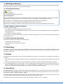
1. Wichtige Hinweise
Bitte lesen Sie vor der ersten Anwendung des Produktes bzw. dessen Einbau diese Bedienungsanleitung aufmerksam
durch. Bewahren Sie diese auf, sie ist Teil des Produktes.
1.1 Sicherheitshinweise
Vorsicht:
Verletzungsgefahr!
Für die Montage sind Werkzeuge nötig.
Stromschlaggefahr!
Die Anschlussdrähte niemals in eine Steckdose einführen! Verwendetes Versorgungsgerät (Transformator, Netzteil)
regelmäßig auf Schäden überprüfen. Bei Schäden am Versorgungsgerät dieses keinesfalls benutzen!
Alle Anschluss- und Montagearbeiten nur bei abgeschalteter Betriebsspannung durchführen!
Ausschließlich nach VDE/EN gefertigte Modellbahntransformatoren verwenden!
Stromquellen unbedingt so absichern, dass es bei einem Kurzschluss nicht zum Kabelbrand kommen kann.
1.2 Das Produkt richtig verwenden
Dieses Produkt ist bestimmt:
- Zum Einbau in Modelleisenbahnanlagen und Dioramen.
- Zum Anschluss an einen Modellbahntransformator (z. B. Art. 5200) bzw. an eine Modellbahnsteuerung mit zugelassener
Betriebsspannung.
- Zum Betrieb in trockenen Räumen.
Jeder darüber hinausgehende Gebrauch gilt als nicht bestimmungsgemäß. Für daraus resultierende Schäden haftet
der Hersteller nicht.
1.3 Packungsinhalt überprüfen
Kontrollieren Sie den Lieferumfang auf Vollständigkeit:
- Soundmodul mit blauer Leitung
- Montagematerial (2 Schrauben, 8 Stecker)
- Anleitung
2. Einleitung
Modellbahn mit allen Sinnen erleben: Das stationäre Soundmodul ergänzt die Szenen der Bewegten Welten um die
passenden Geräusche. Das Soundmodul verfügt über einen internen Lautsprecher und einen Anschluss für einen
externen Lautsprecher.
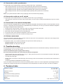
3. Einbau
Die Befestigung des Bausteins erfolgt mit den beiliegenden Schrauben. Für optimalen Klang beachten Sie folgende
Hinweise:
1. Der Lautsprecher ist im Modul integriert. Für eine gute Schallverteilung darf die Oberseite des Moduls nicht verdeckt
sein.
2. Soundmodul möglichst in Richtung der Zuschauer/Zuhörer ausrichten, also keine Über-Kopf-Montage unter der Anlage.
3. Das Soundmodul sollte sich dort befinden, wo das entsprechende Funktionsmodell auf Ihrer Anlage vorkommt. Sie
können das Modul auch auf der Anlage (z. B. in einem Gebäude etc.) einbauen. So erreichen Sie noch besseren
Klang und eine bessere Übereinstimmung von sichtbarer und hörbarer Geräuschquelle.
4. Anschluss
Geeignete Kabel: Der geringe Strombedarf des Soundmoduls erlaubt es, entsprechend dünn dimensionierte Kabel,
die sich gut versteckt verlegen lassen, zu verwenden. Wir empfehlen Litze mit einem Querschnitt von 0,14 mm² (z. B.
Viessmann Art. 6860 – 6869 oder 68603 – 68693).
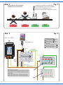
Zum automatischen Betrieb (Diorama-Modus) des Soundmoduls beachten Sie bitte Abb. 2 (Kennzeichnung B). Zum
manuellen Betrieb des Soundmoduls beachten Sie bitte Abb. 2 (Kennzeichnung A).
Ein Betrieb des Soundmoduls ist auch ohne das eMotion Modell „Jukebox“, Art. 1511 möglich.

3
4.1 Anschluss mit einem Taster
Zum Betrieb des Soundmoduls mit Taster beachten Sie bitte Abb. 2 (Kennzeichnung A).
- Nach einem Tastendruck wird der erste Song abgespielt (optional mit Synchronbewegung).
- Nach dem nächsten Tastendruck wird der zweite Song abgespielt (optional mit Synchronbewegung).
- Nach dem nächsten Tastendruck wird der dritte Song abgespielt (optional mit Synchronbewegung).
- Nach dem nächsten Tastendruck wird wieder der erste Song abgespielt (optional mit Synchronbewegung).
- Usw.
Hinweis: Drücken Sie während ein Song abgespielt wird die Taste, beendet das Soundmodul den Abspielvorgang.
4.2 Anschluss mit einem Umschalter
Zum Betrieb des Soundmoduls mit Umschalter beachten Sie bitte Abb. 2 (Kennzeichnung B).
- Die Reihenfolge ist gleich wie bei der Verwendung eines Tasters, aber die Songs werden alle zwei bis drei Minuten
automatisch abgespielt.
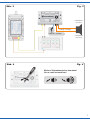
4.3 Anschluss eines externen Lautsprechers
Das Soundmodul verfügt über einen Ausgang für einen externen Lautsprecher mit den elektrischen Werten min. 8 Ohm
Impedanz und min. 1 Watt Leistung (erhältlich im Elektronik-Fachhandel). Bei Anschluss eines externen Lautsprechers
wird der eingebaute Lautsprecher ausgeschaltet.
1. Ziehen Sie das kurze blaue, am Soundmodul befindliche Kabel aus der Buchse rechts daneben.
2. Isolieren Sie das blaue Kabel, so dass es keinen Kontakt mit anderen Kabeln haben kann.
3. Montieren Sie den externen Lautsprecher am vorgesehenen Einbauort.
4. Verlegen Sie die beiden Anschlussleitungen des externen Lautsprechers zum Soundmodul.
5. Verbinden Sie die Anschlussleitungen mit den beiden Buchsen gemäß Abb. 3.
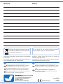
4.4 Lautstärke einstellen
Sie können die Wiedergabelautstärke des Soundmoduls einstellen. Diese Einstellung gilt sowohl für den eingebauten als auch
für einen alternativ vorhandenen externen Lautsprecher.
Zum Einstellen der Lautstärke verwenden Sie bitte einen geeigneten Schraubendreher (Schlitz), wie in Abb. 4 gezeigt:
- Lauter: Drehen Sie das Potentiometer nach rechts.
- Leiser: Drehen Sie das Potentiometer nach links.
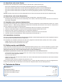
5. Fehlersuche und Abhilfe
Jedes Viessmann-Produkt wird unter hohen Qualitätsstandards gefertigt und vor seiner Auslieferung geprüft. Sollte
es dennoch zu einer Störung kommen, können Sie anhand der folgenden Punkte eine erste Überprüfung vornehmen.
Überprüfen Sie bitte als erstes die Stromzuführungen und die Verkabelung.
Soundmodul spielt keinen Sound ab. Am externen Lautsprecher ist kein Sound zu hören.
- Soundmodul muss nach Abb. 2 angeschlossen sein. Wenn der Synchroneingang nicht wie in den Abbildungen belegt
ist, kann kein Sound abgespielt werden!
- Poti nach rechts drehen.
- Stellen Sie sicher, dass der kleine blaue Stecker am unteren Gehäuserand des Soundmoduls aus der Buchse daneben
entfernt und isoliert ist.
Schließen Sie den externen Lautsprecher gemäß Abb. 3 an.
Wenn Sie die Fehlerursache nicht finden und beheben können, nehmen Sie bitte Kontakt mit uns auf (service@viessmann-
modell.com). Senden Sie uns den Artikel zur Kontrolle bzw. Reparatur bitte erst nach Rücksprache zu.
6. Technische Daten
Betriebsspannung: 10 – 16 V AC ~ / 14 – 24 V DC =
Betriebsstrom: ca. 150 mA
Schutzklasse/Isolation: IP20
Temperatur/Feuchtigkeit (Betrieb): 0 – 40° C
Temperatur/Feuchtigkeit (Lager): -10 – 60° C
Gewicht: ca. 50 g
Maße: L 8,8 x B 5,3 x H 2,2 cm

4
1. Important information
Please read this manual completely and attentively before using the product for the rst time. Keep this manual. It is part
of the product.
1.1 Safety instructions
Caution:
Risk of injury!
Tools are required for installation.
Electrical hazard!
Never put the connecting wires into a power socket! Regularly examine the transformer for damage. In case of any
damage, do not use the transformer.
Make sure that the power supply is switched off when you mount the device and connect the cables!
Only use VDE/EN tested special model train transformers for the power supply!
The power sources must be protected to avoid the risk of burning cables.
1.2 Using the product for its correct purpose
This product is intended:
- For installation in model train layouts and dioramas.
- For connection to an authorized model train transformer (e. g. item 5200) or a digital command station.
- For operation in dry rooms only.
Using the product for any other purpose is not approved and is considered inappropriate. The manufacturer is not re-
sponsible for any damage resulting from the improper use of this product.
1.3 Checking the package contents
Check the contents of the package for completeness:
- Sound module with blue cable
- Mounting material (2 screws, 8 plugs)
- Manual
2. Introduction
Experience the model railway with all your senses: The stationary sound module provides the specic sounds to the
scenes in the animated world. The sound module is equipped with integral loudspeaker and connection for an external
loudspeaker.
3. Mounting
Fasten the module with the enclosed screws. To ensure an optimal sound reproduction of the module, please note the
following hints:
1. The loudspeaker is an integral part of the module. The upper surface of the module must always be uncovered in
order to provide a good sound dispersion.
2. If possible, gear the sound module towards the spectator, so please avoid upside down mounting under the layout.
3. The sound module should be installed near the respective functional model on your layout. You can also install the
module on the layout, e. g. in a building. This way you can even have a better sound and an optimal concordance
between the visible and the audible sound source.
4. Connection
Fitting cables: Due to the low current consumption thin cables can be used which can easily be hidden. It is recom-
mended to use a cross section of 0.14 mm² (e. g. Viessmann items 6860 – 6869 or 68603 – 68693).
For automatic operation (diorama mode) of the sound module, please refer to g. 2 (section B). For manual operation of
the sound module, please refer to g. 2 (section A).
It is also possible to operate the sound module without the eMotion model “Jukebox”, item 1511.

5
4.1 Connection with a push-button
To operate the sound module with a push-button, please refer to g. 2 (marking A).
- After pushing the button, the first song is played (optionally with synchronous movement).
- After pushing the button, the second song is played (optionally with synchronous movement).
- After pushing the button, the third song is played (optionally with synchronous movement).
- After pushing the button, the first song is played again (optionally with synchronous movement).
- Etc.
Note: If you press the button while a song is playing, the sound module stops playing.
4.2 Connection with an on-off switch
To operate the sound module with an on-o switch, please refer to g. 2 (marking B).
- The sequence is the same as when using a push-button, but the songs are played automatically every two to three
minutes.
4.3 Connection of an external loudspeaker
The sound module is equipped with an output for an external loudspeaker with electrical values of 8 ohm impedance at least
and min. 1 watt power (can be purchased in a specialized shop for electronics). In case you connect an external loudspeaker
the integral loudspeaker will be switched o.
1. Please pull the sound module’s short blue cable out of the next socket to the right.
2. Insulate the blue cable to avoid any contact with other cables.
3. Mount the external loudspeaker to the intended place.
4. Lay the two wires of the external loudspeaker to the sound module.
5. Connect the two wires to the two sockets according to fig. 3.
4.4 Volume adjustment
The sound module is equipped with a volume control for the sound. The adjustment is valid both for the integral loud-
speaker and for an external loudspeaker.
To adjust the volume, use a slotted screwdriver and proceed as follows (see g. 4):
- Increase volume: Turn the poti to the right.
- Reduce volume: Turn the poti to the left.
5. Trouble-shooting
All Viessmann products are produced with high quality standards and are checked before delivery. Should a fault occur
nonwithstanding, you can do a rst check.
Please check rst the power supply and the wiring.
No sound from the module. No sound from the external loudspeaker.
- Sound module has to be connected acc. to fig. 2. If the synchronous input is not connected as shown in the figures,
playing of the sound will not be possible!
- Turn the poti to the right.
- Please make sure that the small blue plug at the housing of the sound module is removed from the socket and is
insulated.
Connect the external loudspeaker as shown in fig. 3.
If you are unable to nd and x the cause for the problem please contact our service department (service@viessmann-
modell.com). Please send the item to the Viessmann service department for check and repair only after consultation.
6. Technical data
Operation voltage: 10 – 16 V AC ~
14 – 24 V DC =
Operation current: ca. 150 mA
Insulation: IP20
Temperature/humidity (operation): 0 – 40° C
Temperature/humidity (storage): -10 – 60° C
Weight: ca. 50 g
Dimensions: L 8.8 x W 5.3 x H 2.2 cm

6
Sekundär
0-10-16 V~
16 V
Primär
230 V~
Gefertigt nach
VDE 0570
EN 61558
Lichttransformator
5200
Nur für trockene Räume
Primär 230 V 50 - 60 Hz
Sekundär max. 3,25 A52 VA
ta 25°CIP 40
10 V
0 V
viessmann 5550
Universal Ein-Aus-Umschalter
gelb
braun
z. B. / e. g. 5200
grün
z. B. / e. g. 5550
Gleichspannungsbetrieb:
Synchroneingang mit Pol der
Spannungsquelle verbinden.
Synchroneingang mit Pol der
Spannungsquelle verbinden.
5578
Universal Tasten - Stellpult
5547
Viessmann
braun
1511 optional
/ brown
/ yellow
/ green
DC operation:
Connect “Synchroneingang” to
pole of the power supply.
Connect “Synchroneingang” to
pole of the power supply.
brown
Gleichspannungsbetrieb:
Braunes Kabel: mit + Pol der Spannungsquelle verbinden.
Gelbes Kabel: mit - Pol der Spannungsquelle verbinden.
DC operation:
Brown cable: connect to the + pole of the power supply.
Yellow cable: connect to the - pole of the power supply.
gelb
yellow
schwarz
black
Fig. 2
Abb. 2
A
B
Einbaulage für Soundmodule
Mounting of sound modules
Lautsprecherschlitze nicht abdecken!
Mit Lautsprecher nach oben montieren!
Do not cover loudspeaker slots!
Mount the module with loudspeaker on top!
Falsch RichtigFalsch
wrong correctwrong
Optimal
ideal
Fig. 1
Abb. 1

7
Sekundär
0-10-16 V~
16 V
Primär
230 V~
Gefertigt nach
VDE 0570
EN 61558
Lichttransformator
5200
Nur für trockene Räume
Primär 230 V 50 - 60 Hz
Sekundär max. 3,25 A52 VA
ta 25°CIP 40
10 V
0 V
viessmann 5550
Universal Ein-Aus-Umschalter
orange
isolieren
Lautsprecher
(min. 8 Ω)
/ orange
/ insulate
Loudspeaker
(min. 8 Ω)
Fig. 3
Abb. 3
Kleinen Schraubendreher benutzen!
Use a small screwdriver!
Fig. 4
Abb. 4

8
Änderungen vorbehalten. Keine Haftung für Druckfehler
und Irrtümer.
Die aktuelle Version der Anleitung finden Sie auf der Viess-
mann Homepage unter der Artikelnummer.
Subject to change without prior notice. No liability for
mistakes and printing errors.
You will nd the latest version of the manual on the Viess-
mann website using the item number.
Entsorgen Sie dieses Produkt nicht über den
(unsortierten) Hausmüll, sondern führen Sie
es der Wiederverwertung zu.
Do not dispose of this product through (unsorted)
domestic waste, supply it to recycling instead.
Modellbauartikel, kein Spielzeug! Nicht geeignet für
Kinder unter 14 Jahren! Anleitung aufbewahren!
Model building item, not a toy! Not suitable for children
under the age of 14 years! Keep these instructions!
Ce n’est pas un jouet! Ne convient pas aux enfants de
moins de 14 ans! Conservez cette notice d’instructions!
Não é um brinquedo! Não aconselhável para menores de
14 anos! Conservar o manual de instruções!
Modelbouwartikel, geen speelgoed! Niet geschikt voor
kinderen onder 14 jaar! Gebruiksaanwijzing bewaren!
Articolo di modellismo, non è un giocattolo! Non adatto
a bambini al di sotto dei 14 anni! Conservare istruzioni per
l’uso!
Artículo para modelismo ¡No es un juguete! No
recomendado para menores de 14 años! Conserva las
instrucciones de servicio!
DE
EN
FR
NL
IT
ES
PT
Made in Europe
Viessmann
Modelltec
hnik GmbH
Bahnhofstraße 2a
D - 35116 Hatzfeld-Reddighausen
+49 6452 9340-0
www.viessmann-modell.de
80843
Stand 01/sw
04/2022
Ho/Kf
Notizen Notes
-
 1
1
-
 2
2
-
 3
3
-
 4
4
-
 5
5
-
 6
6
-
 7
7
-
 8
8


