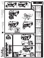
Schneider Electric TeSys U - LUCM/LUCMT Multifunction control unit Instruction Sheet
- Tipo
- Instruction Sheet

B
7 mm
L
0,5 N.m
Ø3,5 mm Ø3 mm
0.27 in. 5 lb-in.
Ø0.125 in. Ø0.12 in.
0,2...1,5 mm
22
0,25...1,5 mm 0,2...1,5 mm
2 2
0,2...1 mm
AWG 24...16 AWG 24...16 AWG 24...18 AWG 24...16 AWG 24...18
0,2...1 mm
2
24V c
www.schneider-electric.com
LUCM
AAV40504
DANGER / DANGER / GEFAHR / PELIGRO / PERICOLO / ОПАСНО /
A
LUB12 / LUB32
LUB120 / LUB320
AAV40504-06
12 - 2020
1/6
LU9BN11
C
4
3
1
2
Crack!
5
Click! D
Click!
3
6
A
HAZARD OF ELECTRIC
SHOCK, EXPLOSION, OR
ARC FLASH
Disconnect all power
before servicing
equipment.
Failure to follow these
instructions will result in
death or serious injury.
RISQUE D'ÉLECTROCUTION,
D'EXPLOSION OU D'ECLAIR
D'ARC ELECTRIQUE
Coupez toutes les alimentations
avant de travailler sur cet
appareil.
Le non-respect de ces
instructions provoquera la mort
ou des blessures graves.
GEFAHR VON ELEKTRISCHEM
SCHLAG, EXPLOSION ODER
LICHTBOGEN
Vor dem Arbeiten am Gerät alle
Spannungsversorgungen
abschalten.
Die Nichtbeachtung dieser
Anweisungen führt zu Tod
oder schwereren Verletzungen.
PELIGRO DE DESCARGA
ELÉCTRICA, EXPLOSIÓN O
ARCO ELECTRICO
Desconecte todas las aliment-
aciónes antes de manipular el
producto.
Si no se siguen estas instruccio-
nes provocará lesiones graves o
incluso la muerte.
RISCHIO DI SCARICA
ELETTRICA , ESPLOSIONE O
ARCO ELETTRICO
Scollegare l’apparecchio da tutti
i circuiti di alimentazione prima
di qualsiasi intervento.
Il mancato rispetto di queste
istruzioni provocherà morte o
gravi infortuni.
Опасность поражением
электрическим током, опасность
взрыва или вспышки дуги.
Перед обслуживанием или
ремонтом убедитесь, что питание
отключено.
Несоблюдение этих инструкций
приведет к смерти или
серьезной травме.
Schneider Electric Ltd, Stafford Park5,
Telford, TF3 3 BL, UK
UK Importer
Schneider Electric Industries SAS
35, rue Joseph Monier
92506 Rueil Malmaison France
Manufacturer

AAV40504-06
E
2/6
(read with possibility to enter password)
(read only)/
(read and write)/
(read and write)
(read only)/
(read only)/
(read only)/
(read only)/
(read only)/
(read and write)/
(read and write)/
(read only)/
(read only)/
(read only)/
OFF/
Ready/
Pause/
Run/
or/ou/oder/o/o/
1_Reference/
11_Catalog/
2_Display/
21_AvCurrent/
3_SetUp/
31_FLASet
4_AdvSetUp/
41_Trip Class/
5_CommSetUp/
51_Drop/
6_Module/
61_ID Clear/ID
7_Statistics/
71_Trip0/0
8_Password/
81_Unlock/
- - -
84_RstToDfts 84_RstToDfts
= No/=
? Yes/?
Language/
= English/=
LoadType/
= 3 Ph Motor/= 3
PowerBase/
= SelfProtStr
AuxFan/
= No/=
EndConfig/
= No/=
? Yes/?
LR Conf/
= Remote/=
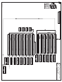
Main menu/Menu/Menu/Hauptmenu/Principale/
1_Reference/Profil/Info/Profil/Profilo/
Main menu/Menu/Menu/Hauptmenu/Principale/
2_Display/Afficher/Visualizar/Anzeigen/Visualizza/
Main menu/Menu/Menu/Hauptmenu/Principale/
3_SetUp/Régler/Configurar/Einstellen/Setup/
Main menu/Menu/Menu/Hauptmenu/Principale/
4_AdvSetUp/Paramétrer/Ajustar/Parameter/Parametr./
Main menu/Menu/Menu/Hauptmenu/Principale/
5_CommSetUp/Echanger/Com.conf./Austausch/Scambia/
Main menu/Menu/Menu/Hauptmenu/Principale/
6_Module/Module/Módulo/Modul/Modulo/
Main menu/Menu/Menu/Hauptmenu/Principale/
7_Statistics/Historique/Histórico/Statistik/Statistich/
Main menu/Menu/Menu/Hauptmenu/Principale/
8_Password/Code accès/Código/Passwort/Password/
Config Menu/Configurer/Configurar/Konfigur./Imposta/
Language/Langue/Idioma/Sprache/Lingua/
Config Menu/Configurer/Configurar/Konfigur./Imposta/
LoadType/Charge/Carga/Lastart/Carico/
Config Menu/Configurer/Configurar/Konfigur./Imposta/
Base Type/Base/Tipo Base/Grundger./Tipo base/
Config Menu/Configurer/Configurar/Konfigur./Imposta/
AuxFan/Motovent/Aux.Vent/Fremdbel./Servovent/
Config Menu/Configurer/Configurar/Konfigur./Imposta/
EndConfig/Fin/Fin/Beenden/Uscita/
Config Menu/Configurer/Configurar/Konfigur./Imposta/
LR Conf/
Off /A l'arrêt/Paro/Bereit/Off/
or/ou/oder/o/o/
or/ou/oder/o/o/
www.schneider-electric.com
TeSys U LUCM
ref : 1743237
TeSys U LUCM
Config Menu
Language

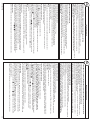
Control power connections
Auxiliary power 24V DC input is required for:
b Initial configuration and setting before installation into a power base type.
b Operation of remote and auto-reset function with 3-wire control.
b Modification of settings or displaying of fault statistics in the Off, Trip or Fault modes.
b Communicating through the RS-485 communication port.
NOTE:
b All control connections must be of proper polarity for correct operation.
b Without auxiliary control power, cycling of control power to terminals A1, A2 will reset all Remote
re-settable faults.
Minimum required setup
1. Supply power to the auxiliary power input 24V DC.
2. Press , to enter the Config Menu.
3. Validate the functions (Language, LoadType, Base Type, CT_Ratio, Aux Fan) that define the
Multifunction Control Unit profile. (see Menu page 3)
4. Enable the End Config function to enter the Main Menu.
5. In the Main Menu, press to scroll to the 3_Setup submenu. Enter into the 31_FLASet
by pressing the key.
6. In the 31_FLASet function, press or to scroll to the desired full load motor
current value per the name plate markings on the motor. Press to validate setting.
NOTE:
b All the others functions and parameters are set to their default values.
b For use with single and three-phase AC electric motors only.
b For configuration by means of the RS-485 communication port, see the LUCM user manual.
Adjustment of settings
b Adjustment to Protection function setting in 3_Setup can be made when the main power contacts are
closed (with coil control power applied to terminals A1, A2) or open (without coil control power applied
to terminals A1, A2).
b Adjustment to Protection function setting in 4_AdvSetup can only be made when the main power
contacts are open (without coil control power applied to terminals A1, A2).
b To begin the adjustment of a setting, press , press , or to scroll to the desired sub-menu.
Test trip
The test trip orders can be only performed when the motor-starter is running.
3/6
AAV40504-06
Alimentation auxiliaire
L'alimentation auxiliaire 24V DC est necessaire pour réaliser :
b La configuration initiale et les réglages.
b Le réarmement à partir du clavier ou le mode de réarmement automatique dans le cas
d'une commande 3 fils.
b La modification des réglages ou l'affichage des statistiques à l'état OFF, déclenché ou défaut.
b La communication par le port RS-485.
NOTA :
b Pour le bon fonctionnement de l'équipement, toutes les connexions de contrôle doivent avoir
la polarité appropriée.
b Sans alimentation auxiliaire, l’activation/désactivation de l’alimentation au niveau des bornes A1 et A2 réarmera tous
les défauts réglables à distance.
Mise en route rapide
1. Raccorder l'alimentation auxiliaire 24V DC.
2. Appuyer sur la touche pour accéder au menu Configurer.
3. Renseigner les fonctions qui définissent le profil de l'unité de contrôle multifonction (voir menu page 3).
4. Valider par la fonction Fin pour accéder au Menu principal.
5. Dans le Menu principal, à l'aide de la touche faire défiler les menus jusqu'au menu 3_Régler et appuyer sur la
touche pour y entrer. Appuyer sur la touche pour accéder aux paramètres de la fonction 31_Ir moteur.
6. Sélectionner la valeur du courant nominal à pleine charge correspondant à la valeur plaquée sur le moteur en utilisant
les touches ou .
NOTA :
bToutes les autres fonctions et paramètres sont réglés avec les valeurs par défaut (sortie d'usine).
b Utilisation uniquement avec moteurs électriques monophasés et triphasés CA.
b Pour plus d'informations sur la configuration avec le port de communication RS-485, se reporter au manuel
d'utilisation LUCM.
Réglage des paramètres
b Le réglage de la fonction de protection du menu 3_Régler peut être réalisé moteur en marche
(A1, A2 alimentées) ou moteur à l'arrêt (A1, A2 non alimentées).
b Le réglage des fonctions de protection du menu 4_Paramétrer ne peut être réalisé que si le moteur est à l'arrêt (A1,
A2 non alimentées).
b Pour réaliser le réglage de ces paramètres, accéder aux menus désirés en utilisant
les touches , , .
Test de déclenchement
Les ordres de test de déclenchement ne sont pris en compte que lorsque le démarreur est en marche.
ENT
ENT
ENT
ENT
en fr
b Turn of all power supplying this equipment before working on it.
b To maintain over-current, short-circuit and ground-fault protection:
v The selection and settings of over-current protection must conform with national and local
safety regulations and codes.
v The FLA adjustement must be set to match the Full Load Amp rating and heating characteristics
of the motor.
v Ground fault and phase imbalance levels must be set to protect wiring and motor equipment.
Failure to follow these instructions can result in death, serious injury, or equipment damage.
LOSS OF PROTECTION - RISK OF FIRE OR ELECTRICAL SHOCK
UNINTENTED MOTOR STARTING
To prevent unintended motor starting:
b Equipment operation must conform with national and local safety regulations and codes.
b The PauseMtr function should never be used in place of a Stop or Off command.
b Components that disconnect power, such as E-stop or limit switches, must only be connected
to the positive (+) coil control terminal, A1.
Failure to follow these instructions can result in death, serious injury, or equipment damage.
b Mettre toutes les sources d'alimentation de l'équipement hors tension avant toute opération.
b Pour maintenir la protection en cas de surintensité, de court-circuit ou de défaut de mise à la terre :
v La sélection et le réglage de la protection en cas de surintensité doivent être conformes
aux réglementations et codes nationaux et locaux en matière de sécurité.
v Le réglage du paramètre Ir doit correspondre au courant nominal à pleine charge du moteur
et aux caractéristiques thermiques du moteur.
v Les seuils de défaut de mise à la terre et de déséquilibre des phases doivent être réglés de manière
à protéger le câblage et l'équipement du moteur.
Le non-respect de ces instructions peut provoquer la mort, des blessures graves ou des dommages matériels.
SUPPRESSION DE LA PROTECTION – RISQUES DE CHOC ÉLECTRIQUE OU D'INCENDIE
DÉMARRAGE INTEMPESTIF DU MOTEUR
Pour empêcher tout démarrage intempestif du moteur :
b Le fonctionnement de l'équipement doit être conforme aux réglementations et codes nationaux
et locaux en matière de sécurité.
b La fonction Pause ne doit jamais être utilisée comme commande d'arrêt.
b Les composants qui peuvent couper l'alimentation, comme l'arrêt d'urgence ou les interrupteurs
de position, doivent être connectés uniquement à la borne positive (+) A1 de la bobine de commande.
Le non-respect de ces instructions peut provoquer la mort, des blessures graves ou
des dommages matériels.
WARNING AVERTISSEMENT
ENT
ENT
ENT
ENT

4/6
AAV40504-06
Steueranschlüsse
Eine 24V DC-Hilfsversorgung ist erforderlich für:
b Erstkonfiguration und -einstellung vor Installation in ein Leistungsteil.
b Betrieb der Remote- und Auto-Reset-Funktion mit 3-Draht-Steuerung.
b Modifikation der Einstellungen oder Anzeige der Fehlerstatistik im Modus Off, Trip oder Fault (Fehler).
b Kommunikation über RS-485 Kommunikations-Schnittstelle.
HINWEIS:
b Alle Steueranschlüsse müssen für korrekten Betrieb richtig gepolt sein.
b Ohne Steuerungs-Hilfsversorgung werden beim Aus- und Wiedereinschalten der Stromversorgung
zu den Klemmen A1, A2 alle per Remote Reset rückstellbaren Fehler zurückgesetzt.
Minimal erforderlicher Setup
1. Stromversorgung zum 24V DC Hilfseingang.
2. drücken, um in das Konfig Menu zu gelangen.
3. Funktionen validieren (Sprache, Lastart, Grundger.,CT_Ratio, Fremdbel) mit denen das Profil des
Multifunktions-Steuergeräts definiert wird. (siehe Menü Seite 3)
4. Funktion End Config freigeben, um ins Hauptmenü zu gelangen.
5. Im Hauptmenü drücken, um zum Untermenü 3_Einstellen zu scrollen. Taste drücken,
um ins 31_lr Motor zu gelangen.
6. In der Funktion 31_lr Motor oder drücken, um zum gewünschten, auf dem Typenschild
angegebenen, Wert für den Volllast-Motorstrom zu gelangen. drücken, um die Einstellung zu validieren.
HINWEIS:
b Alle anderen Funktionen und Parameter werden auf ihre Standardwerte eingestellt.
b Nur bei Verwendung einphasiger und dreiphasiger Elektromotoren.
b Zur Konfiguration über die RS-485 Kommunikations-Schnittstelle, siehe LUCM Bedienungsanleitung.
Durchführung der Einstellungen
b Die Schutzfunktions-Einstellung in 3_Einstellen kann durchgeführt werden, wenn die
Netzversorgungskontakte geschlossen (mit Spulen-Steuerspannung an Klemmen A1, A2) oder geöffnet
sind (ohne Spulen-Steuerspannung an Klemmen A1, A2).
b Die Schutzfunktions-Einstellung in 4_Parameter kann nur durchgeführt werden, wenn die
Netzversorgungskontakte geöffnet sind (ohne Spulen-Steuerspannung an Klemmen A1, A2).
b Drücken Sie zu Beginn der Einstellung , drücken Sie oder , um zum gewünschten Untermenü
zu scrollen.
Test Trip (Auslösung)
Befehle für eine Test-Auslösung können nur durchgeführt werden, wenn der Motor-Starter läuft.
b Schalten Sie jegliche Stromversorgung zu diesem Gerät aus, bevor Sie an ihm arbeiten.
b Zur Aufrechterhaltung des Überstrom-, Kurzschluss- und Erdschluss-Schutzes:
v Auswahl und Einstellungen des Überstromschutzes müssen nationalen und lokalen Sicherheitsbestimmungen
und Gesetzen entsprechen.
v Die Volllaststrom-Einstellung muss entsprechend dem Volllaststrom-Nennwert und der
Erwärmungskennlinie des Motors vorgenommen werden.
v Zulässiger Erdschlussfehler und Phasenabweichung müssen so eingestellt sein, dass Verkabelung
und Motorausrüstung geschützt sind.
Die Nichtbefolgung dieser Anweisungen kann zu tödlichen oder schweren Verletzungen oder zu Schäden
an den Geräten führen.
VERLUST DES SCHUTZES - BRAND- ODER STROMSCHLAGGEFAHR
UNBEABSICHTIGTER MOTORSTART
Um einen unbeabsichtigten Motorstart zu verhindern:
b Muss der Betrieb der Geräte mit nationalen und lokalen Sicherheitsvorschriften und Gesetzen übereinstimmen.
b Sollte die Funktion PauseMtr niemals anstelle eines Stop- oder Off-Befehls verwendet werden.
b Komponenten, die Leistung trennen, wie z.B. Not-Aus- oder Grenzwertschalter, dürfen nur an die
positive (+) Spulen-Steuerklemme A1 angeschlossen werden.
Die Nichtbefolgung dieser Anweisungen kann zu tödlichen oder schweren Verletzungen oder zu Schäden
an den Geräten führen.
WARNUNG AVVERTENZA
ENT
ENT
ENT
ENT
Collegamenti elettrici di comando
L’alimentazione ausiliaria a 24V DC serve per realizzare:
b Configurazione e regolazioni iniziali prima dell’installazione in una base di potenza.
b Il riarmo effettuato agendo sulla tastiera o la modalità di riarmo automatico in caso di comando a 3 fili.
b La modifica delle regolazioni o la visualizzazione delle statistiche in condizioni di disattivazione,
disinnesto o guasto.
b La comunicazione dalla porta RS-485.
NOTA:
b Ai fini di un buon funzionamento tutti i collegamenti di controllo devono avere la corretta polarità.
b Senza l’alimentazione di comando ausiliaria, attivando e disattivando l’alimentazione diretta ai morsetti
A1, A2 tutti i guasti remoti ripristinabili si azzerano.
Messa in funzione rapida
1. Collegare l’alimentazione ausiliaria a 24V DC.
2. Premere il pulsante per accedere al menu Imposta.
3. Identificare le funzioni (Lingua, Carico, Tipo base,Servovent, IT_Ratio) che definiscono il profilo
dell’unità di comando multifunzioni. (vedere Menu, pagina 3)
4. Confermare tramite la funzione Uscita per accedere al menu principale.
5. Nel menu principale, agendo sul tasto scorrere i menu fino alla visualizzazione del menu 3_Setup.
Premere il tasto per accedere ai parametri della funzione 31_lr moteur.
6. Nella funzione 31_lr moteur, selezionare il valore della corrente nominale a pieno carico,
corrispondente al valore riportato sulla targa del motore, utilizzando il tasto o .
NOTA:
b Tutte le altre funzioni e parametri sono regolati in base a valori predefiniti.
b Da utilizzare esclusivamente con motori elettrici monofase e trifase AC.
b Per la configurazione mediante la porta di comunicazione RS-485, consultare il manuale per l’utente LUCM.
Regolazione dei parametri
b La regolazione della funzione di protezione del menu 3_Setup può essere effettuata con il motore in
funzione (A1, A2 alimentate) o in fase d’arresto (A1, A2 non alimentate).
b La regolazione della funzione di protezione del menu 4_Parametri può essere effettuata solamente
se il motore è in fase d’arresto (A1, A2 non alimentate).
b Per effettuare la regolazione di tali parametri accedere ai menu desiderati agendo sui tasti o o .
Test di avviamento
Gli ordini di test di avviamento vengono eseguiti solo quando il dispositivo di avviamento è in funzione.
b Scollegare l’apparecchio dalla presa di corrente prima di qualsiasi intervento.
b Per mantenere la protezione da sovracorrente, corto circuito e guasto di terra:
v La selezione e le regolazioni della protezione da sovracorrente devono essere conformi alle normative e
ai codici nazionali e locali di sicurezza.
v La regolazione della corrente nominale a pieno carico deve essere stabilita secondo l'amperaggio a pieno
carico e le caratteristiche di riscaldamento del motore.
v I livelli di guasti di terra e di squilibrio di fase devono essere regolati per proteggere il cablaggio e
le apparecchiature a motore.
Il mancato rispetto di queste istruzioni può causare morte, gravi lesioni o danni alle apparecchiature.
PERDITA DI PROTEZIONE – RISCHIO DI INCENDIO O SCOSSE ELETTRICHE
AVVIAMENTO ACCIDENTALE
Per prevenire l’avviamento accidentale del motore:
b L’utilizzo delle apparecchiature deve essere conforme alle normative e ai codici nazionali e locali di sicurezza.
b La funzione Pause non deve mai essere utilizzata con funzione di comando d’arresto.
b I componenti di interruzione di corrente, quali pulsanti d’arresto d’emergenza (E-stop) ed interruttori
di fine corsa, devono essere collegati solo al morsetto di comando A1 avvolgimento positivo (+).
Il mancato rispetto di queste istruzioni può causare morte, gravi lesioni o danni alle apparecchiature.
ENT
ENT
ENT
de it

5/6
AAV40504-06
Conexiones de alimentación de control
Se necesita una entrada de alimentación auxiliar de 24 V CC para:
b La configuración y el ajuste inicial antes de la instalación en un tipo de base de potencia.
b El funcionamiento de la función remota y de reinicio automático con control de tres hilos.
b La modificación de la configuración o la visualización de estadísticas de fallos en los modos
desactivado, de disparo o de fallo.
b La comunicación a través del puerto de comunicación RS-485.
NOTA:
b Todas las conexiones de control deben conectarse con la polaridad adecuada para que funcionen
correctamente.
b Sin alimentación de control auxiliar, el ciclo de alimentación de control para los terminales A1, A2
borrará todos los fallos rearmables remotos.
Configuración mínima necesaria
1. Suministre corriente a la entrada de alimentación auxiliar de 24 V CC.
2. Pulse para entrar en el menú Configurar.
3. Valide las funciones (Idioma, Carga, Tipo Base, CT_Ratio, Aux. Vent) que definen el perfil Unidad de
control multifunción (véase el menú de la página 3).
4. Active la función Fin para abrir el menú principal.
5. En el menú principal, pulse para desplazarse hasta el submenú 3_Configurar. Acceda a 31_lr motor
pulsando la tecla .
6. En la función 31_lr motor, pulse o para desplazarse hasta el valor de corriente del motor a plena
carga deseado, de acuerdo con las marcas de nombre de placa del motor. Pulse para validar
la configuración.
NOTA:
b Todos los demás parámetros y funciones se establecen en los valores predeterminados.
b Para uso exclusivo con motores eléctricos de CA monofásicos o trifásicos.
b Para la configuración a través del puerto de comunicación RS-485, consulte el manual del usuario de LUCM.
Ajuste de valores
b El ajuste de la función de protección en 3_Configurar se puede llevar a cabo cuando los contactos
de potencia principales están cerrados (con tensión de mando de la bobina aplicada a los terminales
A1, A2) o abiertos (sin tensión de mando de la bobina aplicada a los terminales A1, A2).
b El ajuste de la función de protección en 4_Ajustar sólo se puede llevar a cabo cuando los contactos
de potencia principales están abiertos (sin tensión de mando de la bobina aplicada a los terminales A1, A2).
b Para comenzar el ajuste de un valor, pulse , o para desplazarse hasta el submenú deseado.
Disparo de prueba
Las órdenes de disparo de prueba sólo se pueden realizar cuando el arrancador de motores está en marcha.
b Desconecte la alimentación de este equipo antes de manipularlo.
b Para mantener la protección contra la sobreintensidad, los cortocircuitos y los fallos a tierra:
v La selección y la configuración de la protección contra la sobreintensidad debe ajustarse a las normativas y
los códigos nacionales y locales.
v El ajuste de IPC debe corresponder con la corriente de carga máxima nominal y las características de
calentamiento del motor.
v Deben ajustarse los niveles de fallo a tierra y de desequilibrio de fases para proteger el cableado y el equipo del motor.
Si no se siguen estas instrucciones pueden producirse daños en el equipo, lesiones personales
graves o incluso la muerte.
PÉRDIDA DE PROTECCIÓN: RIESGO DE INCENCIO O DESCARGA ELÉCTRICA
ARRANQUE NO DESEADO DEL MOTOR
Para evitar el arranque no deseado del motor:
b El funcionamiento del equipo debe ajustarse a las normativas y los códigos nacionales y locales.
b La función Pausa no debe usarse nunca en lugar de un comando de parada o de apagado.
b Los componentes que desconectan la alimentación, como la parada de emergencia o los finales de carrera,
sólo deben conectarse al terminal positivo (+) del mando de la bobina, A1.
Si no se siguen estas instrucciones pueden producirse daños en el equipo, lesiones personales graves
o incluso la muerte.
ADVERTENCIA ПРЕДУПРЕЖДЕНИЕ
ENT
ENT
ENT
ENT
Соединения управляющего питания
Дополнительное питание 24 В постоянного тока требуется для:
b Начального конфигурирования и настройки перед установкой в питающую базу.
b Управления функциями удаленного управления и автоматического сброса с помощью трехпроводного
управления.
b Изменения настроек или отображения статистики ошибок в режимах Off (Выкл.), Trip (Разъединить) или
Fault (Ошибка).
b Связи через коммуникационный порт RS-485.
ПРИМЕЧАНИЕ:
b Для правильной работы все управляющие соединения должны быть подключены с соблюдением полярности.
b Без дополнительного управляющего питания зацикливание управляющего питания на зажимах А1 и А2
приведет к сбросу всех удаленных сбрасываемых ошибок.
Минимальная требуемая настройка
1. Подача питания на вход дополнительного питания 24 В постоянного тока
2. Нажмите , чтобы войти в меню Config Menu (Меню конфигурации).
3. Проверьте функции (Language (Язык), LoadType (Тип нагрузки), Base Type (Тип основания),
CT_Ratio (Коэфф. трансформации), Aux Fan (Вспомогательный вентилятор)), определяющие
профиль многофункционального устройства управления (см. страницу меню 3).
4. Включите функцию End Config (Конечная конфигурация), чтобы войти в Main Menu (Главное меню).
5. В Main Menu (Главное меню) нажмите , чтобы перейти к подменю 3_Setup. Войдите в меню
31_FLASet, нажав клавишу .
6. меню функции 31_FLASet нажмите или для перехода к требуемому значению тока при
максимальной нагрузке двигателя, указанной в маркировке на заводской табличке двигателя.
Нажмите для подтверждения настройки.
ПРИМЕЧАНИЕ:
b Для всех других функций и параметров устанавливаются значения по умолчанию.
b Только для использования в однофазных и трехфазных электродвигателях переменного тока.
b Для настройки с помощью коммуникационного порта RS-485 см. Руководство по эксплуатации LUCM.
Изменение настроек
b Настройку функции Protection (Защита) в 3_Setup можно изменить, если контакты питания от сети
замкнуты (управляющее питание катушки подается на зажимы А1, А2) или разомкнуты (управляющее
питание катушки не подается на зажимы А1, А2).
b Настройку функции Protection (Защита) в 4_AdvSetup можно изменить только в том случае, если
контакты питания от сети разомкнуты (управляющее питание катушки не подается на зажимы А1, А2).
b Чтобы изменить настройку, нажмите , затем нажмите или для перехода к требуемому подменю.
Проверочное расцепление
Команды проверочного расцепления могут выполняться только во время работы пускателя двигателя.
b Прежде чем начать работу с оборудованием, полностью отключите электропитание.
b Для обеспечения защиты от сверхтоков, коротких замыканий и замыканий на землю:
v Защиту от сверхтоков необходимо выбирать и настраивать в соответствии с национальными и местными
правилами и нормами техники безопасности.
v Настройка силы тока при полной нагрузке должна выполняться в соответствии со значениями силы тока при
полной нагрузке и тепловыми характеристиками двигателя.
v Для обеспечения защиты электропроводки и моторного оборудования необходимо установить уровни з
амыкания на землю и сдвига фазы.
Невыполнение этих инструкций может привести к смерти, серьезным травмам или повреждению
оборудования.
НЕПРЕДНАМЕРЕННЫЙ ЗАПУСК ДВИГАТЕЛЯ
To prevent unintended motor Во избежание непреднамеренного запуска двигателя:
b Эксплуатация оборудования должна осуществляться в соответствии с национальными и местными правилами
техники безопасности.
b Функцию PauseMtr (Приостановить двигатель) запрещается использовать вместо команд
Stop (Стоп) или Off (Выкл.).
b Отключающие питание компоненты, такие как кнопка аварийного отключения или концевые
выключатели, должны подключаться только к положительному (+) управляющему зажиму катушки, А1.
Невыполнение этих инструкций может привести к смерти, серьезным травмам или повреждению
оборудования.
ENT
ENT
ENT
ENT
ru
es
ПОТЕРЯ ЗАЩИТЫ — РИСК ВОЗНИКНОВЕНИЯ ПОЖАРА ИЛИ ПОРАЖЕНИЯ ЭЛЕКТРИЧЕСКИМ ТОКОМ
■
■
■
■
■
■
1.
2.
3.
4.
5.
6.
■
■
■
■
■
■

CH
6/6
AAV40504-06
■
■
□
□
□
■
■
■
■
■
■
■
■
■
1.
2.
3.
4.
5.
6.
■
■
■
■
■
■
-
 1
1
-
 2
2
-
 3
3
-
 4
4
-
 5
5
-
 6
6


Schneider Electric TeSys U - LUCM/LUCMT Multifunction control unit Instruction Sheet
- Tipo
- Instruction Sheet
in altre lingue
Documenti correlati
Altri documenti
-
ABB ACS850 series Quick Start Up Manual
-
Siemens 9810 Series Advanced Power Quality Meter Manuale utente
-
Videotec ULISSE Manuale utente
-
Danfoss VLT Compressor Drive CDS 803 Guida utente
-
-
-
-
Samsung SCC-C6433P Manuale utente
-
Tesy GCR 50 27 12 E32 EC Guida Rapida