
EN
English - Instructions manual
IT
Italiano - Manuale di istruzioni
FR
Français - Manuel d’instructions
DE
Deutsch - Bedienungslanleitung
RU
-
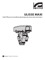
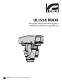
ULISSE MAXI
PTZ unit for dynamic monitoring of large outdoor areas


EN
English - Instructions manual
ENGLISH
ULISSE MAXI
PTZ unit for dynamic monitoring of large outdoor areas


Instructions manual - English - EN
3MNVCUPTMAXB_1511_EN
Contents
ENGLISH 1
1 About this manual ......................................................................................................... 7
1.1 Typographical conventions .................................................................................................................................. 7
2 Notes on copyright and information on trademarks .................................................. 7
3 Safety rules..................................................................................................................... 7
4 Identication ................................................................................................................10
4.1 Product description and type designation...................................................................................................10
4.2 Product markings ..................................................................................................................................................10
4.2.1 Checking the markings .......................................................................................................................................................10
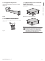
5 Versions ........................................................................................................................ 11
5.1 LED illuminators .....................................................................................................................................................11
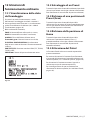
5.2 Germanium window .............................................................................................................................................11
6 Preparing the product for use .................................................................................... 12
6.1 Safety precautions before use ...........................................................................................................................12
6.2 Unpacking ................................................................................................................................................................ 12
6.3 Contents .................................................................................................................................................................... 12
6.4 Safely disposing of packaging material .........................................................................................................12
6.5 Preparatory work before installation .............................................................................................................. 13
6.5.1 Attaching the bracket ..........................................................................................................................................................13
6.5.2 Cables management ............................................................................................................................................................13
7 Assembly ...................................................................................................................... 14
7.1 Fixing the sunshield .............................................................................................................................................. 14
7.2 How to open the housing ................................................................................................................................... 14
7.3 Assembling the camera and motorised lenses ........................................................................................... 14
7.3.1 Cameras features ...................................................................................................................................................................14
7.3.2 Fastening the lens and the camera to the internal slide .........................................................................................15
7.3.3 Positioning of the H-20 spacer on the inner slide ......................................................................................................16
7.3.4 Internal slide ............................................................................................................................................................................ 16
7.4 Housing board description ................................................................................................................................17
7.4.1 Connection of the camera and motorised lens ..........................................................................................................17
7.4.2 Adjustment of the supply voltage of the lens motors .............................................................................................18
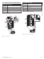
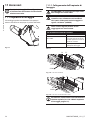
8 Installation ................................................................................................................... 19
8.1 Connecting the cables to the base ..................................................................................................................19
8.2 Fixing the base to the support ..........................................................................................................................20
8.3 Connector board description ............................................................................................................................ 21
8.4 Connection of the power supply line ............................................................................................................. 22
8.4.1 24Vac power line connection ............................................................................................................................................23
8.4.2 120Vac and 230Vac power line connection ................................................................................................................. 23
8.5 Signal cable connection ...................................................................................................................................... 24
8.5.1 Video cable connection ....................................................................................................................................................... 24
8.5.2 Telemetry lines connections .............................................................................................................................................. 25
8.5.3 Connection of the alarm inputs, of the twilight switch and of the relays .........................................................26

EN - English - Instructions manual
4 MNVCUPTMAXB_1511_EN
8.6 Fixing the upper body ..........................................................................................................................................27
8.7 Counterweights installation ..............................................................................................................................27
8.8 LED illuminators installation .............................................................................................................................. 28
8.8.1 Counterweight removal ......................................................................................................................................................28
8.8.2 Fitting the illuminator on the bracket ............................................................................................................................ 28
8.9 Connection of the LED illuminators ................................................................................................................ 29
8.10 Connection for cameras and LED illuminators synchronisation ........................................................30
8.11 Desiccant bag .......................................................................................................................................................30
8.12 LED illuminator activation and adjustment instructions ...................................................................... 30
8.12.1 Description of the LED illuminator ...............................................................................................................................30
8.12.2 Activation of the LED illuminator via an external dusk switch ...........................................................................31
8.12.3 Activation of the LED illuminator via the integrated dusk sensor ..................................................................... 31
8.12.4 LED illuminator switching on threshold adjustment .............................................................................................32
8.12.5 LED illuminator power adjustment ..............................................................................................................................32
8.13 Fastening of the wiper blade ..........................................................................................................................33
8.14 Hardware conguration ....................................................................................................................................34
8.14.1 Opening the conguration door ...................................................................................................................................34
8.14.2 DIP1 conguration ..............................................................................................................................................................34
8.14.3 DIP2 conguration ..............................................................................................................................................................34
8.14.4 DIP3 conguration ..............................................................................................................................................................35
8.14.4.1 Address conguration ............................................................................................................................................................................35
8.14.4.2 Setting of the serial communication lines ......................................................................................................................................35
8.14.5 DIP4 conguration ..............................................................................................................................................................35
8.14.6 Installation examples ......................................................................................................................................................... 36
8.14.6.1 RS-485 RX line ............................................................................................................................................................................................ 36
8.14.6.2 RS-422 line (RS-485-1 RX e RS-485-2 TX) ..........................................................................................................................................36
8.14.6.3 Line RS-485-1 reception, line RS-485-2 repetition........................................................................................................................36
8.14.6.4 Two-way RS-485 TX/RX line ..................................................................................................................................................................36
9 Switching on ................................................................................................................37
9.1 First start-up.............................................................................................................................................................37
9.2 Checks list ................................................................................................................................................................. 37
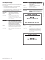
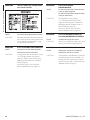
10 Conguration ............................................................................................................. 38
10.1 OSM interface (On Screen Menu) .................................................................................................................. 38
10.1.1 Using the OSM .....................................................................................................................................................................38
10.1.1.1 How to use the joystick ..........................................................................................................................................................................38
10.1.1.2 How to move around the menus........................................................................................................................................................39
10.1.1.3 How to modify the parameters ...........................................................................................................................................................39
10.1.1.4 How to change the numeric elds ..................................................................................................................................................... 40
10.1.1.5 How to change text .................................................................................................................................................................................40
10.1.2 Conguration via OSM ......................................................................................................................................................42
10.1.3 Main Menu .............................................................................................................................................................................42
10.1.4 Language Selection Menu ............................................................................................................................................... 42
10.1.5 ZFI Parameter Menu ........................................................................................................................................................... 42
10.1.5.1 Zone Titling Menu .................................................................................................................................................................................... 43
10.1.5.2 Zone Masking Menu ...............................................................................................................................................................................44
10.1.6 Housing Serial Port Menu ................................................................................................................................................45
10.1.7 Polarity Menu .......................................................................................................................................................................45
10.1.8 Movement Menu ................................................................................................................................................................. 46
10.1.8.1 Manual Control Menu ............................................................................................................................................................................. 46

Instructions manual - English - EN
5MNVCUPTMAXB_1511_EN
10.1.8.2 Manual Control Menu (Limits) ............................................................................................................................................................. 47
10.1.8.3 Preset Menu ...............................................................................................................................................................................................47
10.1.8.4 Preset Menu (Edit Preset) ......................................................................................................................................................................47
10.1.8.5 Preset Menu (Utility Preset) ..................................................................................................................................................................48
10.1.8.6 Patrol Menu ................................................................................................................................................................................................48
10.1.8.7 Autopan Menu ..........................................................................................................................................................................................48
10.1.8.8 Motion Recall Menu ................................................................................................................................................................................49
10.1.9 Display Menu ........................................................................................................................................................................ 49
10.1.10 Digital I/O-Options Menu .............................................................................................................................................. 49
10.1.10.1 Alarms Menu ...........................................................................................................................................................................................50
10.1.10.2 Communication menu ......................................................................................................................................................................... 50
10.1.10.3 Washer Menu ...........................................................................................................................................................................................51
10.1.11 Default Menu .....................................................................................................................................................................51
10.1.12 Info Menu ............................................................................................................................................................................51
11 Accessories ................................................................................................................. 52
11.1 Washer ..................................................................................................................................................................... 52
11.1.1 Washing system connection ...........................................................................................................................................52
11.2 Wall mount bracket ............................................................................................................................................53
11.3 Parapet bracket .................................................................................................................................................... 53
11.4 Power supply with illuminator control ........................................................................................................ 53
12 Instructions for normal operation ........................................................................... 54
12.1 Visualizing the state of the pan & tilt ............................................................................................................54
12.2 Saving a Preset .....................................................................................................................................................54
12.3 Restore a Preset position (Scan) .....................................................................................................................54
12.4 Recalling the Home position ...........................................................................................................................54
12.5 Patrol enabling ..................................................................................................................................................... 54
12.6 Autopan enabling ...............................................................................................................................................55
12.7 Enabling the wiper (Wiper) ..............................................................................................................................55
12.8 Enabling the washer (Washer) ........................................................................................................................55
12.9 Enabling the LED illuminator ..........................................................................................................................55
12.10 Unit Reboot .........................................................................................................................................................55
12.11 Special controls .................................................................................................................................................56
12.12 Special congurations.....................................................................................................................................57
13 Maintenance ..............................................................................................................58
13.1 Fuses replacement ..............................................................................................................................................58
14 Cleaning ..................................................................................................................... 58
14.1 Window and plastic cover cleaning .............................................................................................................. 58
14.2 Cleaning the germanium window ................................................................................................................ 58
15 Disposal of waste materials ......................................................................................58
16 Troubleshooting ........................................................................................................ 59
17 Technical data ............................................................................................................ 61
17.1 General .................................................................................................................................................................... 61
17.2 Mechanical .............................................................................................................................................................61
17.3 Housing's window...............................................................................................................................................61
17.4 Electrical .................................................................................................................................................................61

EN - English - Instructions manual
6 MNVCUPTMAXB_1511_EN
17.5 Video ........................................................................................................................................................................62
17.6 Communications .................................................................................................................................................62
17.7 Protocols ................................................................................................................................................................. 62
17.8 I/O interface ...........................................................................................................................................................62
17.9 Lenses ...................................................................................................................................................................... 62
17.10 Environment ....................................................................................................................................................... 62
17.11 Certications ......................................................................................................................................................62
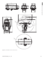
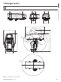
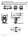
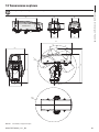
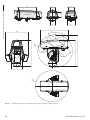
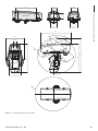
18 Technical drawings .................................................................................................... 63
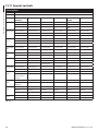
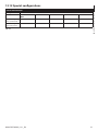
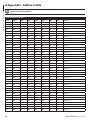
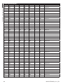
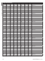
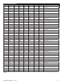
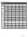
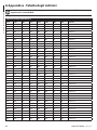
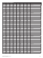
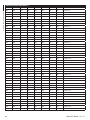
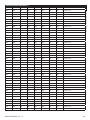
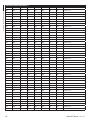
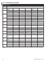
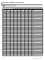
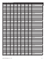
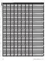
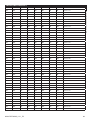
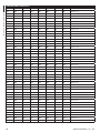
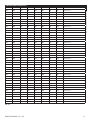
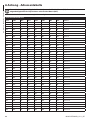
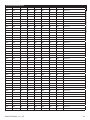
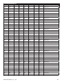
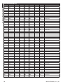
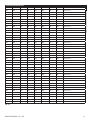
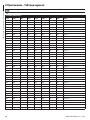
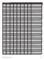
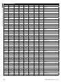
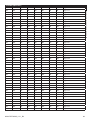
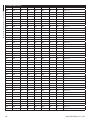
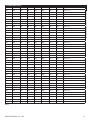
A Appendix - Address table ........................................................................................... 66

Instructions manual - English - EN
7MNVCUPTMAXB_1511_EN
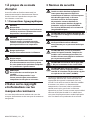
1 About this manual
Read all the documentation supplied carefully before
installing and using this unit. Keep the manual in a
convenient place for future reference.
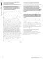
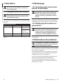
1.1 Typographical conventions
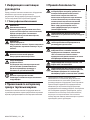
DANGER!
High level hazard.
Risk of electric shock. Disconnect the
power supply before proceeding with any
operation, unless indicated otherwise.
DANGER!
Hot surface.
Avoid contact. Surfaces are hot and may
cause personal injury if touched.
DANGER!
Mechanical hazard.
Risk of crushing or shearing.
CAUTION!
Medium level hazard.
This operation is very important for the
system to function properly. Please read
the procedure described very carefully and
carry it out as instructed.
INFO
Description of system specications.
We recommend reading this part carefully
in order to understand the subsequent
stages.
2 Notes on copyright and
information on trademarks
The quoted names of products or companies are
trademarks or registered trademarks.
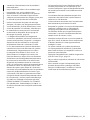
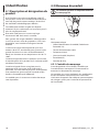
3 Safety rules
CAUTION! The electrical system to which
the unit is connected must be equipped
with a 20A max automatic bipolar circuit
breaker. This circuit breaker must be of
the Listed type. The minimum distance
between the circuit breaker contacts must
be 3mm (0.1in). The circuit breaker must be
provided with protection against the fault
current towards the ground (dierential)
and the overcurrent (magnetothermal).
CAUTION! Hazardous moving parts. Keep
ngers and other body parts away.
CAUTION! Device installation and
maintaining must be performed by
specialist technical sta only.
CAUTION! For continued protection against
risk of re, replace only with same type and
rating of fuse. Fuses must be replaced only
by service personnel.
CAUTION! TNV-1 installation type. The
installation is type TNV-1, do not connect it
to SELV circuits.
CAUTION! In order to reduce the risk of re,
only use UL Listed or CSA certied cables
with sections greater than or equal to
0.14mm² (26AWG).
• The manufacturer declines all responsibility
for any damage caused by an improper use
of the appliances mentioned in this manual.
Furthermore, the manufacturer reserves the right
to modify its contents without any prior notice.
The documentation contained in this manual has
been collected with great care. The manufacturer,
however, cannot take any liability for its use. The
same thing can be said for any person or company
involved in the creation and production of this
manual.

EN - English - Instructions manual
8 MNVCUPTMAXB_1511_EN
• Before starting any operation, make sure the
power supply is disconnected.
• Be careful not to use cables that seem worn or old.
• Never, under any circumstances, make any
changes or connections that are not shown in
this handbook. Improper use of the appliance
can cause serious hazards, risking the safety of
personnel and of the installation.
• Use only original spare parts. Non-original spare
parts could cause re, electrical discharge or other
hazards.
• Before proceeding with installation, check the
supplied material to make sure it corresponds
to the order specication by examining the
identication labels (4.2 Product markings, page
10).
• Installation category (also called Overvoltage
Category) species the level of mains voltage
surges that the equipment will be subjected to.
The category depends upon the location of the
equipment, and on any external surge protection
provided. Equipment in an industrial environment,
directly connected to major feeders/short branch
circuits, is subjected to Installation Category III. If
this is the case, a reduction to Installation Category
II is required. This can be achieved by use of an
insulating transformer with an earthed screen
between primary and secondary, or by tting UL
listed Surge Protective Devices (SPDs) from live
to neutral and from neutral to earth. Listed SPDs
shall be designed for repeated limiting of transient
voltage surges, suitable rated for operating voltage
and designated as follows: Type 2 (Permanently
connected SPDs intended for installation on the
load side of the service equipment overcurrent
device); Nominal Discharge Current (In) 20kA min.
For example: FERRAZ SHAWMUT, STT2240SPG-
CN, STT2BL240SPG-CN rated 120Vac/240Vac,
(In=20kA). Maximum distance between installation
and reduction is 5m.
• This device was designed to be permanently
secured and connected on a building or on a
suitable structure. The device must be permanently
secured and connected before any operation.
• A power disconnect device must be included
in the electrical installation, and it must be very
quickly recognizable and operated if needed.
• The separate protective earthing terminal provided
on this product shall be permanently connected
to earth.
• Connect the device to a power source
corresponding to the indications given on the
marking label. Before proceeding with installation
make sure that the power line is properly isolated.
The supply voltage should never exceed the limit
(±10%).
• Power supply must be provided with a SELV type,
24Vac, 8A isolated source derived from a double
isolation UL Listed transformer specially protected
in output.
• The device should be mounted so that it is
accessible only to the technician/installer because
the moving parts constitute a residual risk of injury
caused by movement of said parts.
• Attach the Dangerous Moving Parts label near the
device. (Fig. 4, page12).
• Do not use the appliance in the presence of
inammable substances.
• To connect the power supply line use the
appropriate junction-box (UPTJBUL). For further
information, refer to the product use and
installation manual.

Instructions manual - English - EN
9MNVCUPTMAXB_1511_EN
• Do not allow children or unauthorised people to
use the appliance.
• Only skilled personnel should carry out
maintenance on the device. When carrying out
maintenance, the operator is exposed to the risk of
electrocution and other hazards.
• Use only the accessories indicated by the
manufacturer. Any change that is not expressly
approved by the manufacturer will invalidate the
guarantee.
• Connect the coaxial cable to earth.
• Before connecting all the cables make sure the
device is properly connected to the earth circuit.
• If the device has to be removed from the
installation, always disconnect the earth cable last.
• Take all necessary precautions to prevent the
apparatus from being damaged by electrostatic
discharge.
• The unit has been made for connection using a
3-pole cable. To make a correct connection to
the earth circuit, follow the instructions in this
handbook.
• Handle the unit with great care, high mechanical
stress could damage it.
• Make especially sure that the power supply line is
insulated at a sucient distance from all the other
cables, including lightning protection devices.
• If it is necessary to transport the device, this should
be done with great care. Abrupt stops, bumps and
violent impact could damage the unit or injure the
user.

EN - English - Instructions manual
10 MNVCUPTMAXB_1511_EN
4 Identication
4.1 Product description and type
designation
ULISSE MAXI is a robust and ecient PTZ camera
unit designed to ensure dynamic and non-stop
surveillance of large outdoor areas and withstand
harsh weather conditions.
This model can contain and manage the largest
motorised lenses on the market, with a total weight
of up to almost 8 kilos.
This way a single unit can provide a 360° coverage of
the area to be monitored.
To ensure detailed images even during the night
hours, versions are available with LED illuminators,
with infrared light or white light.
The sturdy mechanical structure and the powerful
motors of this PTZ are designed to guarantee
maximum resistance to high operating stress,
vibrations and temperatures between -10°C to +60°C.
The unit is equipped with optical sensors which
ensure the accurate control of the position in any
condition of use.
The unit is equipped with a wiper for removing
rain and dust from the front glass; there is a wide
selection of jerry cans with washer pump, dierent
capacities and heads.
Models are available for vision with a thermal camera.
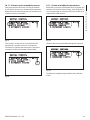
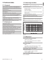
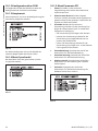
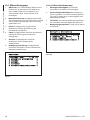
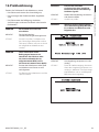
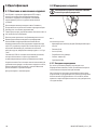
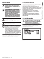
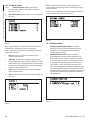
4.2 Product markings
Pan & tilt devices have a label complying
with CE markings.
Fig. 1
The label shows:
• Model identication code (Extended 3/9 bar code).
• Power supply (Volt).
• Frequency (Hertz).
• Current consumption (Amps).
• Weatherproof standard (IP).
• Serial number.
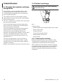
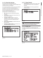
4.2.1 Checking the markings
Before proceeding further with installation, make
sure the material supplied corresponds to the order
specication by examining the marking labels.
Never, under any circumstances, make any changes
or connections that are not shown in this handbook.
Improper use of the appliance can cause serious
hazards, risking the safety of personnel and of the
installation.

Instructions manual - English - EN
11MNVCUPTMAXB_1511_EN
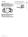
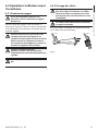
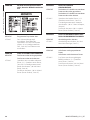
5 Versions
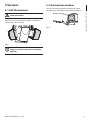
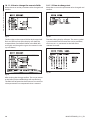
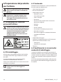
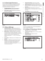
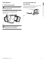
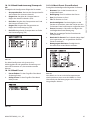
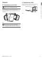
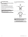
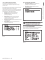
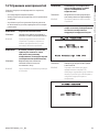
5.1 LED illuminators
The version with LED illuminators can only
powered at 24Vac.
The pan & tilt can be tted with bracket for 2
VIDEOTEC LED illuminators for night surveillance
(illuminators not included).
Fig. 2
For further information refer to the relative
chapter (8.8 LED illuminators installation,
page28).
5.2 Germanium window
The version with germanium window has been
developed for applications with thermal cameras.
Fig. 3

EN - English - Instructions manual
12 MNVCUPTMAXB_1511_EN
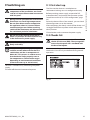
6 Preparing the product for
use
Any change that is not expressly approved
by the manufacturer will invalidate the
guarantee.
The unit must not be dismantled or
tampered with. The only exceptions
are those concerning the assembly and
maintenance operations stipulated in this
manual.
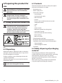
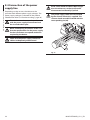
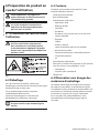
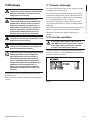
6.1 Safety precautions before use
The appliance includes moving parts. Make
sure that the unit is positioned where it
is inaccessible under normal operating
conditions. Attach the warning label
supplied with the appliance, placing it near
the unit so that it can be seen easily.
Fig. 4
6.2 Unpacking
When the product is delivered, make sure that the
package is intact and that there are no signs that it
has been dropped or scratched.
If there are obvious signs of damage, contact the
supplier immediately.
Keep the packaging in case you need to send the
product for repairs.
Unpack the sunshield of the device, taking
care not to damage the housing.
6.3 Contents
Check the contents to make sure they correspond
with the list of materials as below:
• Positioning unit
• Power supply base
• Accessories package:
• Serial adapter
• Serial extension cable
• Allen wrenches
• Spacers
• Spacers (not available in the version with
integrated camera)
• Label
• Ties
• Silicon sheath
• Reduction gaskets for cable glands
• Instructions manual
• Attachment plate for desiccant bag
• Desiccant bag
• Bolts and screws
• Counterweights package:
• Bracket for attachment of LED illuminators
(available in the versions with LED illuminators)
• Counterweights
• Counterweights brackets
• Sunshield
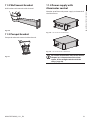
6.4 Safely disposing of packaging
material
The packaging material can all be recycled. The
installer technician will be responsible for separating
the material for disposal, and in any case for
compliance with the legislation in force where the
device is to be used.
When returning a faulty product we recommend
using the original packaging for shipping.

Instructions manual - English - EN
13MNVCUPTMAXB_1511_EN
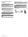
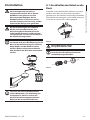
6.5 Preparatory work before
installation
6.5.1 Attaching the bracket
For installations subject to vibrations, only
use the parapet bracket.
Dierent types of supports are available (11
Accessories, page52). Choose a suitable bracket for
the installation and follow all the instructions in the
suggested chapter.
Take special care when attaching and
fastening down the apparatus. The
clamping system must be able to support
at least 4 times the weight of the entire
equipment, including P&T, lenses and
camera.
The device should be assembled vertically.
Any other position could impair the
performance of the appliance.
Do not attach the device upside down.
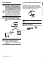
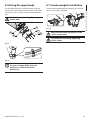
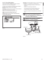
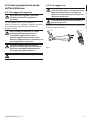
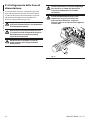
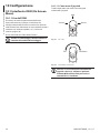
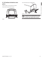
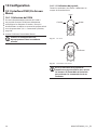
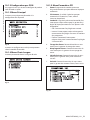
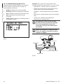
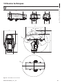
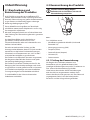
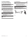
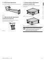
6.5.2 Cables management
The connection cables should not be
accessible from the outside. It is necessary
to fasten the cables securely to the support
in order to prevent excessive weight pulling
them out accidentaly.
You must use cables suited to the type of
installation.
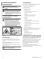
Insert the cables into the support so that they
protrude by about 50cm.
50cm50cm
Fig. 5

EN - English - Instructions manual
14 MNVCUPTMAXB_1511_EN
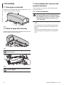
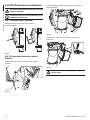
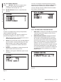
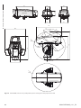
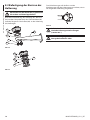
7 Assembly
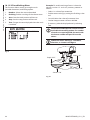
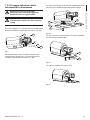
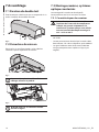
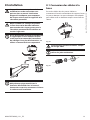
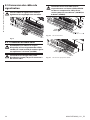
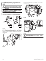
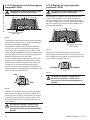
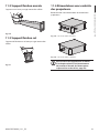
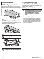
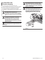
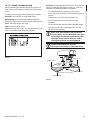
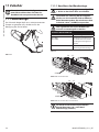
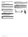
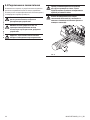
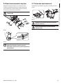
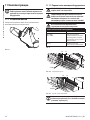
7.1 Fixing the sunshield
Mount the sunshield to the housing with the 4 screws
and 4 washers couples provided.
Fig. 6
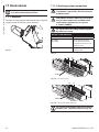
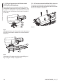
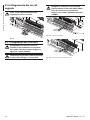
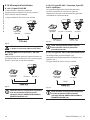
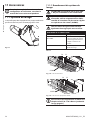
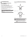
7.2 How to open the housing
Loosen the leak-proof screws placed on the sides and
lift the upper part of the housing.
Fig. 7
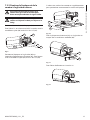
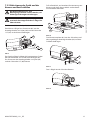
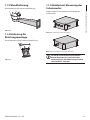
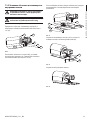
After installation and wiring, close the
product again.
Fig. 8
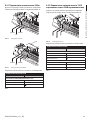
First of all tighten the two central screws as
shown in gure.
7.3 Assembling the camera and
motorised lenses
The customer has to take care of assembling the
camera and lenses.
7.3.1 Cameras features
The correct operation of the equipment,
within the temperature range indicated, is
guaranteed only if you use camera and lens
with temperature limits equal to at least
-10°C and +60°C.
• The power supply voltage of the camera must be
12Vdc.
• The maximum current absorbed by the camera
must be lower than the value indicated below:
800mA.
• The camera output video signal must be of the
composite type with amplitude 1Vpp (negative
sync).

Instructions manual - English - EN
15MNVCUPTMAXB_1511_EN
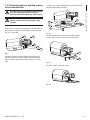
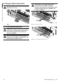
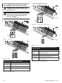
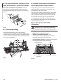
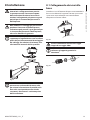
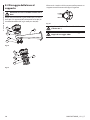
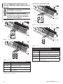
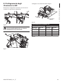
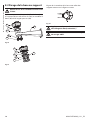
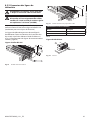
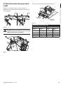
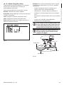
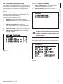
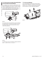
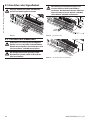
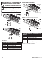
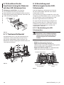
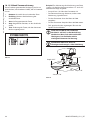
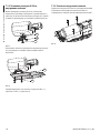
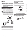
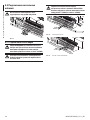
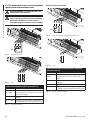
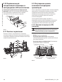
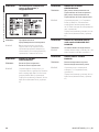
7.3.2 Fastening the lens and the camera
to the internal slide
It is necessary to insulate the camera body
from the attachment slide in order to
prevent interference with the video signal.
Maximum overall weight allowed for
camera and lens must not exceed 7.6kg
(16.8lb).
Connect the camera (02) to the lens (01).
Fasten the L-shaped small aluminium bracket (03) to
the camera by means of the nylon washer (04) and
the 1/4" screw (05).
01 02
03
04
05
Fig. 9
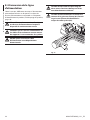
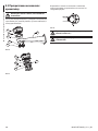
Position the lens on the slide (02) interposing the
plastic spacer (01). Fasten the whole assembly by
means of the nylon washer (03)and the 1/4" screw
(04).
If necessary, use the additional spacers to correctly
position the camera and lens.
01
02
03
04
Fig. 10
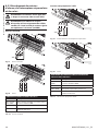
Fasten the aluminium plate (01) on the slide by
means of the screws and relative washers (02).
02
01
Fig. 11
Fix the L-bracket with the screw.
Fig. 12

EN - English - Instructions manual
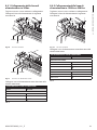
16 MNVCUPTMAXB_1511_EN
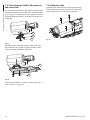
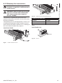
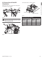
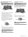
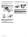
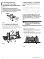
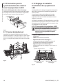
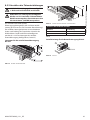
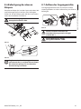
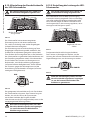
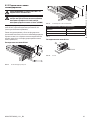
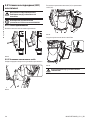
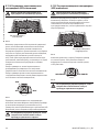
7.3.3 Positioning of the H-20 spacer on
the inner slide
It is possible to fasten the H-20 spacer (02) to the lens.
Connect the camera and fasten the L-shaped bracket
(Fig. 9, page15). Interpose a plastic spacer (01) of the
required thicknessand x it by means of washer and
screw (03).
01
02
03
Fig. 13
Position the lens with the spacer on the inner slide
(01) and fasten the spacer by means of the washers
and screws (02) provided as standard.
01
02
Fig. 14
Finish the installation as shown in the images (Fig. 11,
page15 e Fig. 12, page15).
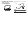
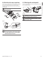
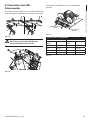
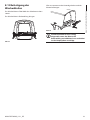
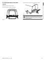
7.3.4 Internal slide
Shift the inner slide with lens and camera already
fastened into the wanted position and secure it by
means of the washers and screws provided.
Fig. 15

Instructions manual - English - EN
17MNVCUPTMAXB_1511_EN
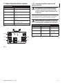
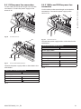
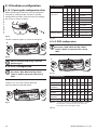
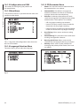
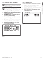
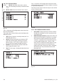
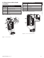
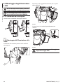
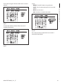
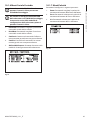
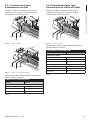
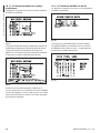
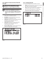
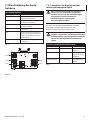
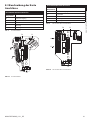
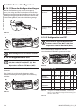
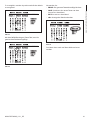
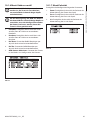
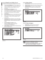
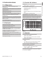
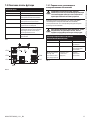
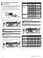
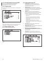
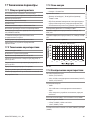
7.4 Housing board description
BOARD DESCRIPTION
Connector/Terminal Function
CN1 BNC connector, video signal from the
camera
CN2 Motorised lens motor control
connector
CN3 Motorised lens potentiometer
connector
CN6 Serial connector for controlling the
camera
CN7 Camera power supply, dry contact
for activating the Day/Night camera
mode, additional lines
DIP1 Select the lens power supply voltage
Tab. 1
CN6
CN3
CN2
CN1
CN7
DIP1
Fig. 16
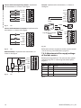
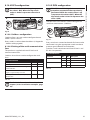
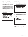
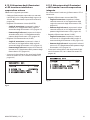
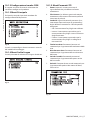
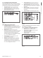
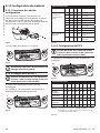
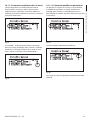
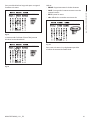
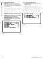
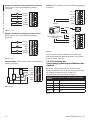
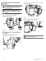
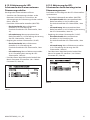
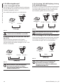
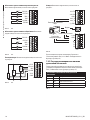
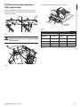
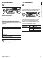
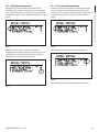
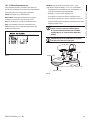
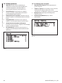
7.4.1 Connection of the camera and
motorised lens
All connections illustrated below should
be made only and exclusively by expert
installers who should comply with all the
wiring and power supply specications for
the devices.
The electronics board is designed to control cameras
with motorised lenses, which may or may not have
potentiometers to control the position reached.
Before making the connections make sure
that the voltages supplied by the board fall
within the limits allowed for the apparatus.
CONNECTOR FOR CAMERA/MOTORISED LENSES
Voltage Current Description
+12V 800mA max Camera power
supply
+5V 15mA max Lens potentiometer
power supply
From 6Vdc up to
15Vdc (adjustable)
200mA max
(Focus+Zoom+Iris)
Lens motor power
supply
Tab. 2

EN - English - Instructions manual
18 MNVCUPTMAXB_1511_EN
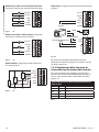
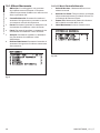
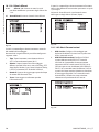
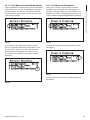
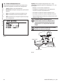
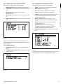
Lenses with reverse polarity motors: Implement
the connections, as shown in the gure..
FOCUS +
FOCUS -
IRIS +
IRIS -
ZOOM +
ZOOM -
+
M
+
M
+
M
CN2
Fig. 17 CN2.
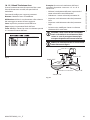
Lenses with common wire motors: Implement the
connections, as shown in the gure..
FOCUS +
FOCUS -
IRIS +
IRIS -
ZOOM +
ZOOM -
+
M
+
M
+
M
CN2
Fig. 18 CN2.
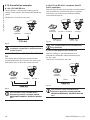
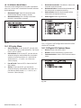
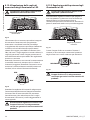
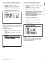
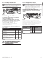
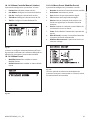
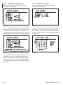
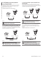
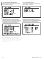
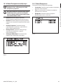
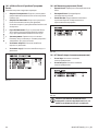
Potentiometers: Implement the connections, as
shown in the gure..
+ POT
FOCUS
IRIS
ZOOM
- POT
GND
CN3
IRIS
ZOOM
FOCUS
Fig. 19 CN3.
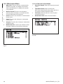
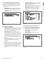
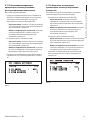
Camera: Implement the connections, as shown in
the gure..
CN6
232 TX
232 RX
GND
485_B
485_A
S_GND
+ 12V
GND
F1
F2
CN1
Serial
Day/Night synchroni-
sation
Power supply
Video
Fig. 20
Refer to the relative chapter to enable camera control
(10.1.6 Housing Serial Port Menu, page45).
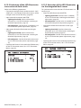
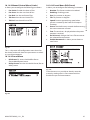
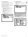
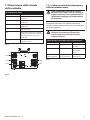
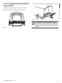
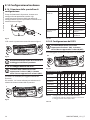
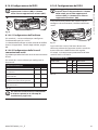
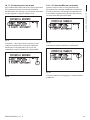
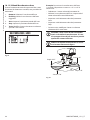
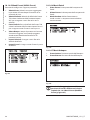
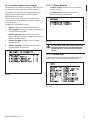
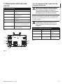
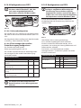
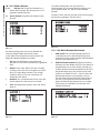
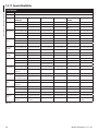
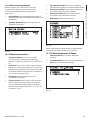
7.4.2 Adjustment of the supply voltage
of the lens motors
Before powering the Pan & Tilt, select the lens power
voltage using DIP1 (7.4 Housing board description,
page17).
ADJUSTMENT OF THE SUPPLY VOLTAGE OF THE LENS MOTORS
SW1 SW2 Voltage
OFF OFF 15Vdc
ON OFF 12Vdc
OFF ON 9Vdc
ON ON 6Vdc
Tab. 3
La pagina si sta caricando...
La pagina si sta caricando...
La pagina si sta caricando...
La pagina si sta caricando...
La pagina si sta caricando...
La pagina si sta caricando...
La pagina si sta caricando...
La pagina si sta caricando...
La pagina si sta caricando...
La pagina si sta caricando...
La pagina si sta caricando...
La pagina si sta caricando...
La pagina si sta caricando...
La pagina si sta caricando...
La pagina si sta caricando...
La pagina si sta caricando...
La pagina si sta caricando...
La pagina si sta caricando...
La pagina si sta caricando...
La pagina si sta caricando...
La pagina si sta caricando...
La pagina si sta caricando...
La pagina si sta caricando...
La pagina si sta caricando...
La pagina si sta caricando...
La pagina si sta caricando...
La pagina si sta caricando...
La pagina si sta caricando...
La pagina si sta caricando...
La pagina si sta caricando...
La pagina si sta caricando...
La pagina si sta caricando...
La pagina si sta caricando...
La pagina si sta caricando...
La pagina si sta caricando...
La pagina si sta caricando...
La pagina si sta caricando...
La pagina si sta caricando...
La pagina si sta caricando...
La pagina si sta caricando...
La pagina si sta caricando...
La pagina si sta caricando...
La pagina si sta caricando...
La pagina si sta caricando...
La pagina si sta caricando...
La pagina si sta caricando...
La pagina si sta caricando...
La pagina si sta caricando...
La pagina si sta caricando...
La pagina si sta caricando...
La pagina si sta caricando...
La pagina si sta caricando...
La pagina si sta caricando...
La pagina si sta caricando...
La pagina si sta caricando...
La pagina si sta caricando...
La pagina si sta caricando...
La pagina si sta caricando...
La pagina si sta caricando...
La pagina si sta caricando...
La pagina si sta caricando...
La pagina si sta caricando...
La pagina si sta caricando...
La pagina si sta caricando...
La pagina si sta caricando...
La pagina si sta caricando...
La pagina si sta caricando...
La pagina si sta caricando...
La pagina si sta caricando...
La pagina si sta caricando...
La pagina si sta caricando...
La pagina si sta caricando...
La pagina si sta caricando...
La pagina si sta caricando...
La pagina si sta caricando...
La pagina si sta caricando...
La pagina si sta caricando...
La pagina si sta caricando...
La pagina si sta caricando...
La pagina si sta caricando...
La pagina si sta caricando...
La pagina si sta caricando...
La pagina si sta caricando...
La pagina si sta caricando...
La pagina si sta caricando...
La pagina si sta caricando...
La pagina si sta caricando...
La pagina si sta caricando...
La pagina si sta caricando...
La pagina si sta caricando...
La pagina si sta caricando...
La pagina si sta caricando...
La pagina si sta caricando...
La pagina si sta caricando...
La pagina si sta caricando...
La pagina si sta caricando...
La pagina si sta caricando...
La pagina si sta caricando...
La pagina si sta caricando...
La pagina si sta caricando...
La pagina si sta caricando...
La pagina si sta caricando...
La pagina si sta caricando...
La pagina si sta caricando...
La pagina si sta caricando...
La pagina si sta caricando...
La pagina si sta caricando...
La pagina si sta caricando...
La pagina si sta caricando...
La pagina si sta caricando...
La pagina si sta caricando...
La pagina si sta caricando...
La pagina si sta caricando...
La pagina si sta caricando...
La pagina si sta caricando...
La pagina si sta caricando...
La pagina si sta caricando...
La pagina si sta caricando...
La pagina si sta caricando...
La pagina si sta caricando...
La pagina si sta caricando...
La pagina si sta caricando...
La pagina si sta caricando...
La pagina si sta caricando...
La pagina si sta caricando...
La pagina si sta caricando...
La pagina si sta caricando...
La pagina si sta caricando...
La pagina si sta caricando...
La pagina si sta caricando...
La pagina si sta caricando...
La pagina si sta caricando...
La pagina si sta caricando...
La pagina si sta caricando...
La pagina si sta caricando...
La pagina si sta caricando...
La pagina si sta caricando...
La pagina si sta caricando...
La pagina si sta caricando...
La pagina si sta caricando...
La pagina si sta caricando...
La pagina si sta caricando...
La pagina si sta caricando...
La pagina si sta caricando...
La pagina si sta caricando...
La pagina si sta caricando...
La pagina si sta caricando...
La pagina si sta caricando...
La pagina si sta caricando...
La pagina si sta caricando...
La pagina si sta caricando...
La pagina si sta caricando...
La pagina si sta caricando...
La pagina si sta caricando...
La pagina si sta caricando...
La pagina si sta caricando...
La pagina si sta caricando...
La pagina si sta caricando...
La pagina si sta caricando...
La pagina si sta caricando...
La pagina si sta caricando...
La pagina si sta caricando...
La pagina si sta caricando...
La pagina si sta caricando...
La pagina si sta caricando...
La pagina si sta caricando...
La pagina si sta caricando...
La pagina si sta caricando...
La pagina si sta caricando...
La pagina si sta caricando...
La pagina si sta caricando...
La pagina si sta caricando...
La pagina si sta caricando...
La pagina si sta caricando...
La pagina si sta caricando...
La pagina si sta caricando...
La pagina si sta caricando...
La pagina si sta caricando...
La pagina si sta caricando...
La pagina si sta caricando...
La pagina si sta caricando...
La pagina si sta caricando...
La pagina si sta caricando...
La pagina si sta caricando...
La pagina si sta caricando...
La pagina si sta caricando...
La pagina si sta caricando...
La pagina si sta caricando...
La pagina si sta caricando...
La pagina si sta caricando...
La pagina si sta caricando...
La pagina si sta caricando...
La pagina si sta caricando...
La pagina si sta caricando...
La pagina si sta caricando...
La pagina si sta caricando...
La pagina si sta caricando...
La pagina si sta caricando...
La pagina si sta caricando...
La pagina si sta caricando...
La pagina si sta caricando...
La pagina si sta caricando...
La pagina si sta caricando...
La pagina si sta caricando...
La pagina si sta caricando...
La pagina si sta caricando...
La pagina si sta caricando...
La pagina si sta caricando...
La pagina si sta caricando...
La pagina si sta caricando...
La pagina si sta caricando...
La pagina si sta caricando...
La pagina si sta caricando...
La pagina si sta caricando...
La pagina si sta caricando...
La pagina si sta caricando...
La pagina si sta caricando...
La pagina si sta caricando...
La pagina si sta caricando...
La pagina si sta caricando...
La pagina si sta caricando...
La pagina si sta caricando...
La pagina si sta caricando...
La pagina si sta caricando...
La pagina si sta caricando...
La pagina si sta caricando...
La pagina si sta caricando...
La pagina si sta caricando...
La pagina si sta caricando...
La pagina si sta caricando...
La pagina si sta caricando...
La pagina si sta caricando...
La pagina si sta caricando...
La pagina si sta caricando...
La pagina si sta caricando...
La pagina si sta caricando...
La pagina si sta caricando...
La pagina si sta caricando...
La pagina si sta caricando...
La pagina si sta caricando...
La pagina si sta caricando...
La pagina si sta caricando...
La pagina si sta caricando...
La pagina si sta caricando...
La pagina si sta caricando...
La pagina si sta caricando...
La pagina si sta caricando...
La pagina si sta caricando...
La pagina si sta caricando...
La pagina si sta caricando...
La pagina si sta caricando...
La pagina si sta caricando...
La pagina si sta caricando...
La pagina si sta caricando...
La pagina si sta caricando...
La pagina si sta caricando...
La pagina si sta caricando...
La pagina si sta caricando...
La pagina si sta caricando...
La pagina si sta caricando...
La pagina si sta caricando...
La pagina si sta caricando...
La pagina si sta caricando...
La pagina si sta caricando...
La pagina si sta caricando...
La pagina si sta caricando...
La pagina si sta caricando...
La pagina si sta caricando...
La pagina si sta caricando...
La pagina si sta caricando...
La pagina si sta caricando...
La pagina si sta caricando...
La pagina si sta caricando...
La pagina si sta caricando...
La pagina si sta caricando...
La pagina si sta caricando...
La pagina si sta caricando...
La pagina si sta caricando...
La pagina si sta caricando...
La pagina si sta caricando...
La pagina si sta caricando...
La pagina si sta caricando...
La pagina si sta caricando...
La pagina si sta caricando...
La pagina si sta caricando...
La pagina si sta caricando...
La pagina si sta caricando...
La pagina si sta caricando...
La pagina si sta caricando...
La pagina si sta caricando...
La pagina si sta caricando...
La pagina si sta caricando...
La pagina si sta caricando...
La pagina si sta caricando...
La pagina si sta caricando...
La pagina si sta caricando...
La pagina si sta caricando...
La pagina si sta caricando...
La pagina si sta caricando...
La pagina si sta caricando...
La pagina si sta caricando...
La pagina si sta caricando...
La pagina si sta caricando...
La pagina si sta caricando...
La pagina si sta caricando...
La pagina si sta caricando...
La pagina si sta caricando...
La pagina si sta caricando...
La pagina si sta caricando...
La pagina si sta caricando...
La pagina si sta caricando...
La pagina si sta caricando...
La pagina si sta caricando...
La pagina si sta caricando...
La pagina si sta caricando...
La pagina si sta caricando...
La pagina si sta caricando...
La pagina si sta caricando...
La pagina si sta caricando...
La pagina si sta caricando...
La pagina si sta caricando...
La pagina si sta caricando...
La pagina si sta caricando...
La pagina si sta caricando...
La pagina si sta caricando...
La pagina si sta caricando...
La pagina si sta caricando...
La pagina si sta caricando...
La pagina si sta caricando...
La pagina si sta caricando...
La pagina si sta caricando...
La pagina si sta caricando...
La pagina si sta caricando...
La pagina si sta caricando...
La pagina si sta caricando...
La pagina si sta caricando...
La pagina si sta caricando...
La pagina si sta caricando...
La pagina si sta caricando...
La pagina si sta caricando...
La pagina si sta caricando...
La pagina si sta caricando...
La pagina si sta caricando...
La pagina si sta caricando...
-
 1
1
-
 2
2
-
 3
3
-
 4
4
-
 5
5
-
 6
6
-
 7
7
-
 8
8
-
 9
9
-
 10
10
-
 11
11
-
 12
12
-
 13
13
-
 14
14
-
 15
15
-
 16
16
-
 17
17
-
 18
18
-
 19
19
-
 20
20
-
 21
21
-
 22
22
-
 23
23
-
 24
24
-
 25
25
-
 26
26
-
 27
27
-
 28
28
-
 29
29
-
 30
30
-
 31
31
-
 32
32
-
 33
33
-
 34
34
-
 35
35
-
 36
36
-
 37
37
-
 38
38
-
 39
39
-
 40
40
-
 41
41
-
 42
42
-
 43
43
-
 44
44
-
 45
45
-
 46
46
-
 47
47
-
 48
48
-
 49
49
-
 50
50
-
 51
51
-
 52
52
-
 53
53
-
 54
54
-
 55
55
-
 56
56
-
 57
57
-
 58
58
-
 59
59
-
 60
60
-
 61
61
-
 62
62
-
 63
63
-
 64
64
-
 65
65
-
 66
66
-
 67
67
-
 68
68
-
 69
69
-
 70
70
-
 71
71
-
 72
72
-
 73
73
-
 74
74
-
 75
75
-
 76
76
-
 77
77
-
 78
78
-
 79
79
-
 80
80
-
 81
81
-
 82
82
-
 83
83
-
 84
84
-
 85
85
-
 86
86
-
 87
87
-
 88
88
-
 89
89
-
 90
90
-
 91
91
-
 92
92
-
 93
93
-
 94
94
-
 95
95
-
 96
96
-
 97
97
-
 98
98
-
 99
99
-
 100
100
-
 101
101
-
 102
102
-
 103
103
-
 104
104
-
 105
105
-
 106
106
-
 107
107
-
 108
108
-
 109
109
-
 110
110
-
 111
111
-
 112
112
-
 113
113
-
 114
114
-
 115
115
-
 116
116
-
 117
117
-
 118
118
-
 119
119
-
 120
120
-
 121
121
-
 122
122
-
 123
123
-
 124
124
-
 125
125
-
 126
126
-
 127
127
-
 128
128
-
 129
129
-
 130
130
-
 131
131
-
 132
132
-
 133
133
-
 134
134
-
 135
135
-
 136
136
-
 137
137
-
 138
138
-
 139
139
-
 140
140
-
 141
141
-
 142
142
-
 143
143
-
 144
144
-
 145
145
-
 146
146
-
 147
147
-
 148
148
-
 149
149
-
 150
150
-
 151
151
-
 152
152
-
 153
153
-
 154
154
-
 155
155
-
 156
156
-
 157
157
-
 158
158
-
 159
159
-
 160
160
-
 161
161
-
 162
162
-
 163
163
-
 164
164
-
 165
165
-
 166
166
-
 167
167
-
 168
168
-
 169
169
-
 170
170
-
 171
171
-
 172
172
-
 173
173
-
 174
174
-
 175
175
-
 176
176
-
 177
177
-
 178
178
-
 179
179
-
 180
180
-
 181
181
-
 182
182
-
 183
183
-
 184
184
-
 185
185
-
 186
186
-
 187
187
-
 188
188
-
 189
189
-
 190
190
-
 191
191
-
 192
192
-
 193
193
-
 194
194
-
 195
195
-
 196
196
-
 197
197
-
 198
198
-
 199
199
-
 200
200
-
 201
201
-
 202
202
-
 203
203
-
 204
204
-
 205
205
-
 206
206
-
 207
207
-
 208
208
-
 209
209
-
 210
210
-
 211
211
-
 212
212
-
 213
213
-
 214
214
-
 215
215
-
 216
216
-
 217
217
-
 218
218
-
 219
219
-
 220
220
-
 221
221
-
 222
222
-
 223
223
-
 224
224
-
 225
225
-
 226
226
-
 227
227
-
 228
228
-
 229
229
-
 230
230
-
 231
231
-
 232
232
-
 233
233
-
 234
234
-
 235
235
-
 236
236
-
 237
237
-
 238
238
-
 239
239
-
 240
240
-
 241
241
-
 242
242
-
 243
243
-
 244
244
-
 245
245
-
 246
246
-
 247
247
-
 248
248
-
 249
249
-
 250
250
-
 251
251
-
 252
252
-
 253
253
-
 254
254
-
 255
255
-
 256
256
-
 257
257
-
 258
258
-
 259
259
-
 260
260
-
 261
261
-
 262
262
-
 263
263
-
 264
264
-
 265
265
-
 266
266
-
 267
267
-
 268
268
-
 269
269
-
 270
270
-
 271
271
-
 272
272
-
 273
273
-
 274
274
-
 275
275
-
 276
276
-
 277
277
-
 278
278
-
 279
279
-
 280
280
-
 281
281
-
 282
282
-
 283
283
-
 284
284
-
 285
285
-
 286
286
-
 287
287
-
 288
288
-
 289
289
-
 290
290
-
 291
291
-
 292
292
-
 293
293
-
 294
294
-
 295
295
-
 296
296
-
 297
297
-
 298
298
-
 299
299
-
 300
300
-
 301
301
-
 302
302
-
 303
303
-
 304
304
-
 305
305
-
 306
306
-
 307
307
-
 308
308
-
 309
309
-
 310
310
-
 311
311
-
 312
312
-
 313
313
-
 314
314
-
 315
315
-
 316
316
-
 317
317
-
 318
318
-
 319
319
-
 320
320
-
 321
321
-
 322
322
-
 323
323
-
 324
324
-
 325
325
-
 326
326
-
 327
327
-
 328
328
-
 329
329
-
 330
330
-
 331
331
-
 332
332
-
 333
333
-
 334
334
-
 335
335
-
 336
336
-
 337
337
-
 338
338
-
 339
339
-
 340
340
-
 341
341
-
 342
342
-
 343
343
-
 344
344
-
 345
345
-
 346
346
-
 347
347
-
 348
348
-
 349
349
-
 350
350
-
 351
351
-
 352
352
-
 353
353
-
 354
354
-
 355
355
-
 356
356
-
 357
357
-
 358
358
-
 359
359
-
 360
360
-
 361
361
-
 362
362
-
 363
363
-
 364
364


in altre lingue
- français: Videotec ULISSE MAXI Manuel utilisateur
Documenti correlati
-
Videotec ULISSE Manuale utente
-
Videotec ULISSE RADICAL Manuale utente
-
-
Videotec ULISSE2 Manuale utente
-
-
-
-
-
-
Altri documenti
-
Comelit AHPTZ120A Manuale utente
-
Axis Communications Q8721 Manuale utente
-
Axis Q8722-E Guida d'installazione
-
 nologo ZMINI-Z180 User And Installer Manual
-
Dedicated Micros DRX Series Telemetry Receivers Manuale del proprietario
-
Yukon Patrol NV monocular Manuale utente
-
Schneider Electric TM172DCLF. Display Color TouchScreen Flush Instruction Sheet
-
-
CAME TS4.3 Guida d'installazione
-
Invacare LiNX DLX-REM400 Manuale utente
