Viscount Hurricane 210 Manuale del proprietario
- Categoria
- Altoparlanti
- Tipo
- Manuale del proprietario

Ver. 1.1
Manuale Utente - IT
User Manual - EN


IT - 1
Manuale Utente
INDICE
1. Note importanti ..............................................................................................................................................1
1.1 Cura del prodotto .......................................................................................................................................... 1
1.2 Collegamenti .................................................................................................................................................. 1
1.3 Note riguardanti questo manuale .................................................................................................................. 1
2. Caratteristiche generali di Hurricane 210 ......................................................................................................2
3. Pannello di collegamento e controllo .............................................................................................................2
4. Esempio di collegamento ..............................................................................................................................3
5. Specifiche tecniche .......................................................................................................................................4
1. NOTE IMPORTANTI
1.1 CURA DEL PRODOTTO
Non applicate eccessiva forza alle strutture ed ai comandi del prodotto (pulsanti, interruttori, ecc…).
Non collocate, quando possibile, il prodotto in prossimità di unità che producano forti interferenze come
apparecchi radio – TV, monitor, ecc...
Evitate di posizionare il prodotto in prossimità di fonti di calore, in luoghi umidi o polverosi o nelle vicinanze
di forti campi magnetici.
Evitate di esporre il prodotto all’irradiazione solare diretta.
Non introdurre per nessuna ragione oggetti estranei o liquidi di qualsiasi genere all’interno del prodotto.
Per la pulizia usate solo un pennello morbido od aria compressa.
1.2 COLLEGAMENTI
Prima di effettuare i collegamenti accertatevi che tutte le casse che state utilizzando siano spente.
Eviterete rumorosi se non pericolosi picchi di segnale.
In caso di lunghi periodi di inutilizzo del prodotto scollegate la spina della presa di corrente.
Collegate il cavo di alimentazione ad una presa di corrente provvista di contatto di terra.
Accertatevi che la tensione di rete corrisponda a quella indicata sulla targhetta matricola dell’apparato.
Controllate periodicamente la pulizia della spina elettrica.
Utilizzate solo il cavo di alimentazione fornito in dotazione.
Non posizionare il cavo di alimentazione in prossimità di fonti di calore. Non piegarlo eccessivamente, né
danneggiarlo.
Non posizionare oggetti pesanti sul cavo, né collocarlo in luoghi dove potrebbe essere calpestato.
1.3 NOTE RIGUARDANTI QUESTO MANUALE
Conservate con cura questo manuale.
Il presente manuale costituisce parte integrante dello strumento. Le descrizioni e le illustrazioni contenute
nella presente pubblicazione si intendono non impegnative.
Ferme restando le caratteristiche essenziali del prodotto, il costruttore si riserva il diritto di apportare
eventuali modifiche di parti, dettagli ed accessori che riterrà opportune per il miglioramento del prodotto o
per esigenze di carattere costruttivo o commerciale, in qualunque momento e senza impegnarsi ad
aggiornare tempestivamente questa pubblicazione.
Tutti i diritti sono riservati, è vietata la riproduzione di qualsiasi parte di questo manuale, in qualsiasi forma,
senza l’esplicito permesso scritto del costruttore.
Tutti i marchi citati all’interno del manuale sono di proprietà delle rispettive case produttrici.
Leggete attentamente tutte le informazioni descritte. Eviterete inutili perdite di tempo ed otterrete le migliori
prestazioni dal prodotto.
Le sigle od i numeri riportati tra parentesi quadre [ ] stanno ad indicare i nomi dei comandi e connettori
dello strumento. Per esempio la scritta [VOLUME] indica il potenziometro VOLUME.

IT - 2
Manuale Utente
2. CARATTERISTICHE GENERALI DI HURRICANE 210
Hurricane 210 è un diffusore stereo appositamente progettato con la collaborazione di musicisti professionisti,
per offrire un sistema di amplificazione portatile per gli strumenti della serie Legend.
E’ equipaggiato con sei altoparlanti su due canali (due woofer, due mid-range e due tweeter) alimentati da
quattro sezioni di amplificazione in classe D. Questi altoparlanti sono posizionati in special modo per esaltare
l’emulazione interna dei diffusori rotanti (effetto Rotary) degli organi elettromeccanici di cui sono dotati gli
organi Legend.
Gli amplificatori garantiscono un’eccezionale qualità audio, alto livello di pressione sonora ed una risposta in
frequenza lineare.
Hurricane 210 è inoltre dotato di un equalizzatore semi-parametrico, controllo della sensibilità del segnale in
ingresso, ingressi audio appositamente studiati per gli organi Legend e rilancio degli stessi per collegare altri
Hurricane 210 oppure altri sistemi di amplificazione e diffusione.
Il diffusore risulta essere estremamente compatto e robusto.
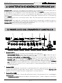
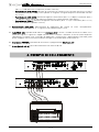
3. PANNELLO DI COLLEGAMENTO E CONTROLLO
1. Sezione INPUTS.
Questa sezione comprende i connettori e controlli di ingresso all’amplificatore.
- Selettore [SENSITIVITY]: selettore della bassa (posizione L) o alta (posizione H) sensibilità di ingresso
dell’amplificatore. La differenza tra le due sensibilità è di 10 dB.
- Connettori [LEFT], [RIGHT] e [PEDAL/MONO]: connettori jack bilanciati di ingresso all’amplificatore.
Con l’utilizzo con gli strumenti della serie Legend collegare le uscite [LEFT] e [RIGHT] agli stessi di
Hurricane 210. Se si desidera amplificare l’uscita [PEDALS] dello strumento, collegarla a
[PEDAL/MONO], così come con qualsiasi strumento con uscita audio monofonica. Dato che Hurricane
210 è equipaggiato con due amplificatori interni, l’ingresso [LEFT] invia il segnale all’amplificatore degli
altoparlanti di sinistra, [RIGHT] lo invia a quelli di destra. L’ingresso[PEDAL/MONO] invia il segnale ad
entrambi gli altoparlanti.
2. Sezione LINKS.
Questa sezione comprende i connettori da cui è possibile prelevare il segnale proveniente dallo strumento
collegato agli omonimi connettori della sezione INPUTS e da reinviare ad un secondo Hurricane 210
oppure altri sistemi di amplificazione per il collegamento in serie di più diffusori.
3. Sezione EQUALIZER.
Questa sezione comprende i controlli dell’equalizzatore interno semi-parametrico di cui è equipaggiato
Hurricane 210.
- Potenziometro [LOW]: permette di regolare l’attenuazione (da 0 a -12 dB in serigrafia) o l’esaltazione
2
3
4
5 6
1

IT - 3
Manuale Utente
(da 0 a +12 dB) delle basse frequenze (inferiori ai 200 Hz).
- Potenziometro [MID FREQ]: permette di selezionare la frequenza che viene poi attenuata o esaltata
dal potenziometro [MID GAIN]. Come riportato in serigrafia, il range di frequenze selezionabili è di 200
Hz – 2 KHz.
- Potenziometro [MID GAIN]: permette di regolare l’attenuazione (da 0 a -12 dB) o l’esaltazione (da 0 a
+12 dB) dei segnali attorno alla frequenza regolata con il potenziometro [MID FREQ].
- Potenziometro [HIGH]: permette di regolare l’attenuazione (da 0 a -12) o l’esaltazione (da 0 a +12)
delle alte frequenze (superiori ai 4 KHz).
4. Potenziometro [VOLUME]: potenziometro di regolazione del volume di uscita all’amplificatore.
Posizionando la manopola su “0 “ il segnale risulta completamente chiuso.
5. Led [PEAK ON]: quando verde indica che Hurricane 210 è acceso. Quando acceso rosso indica che il
livello del segnale in ingresso è troppo elevato ed è in funzione il limitatore al fine di evitare distorsioni
indesiderate. In questo caso si consiglia di abbassare il livello tramite il potenziometro [VOLUME] (vedi
punto 4) oppure sullo strumento trasmittente collegato ai connettori della sezione INPUTS.
6. Interruttore [POWER]: interruttore di accensione e spegnimento di Hurricane 210.
7. Presa [MAINS AC-IN]: presa di alimentazione alla corrente di rete.
4. ESEMPIO DI COLLEGAMENTO
Conn.
[LEFT]
Conn.
[RIGHT]
Conn.
[PEDALS]
viscount Legend
viscount Hurricane 210
viscount Hurricane 210

IT - 4
Manuale Utente
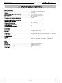
5. SPECIFICHE TECNICHE
AMPLIFICATORE
Caratteristiche .................................................................. Classe D 2 canali biamplificati
Potenza ............................................................................. 4x 150W
THD+N (da 0.1 W a 1/2 potenza) ................................... < 0,1% (tipico < 0,05%)
Alimentazione ................................................................... Input universale, con PFC
Tensione d’esercizio ........................................................ 85 – 264 VAC
Consumo (1/4 potenza massima) ................................... 150 W
CARATTERISTICHE ELETTRICHE
Impedenza di ingresso .................................................... 15 KOhm (bilanciato)
Risposta in frequenza ...................................................... 40 – 18000 Hz
Frequenza di cross-over ................................................. 800 Hz @ 24 dB / oct., attivo
Filtro subsonico ................................................................ Si
Protezione alta frequenza ............................................... PTC
ACUSTICA
Altoparlanti ........................................................................ 2x Woofer (10”), 2x Mid Range (4”), 2x Tweeter
Max SPL ............................................................................ 120 dB (spazio libero)
CONTROLLI ...................................................................... Sensibilità di ingresso, Equalizzatore (Low – Mid Gain
– Mid Freq – High), Volume
CONNESSIONI
Ingressi ............................................................................. 3x jack ¼” bilanciati (Left – Right – Pedal/Mono)
Link .................................................................................... 3x jack ¼”bilanciati (Left – Right – Pedal/Mono)
BOX
Mobile ................................................................................ Laminato di betulla
Finitura .............................................................................. Vernice nera antigraffio
Protezione ......................................................................... Griglie metalliche
Dimensioni (A x L x P) ..................................................... 69 x 51,5 x 48,5 cm
Peso (Kg) .......................................................................... 41

Smaltimento dei rifiuti elettrici ed elettronici (applicabile nell’Unione Europea e negli altri paesi
europei con servizio di raccolta differenziata)
Ai sensi dell’art. 13 del Decreto legislativo 25 luglio 2005, n. 151 “Attuazione delle Direttive
2002/95/CE, 2002/96/CE e 2003/108/CE”
II simbolo presente sul prodotto o sulla sua confezione indica che il prodotto non verrà trattato come
rifiuto domestico. Sarà invece consegnato al centro di raccolta autorizzato per il riciclo dei rifi uti
elettrici ed elettronici. Assicurandovi che il prodotto venga smaltito in modo adeguato, eviterete un
potenziale impatto negativo sull’ambiente e la salute umana, che potrebbe essere causato da una
gestione non conforme dello smaltimento del prodotto. Il riciclaggio dei materiali contribuirà alla
conservazione delle risorse naturali. Per ricevere ulteriori informazioni più dettagliate Vi invitiamo a
contattare l’uffi cio preposto nella Vostra città, il servizio per lo smaltimento dei rifi uti o il negozio in
cui avete acquistato il prodotto.
Lo smaltimento del prodotto da parte dell’utente comporta l’applicazione delle sanzioni amministrative
previste dalla normativa di legge.
Questo prodotto è conforme ai requisiti delle direttive EMCD 2004/108/EC e LVD 2006/95/EC.


EN - 1
User Manual
INDEX
1. Important notes .............................................................................................................................................1
1.1 Looking after the product .............................................................................................................................. 1
1.2 Connections ................................................................................................................................................... 1
1.3 Notes about the manual ................................................................................................................................ 1
2. General characteristics of Hurricane 210 ......................................................................................................2
3. Connection and control panel .......................................................................................................................2
4. Connection example .....................................................................................................................................3
5. Technical specifications ................................................................................................................................4
1. IMPORTANT NOTES
1.1 LOOKING AFTER THE PRODUCT
Do not apply excessive force to the instrument’s structures or the controls (buttons, connectors, etc.).
When possible, do not place the instrument close to units which generate strong interference, such as
radios, TVs, computer videos, etc.
Do not place the instrument close to heat sources, in damp or dusty places or in the vicinity of strong
magnetic fields.
Do not expose the instrument to direct sunlight.
Never insert foreign bodies inside the instrument or pour liquids of any kind into it.
To clean the case, use only a soft brush or compressed air.
1.2 CONNECTIONS
Before making the connections, ensure that all spekares you are using are off. This will prevent noisy or
even dangerous signal peaks.
If the instrument is to be out of use for lengthy periods, disconnect the plug from the power socket.
Connect the power cable to an earthed socket.
Check that the voltage corresponds to the voltage shown on the serial number plate of the device.
Clean periodically the power cable.
Only use the power cable provided with the instrument.
Do not place the power cable close to heat sources Do not damage the cable or bend it overmuch.
Do not place heavy objects on the cable. Do not place the cable where it could be trampled.
1.3 NOTES ABOUT THE MANUAL
Take good care of this manual.
This manual is an integral part of the instrument. The descriptions and illustrations in this publication are
not binding.
While the instrument’s essential characteristics remain the same, the manufacturer reserves the right to
make any modifications to parts, details or accessories considered appropriate to improve the product or
for requirements of a constructional or commercial nature, at any time and without undertaking to update
this publication immediately.
All rights reserved; the reproduction of any part of this manual, in any form, without the manufacturer’s
specific written permission is forbidden.
All the trademarks referred to in this manual are the property of the respective manufacturers.
Read all the information carefully in order to obtain the best performances from your product and waste no
time.
The codes or numbers in square brackets ([ ]) indicate the names of the controls and connectors of the
device. For example, [VOLUME] refers to the VOLUME potentiometer.

EN - 2
User Manual
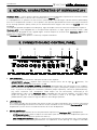
2. GENERAL CHARACTERISTICS OF HURRICANE 210
Hurricane 210 is a stereo speaker specially designed with the collaboration of professional musicians, to offer
a portable amplification system for the instruments of the Legend series.
It is equipped with six speakers on two channels (two woofers, two mid-ranges and two tweeters) powered by
four class D amplification sections. These speakers are specially positioned to enhance the internal emulation
of the rotating speakers (Rotary effect) of the electromechanical organs with which the Legend series are
equipped.
The amplifiers provide exceptional sound quality, high sound pressure level and a linear frequency response.
Hurricane 210 is also equipped with a semi-parametric equalizer, an input signal sensitivity control, audio
inputs specially designed for the Legend organs and link outputs to connect other Hurricane 210 or other
amplification and diffusion systems.
The Hurricane 210 stereo speaker is extremely compact and robust.
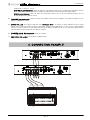
3. CONNECTION AND CONTROL PANEL
1. INPUTS Section.
This section includes connectors and input controls to the amplifier.
- [SENSITIVITY] selector: amplifier input sensitivity selector switch, low or high (L / H position). The
difference between the two sensitivities is 10 dB.
- [LEFT], [RIGHT] and [PEDAL/MONO] connectors: balanced input jack connectors to the amplifier.
With the use of the Legend series instruments, connect the [LEFT] and [RIGHT] outputs to the Hurricane
ones. If you wish to amplify the instrument's [PEDALS] output separately, connect to [PEDAL/MONO].
Any other instrument with monophonic audio output can be conveniently connected to the
[PEDAL/MONO] input. Since Hurricane 210 is equipped with two internal amplifiers, the [LEFT] input
sends the signal to the left speaker amplifier, the [RIGHT] sends it to the right speakers. The
[PEDAL/MONO] input sends the signal to both the left and right speakers.
2. LINKS Section.
This section includes the connectors from which to take the signal coming from the instrument connected
to the corresponding connectors of the INPUTS section and to be sent to a second Hurricane 210 or other
amplification systems for the cascade connection of several loudspeakers.
3. EQUALIZER Section.
This section includes controls for the semi-parametric equalizer that Hurricane 210 is equipped with.
- [LOW] potentiometer: allows to adjust the attenuation (from 0 to -12 dB) or the amplification (from 0 to
+12 dB) of the low frequencies (lower than 200 Hz).
- [MID FREQ] potentiometer: allows to select the central frequency of intervention that is attenuated or
enhanced by the [MID GAIN] potentiometer. As reported in screen printing, the range of selectable
2
3
4
5 6
1

EN - 3
User Manual
frequencies is 200 Hz - 2 KHz.
- [MID GAIN] potentiometer: allows to adjust the attenuation (from 0 to -12 dB) or the exaltation (from 0
to +12 dB) of the signals around the frequency adjusted with the potentiometer [MID FREQ].
- [HIGH] potentiometer: allows to adjust the attenuation (from 0 to -12) or the exaltation (from 0 to +12)
of high frequencies (above 4 KHz).
4. [VOLUME] potentiometer: allows to adjust the output volume to the amplifier. Turning the knob to "0” the
signal is completely silent.
5. [PEAK ON] Led: when green indicates that Hurricane 210 is on. When lit red it indicates that the input
signal level is too high and the limiter is working to avoid unwanted distortion. In this case it is advisable to
lower the level by means of the potentiometer [VOLUME] (see point 4) or on the transmitting instrument
connected to the connectors of the INPUTS section.
6. [POWER] switch: Hurricane 210 switch on and off.
7. [MAINS AC-IN] socket: mains power supply socket.
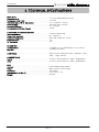
4. CONNECTION EXAMPLE
Conn.
[LEFT]
Conn.
[RIGHT]
Conn.
[PEDALS]
viscount Legend
viscount Hurricane 210
viscount Hurricane 210

EN - 4
User Manual
5. TECHNICAL SPECIFICATIONS
AMPLIFIER
Characteristics ................................................................. 2 x Class D biamplified channels
Total power (1% THD) ..................................................... 4x 150W
THD+N (from 0.1 W to 1/2 power) .................................. < 0.1% (typical < 0.05%)
Power Supply .................................................................... Universal input, with PFC
Operating Voltage ............................................................ 85 – 264 VAC
Consumption (1/4 Max Power) ........................................ 150 W
ELECTRICAL CHARACTERISTICS
Input impedance .............................................................. 15 KOhm (balanced)
Frequency response ........................................................ 40 – 18000 Hz
Crossover frequency ....................................................... 800 Hz @ 24 dB / oct., active
Subsonic filter ................................................................... Yes
HF Protection .................................................................... PTC
ACOUSTICS
Loudspeakers ................................................................... 2x Woofer (10”), 2x Mid Range (4”), 2x Tweeter
Max SPL ............................................................................ 120 dB (free space)
CONTROLS ....................................................................... Input Sensitivity, Equalizer (Low – Mid Gain – Mid
Freq. – High), Volume
CONNECTIONS
Inputs ................................................................................ 3x jack ¼” balanced (Left – Right – Pedal/Mono)
Links .................................................................................. 3x jack ¼” balanced (Left – Right – Pedal/Mono)
BOX
Cabinet .............................................................................. Laminated birch polywood
Finish ................................................................................. Black scratch-resistant paint
Protection .......................................................................... Metal grids
Dimensions (H x W x D)................................................... 27.2" x 20.3" x 19"
Weight ............................................................................... 90,4 lbs

Disposal of old Electrical & Electronic Equipment (Applìcable throughout the European Union
and other European countries with separate collection programs)
Dir. 2002/95/CE, 2002/96/CE e 2003/108/CE
This syrnbol, found on your product or on its packaging, indicates that this product should not be
treated as household waste when you wish to dispose of it. Instead, it should be handed overt to an
applicable collection point for the recycling of electrical and electronic equipment. By ensuring this
product is disposed of correctly, you will help prevent potential negative consequences to the
environment
and human health, which could otherwise be caused by inappropriate disposal of this product. The
recycling of materials will help to conserve natural resources. For more detailed information about the
recycling of this product, please contact your local city offi ce, waste disposal service or the retail store
where you purchased this product.
This product complies with the requirements of EMCD 2004/108/EC and LVD 2006/95/EC.
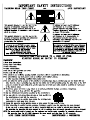
FCC RULES
NOTE: This equipment has been tested and found to comply with the limits for a Class B digital Device, persuant to Part 15 if the FCC
Rules. These limits are designed to provide reasonable protection against harmful interference in a residential installation. This
equipment generates, uses and can radiate radio frequency energy and, if not installed and used in accordance with the instruction,
may cause harmful interference to radio comunications. However, there is no guarantee that the interference will not occur in a
particular installation. If this equipment does cause harmful interference to radio or television reception, which can be determinated by
turning the equipment off and on, the user is encuraged to try to correct the interference by one or more of the following measures:
- Reorient or relocate the receiving antenna.
- Increase the separation between the equipment and receiver.
- Connect the equipment into an outlet on a circuit different from that to which the receiver is connected.
- Consult the dealer or an experienced Radio/Tv technician for help.
The user is cautioned that any changes or modification not expressly approved by the party responsable for compliance could void the
user’s authority opearate the equipment.
INFORMATIONS FCC
NOTE : Cet instrument a été controlé et il est garanti pour etre en conformité avec les spécifications techniques établies pour les
dispositifs numériques de la « Classe B » selon les normes de protection contre les interférences avec d’autres dispositifs électroniques
environnants. Cet appareil produit et utilise des fréquences radio. S’il n’est pas installé et utilisé selon les instructions contenues dans le
mode d’emploi, il peut générer des interférences. L’observation des normes FCC ne garanti pas qu’il y aura aucune interférence. Si cet
appareil est la cause d’ interférences avec une réception Radio ou TV, il est possible
de le vérifier en éteignant puis en allumant l’instrument : Vous pouvez alors résoudre le problème en suivant les procédures suivantes :
- déplacer ou orienter l’antenne de l’appareil avec lequel se manifeste l’interférence.
- déplacer cet instrument ou l’appareil avec lequel se produit l’interférence
- connecter cet instrument à une prise de courant différente afin de mettre les deux appareils sur deux circuits différents.
- consulter le revendeur ou un technicien radio/tv pour d’autres renseignements.
D’éventuelles modifications non approuvées par le constructeur peuvent annuler votre garantie de l’appareil.

Viscount International S.p.A.
Via Borgo, 68 / 70 – 47836 Mondaino (RN), ITALY
Tel: +39-0541-981700 Fax: +39-0541-981052
Website: www.viscountinstruments.com
-
 1
1
-
 2
2
-
 3
3
-
 4
4
-
 5
5
-
 6
6
-
 7
7
-
 8
8
-
 9
9
-
 10
10
-
 11
11
-
 12
12
-
 13
13
-
 14
14


Viscount Hurricane 210 Manuale del proprietario
- Categoria
- Altoparlanti
- Tipo
- Manuale del proprietario
in altre lingue
Documenti correlati
-
Viscount LEGEND LIVE Manuale del proprietario
-
Viscount V3.12A Manuale utente
-
-
Viscount Legend Solo Manuale del proprietario
-
-
Viscount Vivace 30 Deluxe Manuale utente
-
-
-
-