
Documentazione
Tecnica
47
rev. 3.3
12/2003
©
CAME
CANCELLI
AUTOMATICI
C 100 / C BY / C BYT
CANCELLI AUTOMATICI
ITALIANO/ENGLISH/ ESPAÑOL
119C47-1
SERIE C |
C SERIES
|
SERIE C
75
3
2
486 1 6
TX
TX
RX
RX
4x1
2x1
2x1
4x1
6x1,5
2x1,5
TRG58
3x1
3x1,5
230V
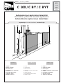
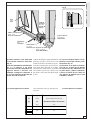
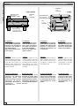
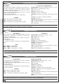
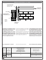
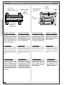
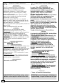
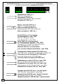
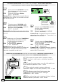
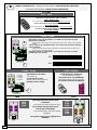
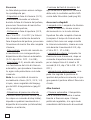
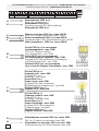
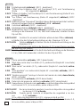
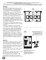
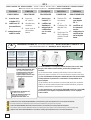
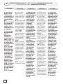
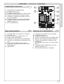
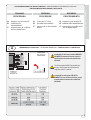
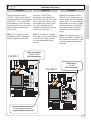
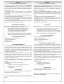
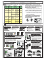
1. Gruppo C
2. Quadro comando
3. Ricevitore radio
4. Lampeggiatore di movimento
5. Antenna
6. Fotocellule di sicurezza
7. Selettore a chiave
8. Maniglia di sblocco
1. C unit
2. Control panel
3. Radio receiver
4. Flashing movement warrning light
5. Antenna
6. Safety photocells
7. Key-operated selector switch
8. Release handle
1. Grupo C
2. Cuadro de mando
3. Radioreceptor
4. Làmpara intermitente de movimiento
5. Antena
6. Fotocélula de seguridad
7. Selector con Ilave
8. Tirador de desbloqueo
Automazioni per applicazioni industriali
Automation systems for industrial applications
Automatización aplicaciones industriales
Impianto tipo -
Standard installation -
Instalaciòn tipo
Impianto tipo
Sandard installation
Instalacion tipo

-2-
ITALIANO • ENGLISH • ESPAÑOL
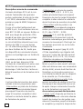
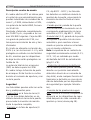
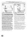
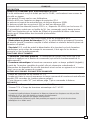
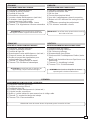
Caratteristiche generali
Attenzione! Controllate che le apparecchiature di comando, di sicurezza e gli accessori siano originali CAME; ciò
garantisce e rende l'impianto di facile esecuzione e manutenzione.
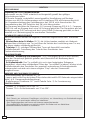
Accessori di completamento:
ZC3-ZC5-ZM2 quadro comando per C BY - C 100.
ZT4 quadro comando per C BYT.
CCT catena da 1/2".
CGIU giunto per catena.
C1-C2S per portoni sezionali.
C1P-C2P per portoni scorrevoli, a scomparsa ed a libro.
C1-C2F per finestre wasistas ed a sporgere.
C1-C2H per serrande.
CMS dispositivo di sblocco con maniglia e cordino comple-
to di chiavi personalizzate.
CGP guida per catena e carter di protezione per portoni
scorrevoli.
Descrizione:
- Motoriduttori idonei alla movimentazione di portoni sezio-
nali, a scomparsa, scorrevoli, a libro, finestre wasistas ed
a sporgere, serrande a scorrimento orizzontale o verticale
con palo rotante.
- Progettati e costruiti interamente dalla CAME Cancelli
Automatici S.p.A.,
- Grado di protezione IP 54.
- Garantiti 24 mesi salvo manomissioni.
Modelli:
C100 - Motoriduttore irreversibile 300W.
CBY - Motoriduttore irreversibile 450W.
CBYT - Motoriduttore irreversibile trifase 600W.
Modelos:
C100 - Motorreductor irreversible 300W.
CBY - Motorreductor irreversible 450W.
CBYT - Motorreductor irreversible trifase 600W.
Descripción:
- Motorreductores idóneos para mover puertas secciona-
les, ocultas, correderas, articulads, ventanas abatibles y
salientes, puertas enrollables con deslizamiento horizon-
tal o vertical con eje rotatorio.
- Diseñado y fabricado enteramente por CAME Cancelli
Automatici S.p.A.,
- Grado de protección IP54.
- Garantizado 24 meses, salvo manipulaciones.
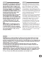
Atención! Comprobar que los equipos de mando, de seguridad y los acesorios sean originales CAME; lo cual garantiza
y facilita el uso y el mantenimiento del aparato.
Características Generales
Accesorios que lo completan:
ZC3-ZC5-ZM2 cuadro de mando para C BY - C 100.
ZT4 cuadro de mando para C BYT.
CCT cadena de 1/2".
CGIU unión para cadena.
C1-C2S para puertas seccionales.
C1P-C2P para puertas correderas, ocultas y articulados.
C1-C2F para ventanas abatibles y salientes.
C1-C2H para puertas enrollables.
CMS dispositivo de desbloqueo con manilla y cuerda con
llaves personalizadas.
CGP guía para cadenay cubierta de proteccion para puer-
tas de corredera.
Description:
- Gearmotors designed to action sectional doors, folding
doors, sliding or hinged doors, wasistas and hinged win-
dows and vertical or horizontal rotating pole shutters.
- Designed and constructed entirely by CAME Cancelli
Automatici S.p.A.
- IP 54 protecting rating.
- Guaranteed for 24 months, unless tampered with by un-
authorized personnel.
Attention! to insure easy installation and conformance with current safety norms, we raccomend installation of CAME
safety and control accessories.
General specifications
Accessories for installation:
ZC3-ZC5-ZM2 control panel for C BY - C 100.
ZT4 control panel for C BYT.
CCT 1/2" chain.
CGIU coupling for chain.
C1-C2S for sectional doors.
C1P-C2P for sliding doors, folding doors, hinged doors.
C1-C2F for wasistas and hinged windows.
C1-C2H for shutters.
CMS release mechanism with handle and cable, complete
with keys.
CGP chain guide and protection casing of sliding gates.
Models:
C100 - 300W non-reversible gearmotor.
CBY - 450W non-reversible gearmotor.
CBYT - 600W three-phase non-reversible gearmotor.
ESPAÑOL
ITALIANO
ENGLISH

-3-
ITALIANO • ENGLISH • ESPAÑOL
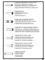
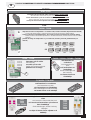
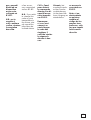
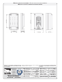
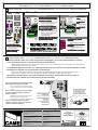
210
250
280
k
y
180
133
87
x
353
160
180
C 100C BY/C BYT
205
x
= min. 147 max. 175
y
= min. 186 max. 213
k
= min. 333 max. 388
65
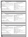
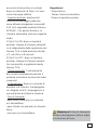
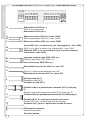
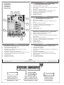
Dati relativi ai valori di alimentazione nomi-
nale.
*Regolabile mediante quadri comando
CAME.
N.B.: in nessun caso può essere affidata
all'irreversibilità del motoriduttore, la sicu-
rezza anticaduta nelle movimentazioni a
scorrimento verticale (es: sezionali).
These technical specifications apply when unit
is powered at nominal voltage.
*Adjustable using CAME control panels.
N.B.: when fitted to vertical-opening doors (e.g.
sectional doors), the non-reversibility of the
gearmotor must never be used as a safety
device to prevent accidental falling. A specific
safety device must be fitted.
Datos relativos a los valores de alimenta-
ción nominal.
*Regulable mediante cuadros de mando
CAME.
NOTA: durante los movimientos con desli-
zamiento vertical (ej: seccionales) no se
puede, en ningún caso, confiar en la irre-
versibilidad del motorreductor para la se-
guridad anticaída.
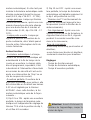
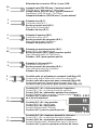
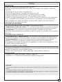
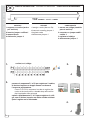
Caratteristiche tecniche -
Technical features
- Descripción técnica
Tipo Peso Alimentazione Corrente
nominale
Potenza Intermittenza
lavoro
Rapporto di
riduzione
Coppia Velocità di
rotazione
Condensatore
Type Weight Power supply Nominal
current
Power Duty cycle Reduction ratio Torque Speed of
rotation
Capacitor
Tipo Peso Alimentación Corriente
nominal
Potencia Intermit.
trabajo
Relación
de reduc.
Par Velocidad
de rotac.
Condensador
Kg V A W % i N.m rpm µF
C 100 8.5
230
2.3 300
30
1/32 26 * 42 20
C BY
18.5
4450
1/30
50 *
45
31.5
C BYT 230 - 400 2 - 1.2 600 50 50 -
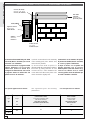
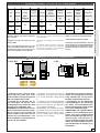
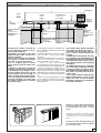
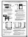
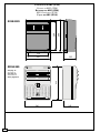
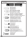
Misure di ingombro -
External dimensions
- Dimensiones máximas
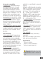
Controlli preliminari -
Preliminary checks
- Controlas preliminares
- Controllare che non vi sia attrito tra
parti fisse e mobili e la struttura del
serramento sia adeguatamente robu-
sta.
- Controllare che il percorso dei cavi
elettrici sia eseguito secondo le di-
sposizioni di comando e sicurezza
(vedi impianto tipo).
NOTA: le applicazioni che seguono
sono solo degli esempi in quanto lo
spazio per il fissaggio del motore e
degli accessori varia a seconda de-
gli ingombri e pertanto spetta all'in-
stallatore la soluzione più idonea.
- Check that there is no friction between
moving parts and fixed parts and that
the structure of the door is sufficiently
robust.
- Check that the path of the electrical
wiring is in compliance with the safety
and control instructions (see Standard
installation).
N.B.: the applications shown below are
examples. Since the space available for
installation of the motor and the acces-
sories varies, the installer should se-
lect the most suitable solution.
- Controbar que no haya roce entre
las partes fijas y móviles y la estruc-
tura del cerramiento sea adecuada-
mente robusta.
- Controbar que el recorrido de los
cables eléctricos esté realizado se-
gún las disposiciones de mando y
seguridad (véase instalation están-
dar).
NOTA: las aplicaciones siguientes
son sólo ejemplos, porque el espa-
cio para la fijación del motor y de
los accesorios varía según las di-
mensiones, por lo tanto es deber del
instalador encontrar la solución más
idónea.

-4-
ITALIANO • ENGLISH • ESPAÑOL
CBY/CBYT
CBY/CBYT
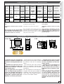
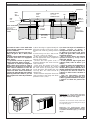
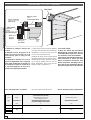
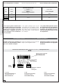
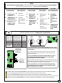
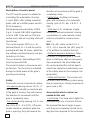
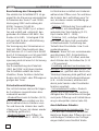
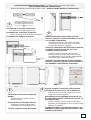
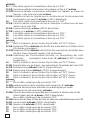
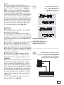
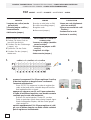
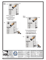
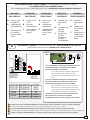
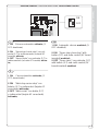
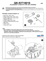
Portone sezionale -
Sectional door
- Puerta seccional
1) Portare l'anta a circa metà della
corsa.
2) Adattare il foro del pignone a 36
denti (accessorio C1-C2S) al Ø del
palo-molla e fissarlo con saldatura.
3) Fissare il motore col pignone del-
lo stesso allineato col pignone a 36
denti, sbloccarlo (tirare la staffa A) e
collegare la catena da 1/2" tra i due
pignoni, in modo tale che questa non
sia in tensione.
1) Move the door to approximately the
half-open position.
2) Adapt the hole of the 36-tooth pinion
(C1-C2S accessory) to suit the diame-
ter of the spring-roller and weld into po-
sition.
3) Fit the motor with its pinion, in align-
ment to the 36-tooth pinion. Release the
motor by pulling bracket "A" and con-
nect the 1/2" between the two pinion.
N.B. The chain should be slightly taut.
1) Colocar la hoja a la mitad de la
carrera.
2) Adaptar el agujero del piñón de
36 dientes (accesorio C1-C2S) al Ø
del eje-muelle y fijarlo soldándolo.
3) Fijar el motor con el piñón del
mismo alineandolo con el piñón de
36 dientes, desbloquearlo (tirar del
estribo A) y colocar la cadena de 1/
2" entre los dos piñones de manera
que no esté sometida a tensión.
Con questa applicazione si ottiene:
This application gives the following per-
formance:
Con esta aplicación se obtiene:
Pignone (36 denti)
Pinion (36 teeth)
Piñón (36 dientes)
Palo-molla
Spring-roller
Barra-muelle
Pignone motore
Motor pinion
Piñón motor
Catena da 1/2”
1/2” chain
Cadena da 1/2”
Staffa A
Bracket A
Estribo A
Anta
Door
Hoja
Tipo Coppia Giri del pignone Z=36
(con finecorsa di serie)
Velocità di rotazione
albero condotto
Ty p e To r qu e Pinion revolutions Z=36
(with standar limit stop)
Speed of rotation
of driven shaft
Typ Par Giros del piñón Z=36
(con final de carrera de serie)
Velocidad de rotación
árbol conducido
N·m n° rpm
C 100 62
14
17.5
C BY
120 18.5
C BYT

-5-
ITALIANO • ENGLISH • ESPAÑOL
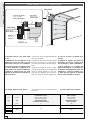
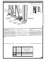
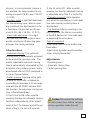
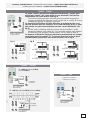
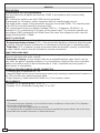
Fig. A
Finestra wasistas -
Wasistas window
- Ventana abatibles
1) Portare l'anta/e a circa metà della
corsa, fissare il motore e sbloccarlo
(fig. A).
2) Inserire nell'albero di trasmissione
(da 1") il pignone a 15 denti
(accessorio C1-C2F), alineandolo col
pignone motore e fissarlo con
saldatura. Collegare la catena da 1/
2" tra i due pignoni in modo tale che
questa non sia in tensione.
1) Move the wing/s to approximately the
half-open position, fit the motor and
action the release mechanism (fig. A).
2) Fit the 15-tooth pinion (accessory C1-
C2F) to the drive shaft (the 1"), in align-
ment with the motor pinion, and weld
into position. Fit the 1/2" chain to the
two pinions. The chain should be slight-
ly taut.
1) Colocar la hoja/las hojas a la mi-
tad de la carrera, fijar el motor y des-
bloquearlo (fig. A).
2) Introducir en el árbol de transmi-
sión (de 1") el piñón de 15 dientes
(accesorio C1-C2F), alineandolo con
el piñón motor y fijarlo soldándolo.
Colocar la cadena de 1/2" entre los
dos piñones de manera que no esté
sometida a tensión.
This application gives the following per-
formance:
Con questa applicazione si ottiene: Con esta aplicación se obtiene:
Anta
Wing
Hoja
Albero di trasmissione
Drive shaft
Arbol de trasmission
Cremagliera
Rack
Cremallera
Catena da1/2”
1/2” chain
Cadena de 1/2”
Pignone (15 denti)
Pinion (15 teeth)
Piñón 815 dientes)
Pignone motore
Motor pinion
Piñón motor
Staffa di
fissaggio
Bracket
Estribo de
fijacion
Tipo Coppia Velocità di rotazione albero condotto
Ty pe Torque Speed of rotation of driven shaft
Typ Par Velocidad de rotaziòn à rbol conducido
N·m rpm
C 100 26 42
C BY
50 45
C BYT

-6-
ITALIANO • ENGLISH • ESPAÑOL
C BY/C BYT
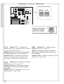
1) Inserire all'estremità del palo della
serranda (Ø max. 60.4 mm), la corona
e fissarla con saldatura.
2) Fissare il motore col pignone dello
stesso allineato con la corona,
sbloccarlo (tirare la staffa A) e
collegare la catena da 1/2" tra corona
e pignone motore in modo tale che
questa non sia in tensione.
1) Fit the crown wheel to the extremity
of the rotating pole (max. Ø 60.4 mm)
and weld into position.
2) Fit the motor with its pinion in
alignment with the crown wheel. Release
the motor by pulling bracket "A" and
connect the 1/2" chain between the
crown wheel and the motor pinion. The
chain should be slightly taut.
1) Introducir en el extremo del eje de
la puerta enrollable (Ø máx. 60.4 mm)
la corona y fijarla soldándola.
2) Fijar el motor con el piñón del
mismo alineado con la corona,
desbloquearlo (tirar del estribo A) y
colocar la cadena de 1/2" entre
corona y piñón motor de manera que
no esté sometida a tensión.
Con questa applicazione si ottiene:
This application gives the following
performance:
Con esta aplicación se obtiene:
Corona (60 denti)
60-tooth crow wheel
Corona (60 dientes)
Pignone motore
Motor pinion
Piñón motor
Staffa A
Bracket A
Estribo A
Catena da 1/2”
1/2” chain
Cadena de 1/2”
Palo della
serranda
Rotating pole
Eje de la puerta
Type Coppia Giri della corona Z=60
(con finecorsa di serie)
Velocità di rotazione
albero condotto
Typ e Torque Crown wheel revolutions Z=60
(with standar limit stop)
Speed of rotation
of driven shaft
Typ Par Giros de la corona Z=60
(con final de carrera de serie)
Velocidad de rotación
árbol conducido
N·m n° rpm
C 100 100
8.5
10.5
C BY
200 11
C BYT
Serranda con palo rotante -
Rotating-pole shutters
- Puerta enrollable con eje rotatorio

-7-
ITALIANO • ENGLISH • ESPAÑOL
C BY/C BYT
B
CGP
Fig. 2Fig. 1
Portone scorrevole a due ante -
Two-wing sliding doors
- Puerta corredera a dos hojas
1) Portare le ante a circa metà della
corsa, fissare il motore e sbloccarlo
(tirare la staffa A).
2) Applicare l'accessorio C1P (per C
100), C2P (per C BY / C BYT) come
segue:
- fissare il rinvio tendicatena opposto
al motore ed in asse con il pignone
dello stesso;
- se presente, fissare la guida per
catena (CGP) tra motore e rinvio;
- applicare la catena (la lunghezza
della catena, deve essere 2 volte la
distanza B). Regolare la tensione
della stessa mediante la vite del
rinvio e bloccare i dadi. N.B.: la
catena non deve essere in tensione;
- fissare gli appositi attacchi (staffe e
piastre) prima alla catena e poi alle
ante e aplicare il carter di protezione
(CGP).
1) Move the wings to approximately the
half-open position and fit the motor.
Release the motor by pulling bracket
"A".
2) Fit accessory C1P (for C 100) or C2P
(for C BY / CBYT) as follows:
- fit the chain tensioner attachment on
the side opposite the motor, in alignment
with the motor pinion;
- position the chain guide (CGP, if
featured) between the motor and the
chain tensioner;
- fit the chain (the length of the chain
should be twice distance "B"). Adjust
the chain tension by turning the screw
on the tensioner, then tighten the nuts
securely. N.B.. the chain should be
slightly taut;
- fit the brackets and plates first to the
chain and then to the wings and fit the
protective cover (CGP).
1) Colocar las hojas a la mitad de la
carrera, colocar el motor y
desloquearlo (tirar del estribo A).
2) Aplicar el accesorio C1P (para
C100), C2P (para CBY / CBYT) de la
siguiente manera:
- fijar el renvío tensor de cadena
opuesto al motor y en eje con el
piñón del mismo;
- si está presente, fijar la guía para
cadena (CGP) entre el motor y el
renvío;
- aplicar la cadena (la longitud de la
cadena debe ser el doble de la
distancia B). Regular la tensión de la
misma mediante el tornillo del renvío
y bloquear las tuercas. Nota: la
cadena no debe estar sometida a
tensión;
- fijar los adecuados ancajes
(estribos y placas) primero a la
cadena y posteriormente a las hojas
y aplicar el cárter de protección
(CGP).
Attenzione: le sopraccitate istruzioni
valgono anche su portone scorrevole sia a
libro (fig.1) che ad un'anta (fig.2).
Important: the instructions shown above are
also applicable to book-type sliding doors (fig.1)
and sigle-wing (fig.2).
Atención!: las instrucciones amba
mencionadas se refieren también a puertas
correderas articuladas (fig.1) y a una hoja
(fig.2).
Dado
Nut
Tuerca
Vite
Bolt
Tornillo
Rinvio tendicatena
Chain tensioner
attachment
Renvio tensor de
cadena
Piastra
Plate
Placa
Catena da 1/2”
1/2” chain
Cadena de 1/2”
Staffa A
Bracket A
Estribo A
Pignone
motore
Motor pinion
Piñón motor
Luce netta
Net aperture
Luz neta
Staffa
Bracket
Estribo

-8-
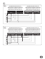
ITALIANO • ENGLISH • ESPAÑOL
UVW056T78
FC FA
F
TEWVU
ZT4
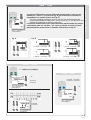
* Per aperture maggiori (10.5 m),
sostituire il pignone del gruppo finecorsa
con un pignone a 15 denti (C100) o con
pignone da 21 denti (CBY/CBYT), oppure
applicare dei finecorsa ausiliari
sostituendoli a quelli in dotazione.
* For wider apertures (10.5 m), replace the
limit stop pinion with a 15-tooth pinion
(C100) or a 21-tooth pinion (CBY/CBYT).
Alternatively, fit auxiliary limit stops in place
of the standard limit stops.
* Para aperturas mayores (10.5 m),
sustituir el piñón del grupo final de
carrera con un piñón de 15 dientes
(C100) o con un piñón de 21 dientes
(CBY/CBYT), o bien aplicar finales de
carrera auxiliares que sustituyan los
suministrados.
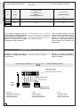
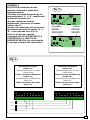
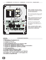
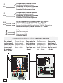
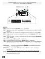
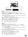
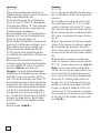
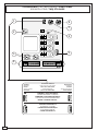
Collegamenti elettrici -
Electrical connections
- Conexiones eléctricas
Installare il quadro comando e
procedere ai collegamenti elettrici
come indicato.
Install the electrical control panel and
connect the wiring as indicated.
Instalar el cuadro de mando y
proceder a las conexiones eléctricas
segùn lo indicado.
Quadro comando per CBYT |
control panel for CBYT
| Cuadro de mando para CBYT
Quadro comando
Control panel
Cuadro de mando
Morsettiera motore
Motor terminal block
Caja de bornes para el motor
U - V - W
Collegamento motore 1-2
Connection to motor 1-2
Conexión motor 1-2
Cortocircuitare
Short circuit
Cortocircuitar
0 - FC
Finecorsa chiude
Limit switch closure
Fin de carrera cierre
0 - FA
Finecorsa apre
Limit switch aperture
Fin de carrera apertura
Massa
Ground
Tierra
Con questa applicazione si ottiene:
This application gives the following
performance:
Con esta aplicación se obtiene:
Type Spinta Apertura *
(con finecorsa di serie)
Velocità di traslazione
Ty pe Thrust Aperture *
(with standar limit stop)
Speed of movement
Typ Empuje Apertura *
(con final de carrera de serie)
Velocidad de traslación
N·m m m/min
C 100 850 2 - 6 8
C BY
1500 0 - 6.5 8.5
C BYT
La pagina si sta caricando...

-10-
ITALIANO • ENGLISH • ESPAÑOL
C 100C BY - C BYT
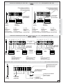
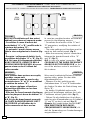
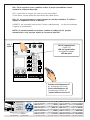
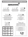
Regolazioni dei microinterruttori -
Adjusting the microswitches
- Regulación de los microinterruptores
In apertura
Portare l'anta/e in posizio-
ne di apertura desiderata.
Ruotare una manopola
nera fino a far inserire il
microinterruttore.
Bloccare la relativa mano-
pola azzurra.
Aperture
Move the gate(s) to the
desired aperture position.
Turn one of the black knobs
until the microswitch is
tripped, then tighten the
corresponding light blue
knobs securely.
En fase de apertura
Llevar la/s hoja/s en la
posición de apertura
deseada. Girar una
manecilla negra hasta
introducir el micro-
interruptor. Bloquear la
correspon- diente
manecilla azul.
In chiusura
Portare l'anta/e in posi-
zione di chiusura. Ruo-
tare l'altra manopola
nera fino a far inserire
il microin terruttore.
Bloccare la relativa ma-
nopola azzurra.
Closure
Move the gate(s) to the
closed position. Turn the
second black knob until
the microswitch is tripped,
then tighten the corre-
sponding light blue knob
securely.
En fase de cierre
Colocar la/s hoja/s en la
posición de cierre. Girar
la otra manecilla negra
hasta introducir el micro-
interruptor. Bloquear la
correspondiente maneci-
lla azul.
In apertura
Portare l'anta/e in posizio-
ne di apertura desiderata.
Ruotare una vite fino a far
inserire il microinter-
ruttore nel nottolino di
scorrimento.
In chiusura
Portare l'anta/e in posi-
zione di chiusura. Ruo-
tare l'altra vite fino a far
inserire il microinter-
ruttore nel nottolino.
Aperture
Move the gate(s) to the ap-
erture position. Turn one of
the screws until the mi-
croswitch is inserted into
the sliding pawl.
Closure
Move the gate(s) to the
closed position. Turn the
second screw until the
microswitch is inserted
into the sliding pawl.
En fase de apertura
Llevar la/s hoja/s en la
posición de apertura de-
seada. Enroscar un torni-
llo hasta introducir el mi-
crointerruptor en el trin-
quete.
En fase de cierre
Colocar la/s hoja/s en
la posición de cierre.
Enroscar el otro torni-
llo hasta introducir el
microinterruptor en el
trinquete.
Manopole nere
Black Knobs
Manecillas negras
Nottolino
Pawl
Trinquete
Manopole blu
Light blu Knobs
Manecillas azules
Microinteruttori
Microswitches
Microinterruptores
Viti
Screws
Tornillos
Nottolino
Pawl
Trinquete

-11-
ITALIANO • ENGLISH • ESPAÑOL
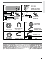
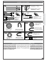
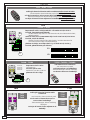
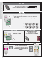
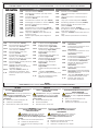
CMS CGP
C 1P
C 2P
C1-C2H C1-C2S
CCT
CGIU
C1-C2F
60,4 mm
34 mm
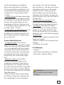
Il gruppo non necessita di alcuna manu-
tenzione specifica. Solo come misura
cautelativa e in caso di servizio intensi-
vo è opportuno controllare la tensione
della catena e le parti di contatto tra
struttura fissa e mobile (es. guide e ca-
relli su portoni scorevoli e cerniere su
quelli a libro, etc.).
This unit requires no specific maintenance.
However, as a precaution and in case of
heavy-duty service, it is advisable to check
the chain tension and to check for friction
between fixed and moving parts (e.g.
guides and slides on sliding doors, hing-
es on book-type doors, etc.).
El conjunto no necesita ningún manteni-
miento específico. Sólo como medida
cautelar y en caso de uso intenso es
conveniente controlar la tensión de la
cadena y las partes de contacto entre
estructura fija y móvil (ej.: guías y ca-
rretes en las puertas correderas y bisa-
gras en las articuladas, etc.).
Manutenzioni periodiche -
Periodic maintenance
- Mantenimiento periódico
Carter (L= 1,5/2 m)
Casing (L= 1,5/2 m)
Carter (L= 1,5/2 m)
Guida per catena (L=1,5/2 m)
Chain guide (L=1,5/2 m)
Guia para cadena (L=1,5/2 m)
Piastra
Plate
Placa
Rinvio tendicatena
Chain tensioner
attachment
Renvio tensor de
cadena
Staffa
Bracket
Placca
Piastra
Plate
Placa
Rinvio tendicatena
Chain tensioner
attachment
Renvio tensor de
cadena
Corona (60 denti)
60 tooth crown whell
Corona (60 dientes)
Catena da 1/2” (130 passi)
1/2” chain (130 links)
Cadena de 1/2” (130 pasos)
Pignone (36 denti)
Pinion (36 teeth)
Piñón (36 dientes)
Catena da 1/2” (78 passi)
1/2” chain (78 links)
Cadena de 1/2” ( 78 Pasos)
Pignone (15 denti)
Pinion (15 teeth)
Piñón (15 dientes)
Catena da 1/2” ( 78 passi)
1/2” chain (78 links)
Cadena de 1/2” ( 78 pasos)
Catena da 1/2” ( L= 5 m)
1/2” chain ( L= 5 m)
Cadena de 1/2” ( L= 5 m)
Giunto
Coupling
Unión
Staffa -
Bracket
- Placca
Accessori -
Accessories
- Accesorios

CANCELLI AUTOMATICI
CAME LOMBARDIA S.R.L.______COLOGNO M. (MI)
(+39) 02 26708293 (+39) 02 25490288
CAME SUD S.R.L. ___________________NAPOLI
(+39) 081 7524455 (+39) 081 7529109
CAME (AMERICA) L.L.C.____________MIAMI ( FL)
(+1) 305 5938798 (+1) 305 5939823
CAME AUTOMATISMOS S.A__________MADRID
(+34) 091 5285009 (+34) 091 4685442
CAMEBELGIUM NU-SA_______________LESSINES
(+32) 068 333014 (+32) 068 338019
CAME FRANCE S.A.____NANTERRE CEDEX ( PARIS)
(+33) 01 46130505 (+33) 01 46130500
CAME GMBH________KORNTAL BEI (STUTTGART)
(+49) 07 15037830 (+49) 07 150378383
CAME GMBH____________SEEFELD BEI (BERLIN)
(+49) 03 33988390 (+49) 03 339885508
CAME PL SP.ZO.O______________WARSZAWA
(+48) 022 8365076 (+48) 022 8369920
CAME UNITED KINGDOM LTD___NOTTINGHAM
(+44) 01159 210430 (+44) 01159 210431
CAME CANCELLI AUTOMATICI S.P.A.
DOSSON DI CASIER (TREVISO)
(+39) 0422 4940 (+39) 0422 4941
SISTEMA QUALITÀ
CERTIFICATO
ASSISTENZA TECNICA
NUMERO VERDE
800 295830
W
EB
www.came.it
E-
MAIL
Tutti i dati sono stati controllati con la massima cura. Non ci assumiamo comunque
alcuna responsabilità per eventuali errori od omissioni.
All data checked with the maximum care. However, no liability is accepted for any
error or omission.
Todos los datos se han controlado con la máxima atención. No obstante no nos
responsabilizamos de los posibles errores u omisiones.
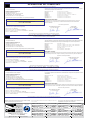
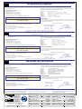
DICHIARAZIONE DEL FABBRICANTE
Ai sensi dell’Allegato II B della Direttiva Macchine 98/37/CE
I Rappresentanti della
CAME Cancelli Automatici S.p.A.
via Martiri della Libertà, 15
31030Dosson di Casier - Treviso - ITALYtel
(+39) 0422 4940 - fax (+39) 0422 4941
internet: www.came.it - e-mail: [email protected]
Dichiarano sotto la propria responsabilità che i/il prodotto/i denominato/i ...
… sono conformi alle disposizioni legislative Nazionali che traspongono le seguenti Direttive
Comunitarie (dove specificatamente applicabili):
DIRETTIVA MACCHINE 98/37/CE
DIRETTIVA BASSA TENSIONE 73/23/CEE - 93/68/CEE
DIRETTIVA COMPATIBILITÀ ELETTROMAGNETICA 89/336/CEE - 92/31/CEE
DIRETTIVA R&TTE 1999/5/CE
Inoltre, dichiara che il/i prodotto/i, oggetto della presente dichiarazione, sono costruiti nel rispetto
delle seguenti principali norme armonizzate:
EN 292 PA RT E 1ª E 2ª SICUREZZA DEL MACCHINARIO.
EN 12453 CHIUSURE INDUSTRIALI, COMMERCIALI …
EN 12445 CHIUSURE INDUSTRIALI, COMMERCIALI …
EN 60335 - 1 SICUREZZA NEGLI APPARECCHI AD USO DOMESTICO ...
EN 60204 - 1 SICUREZZA DEL MACCHINARIO.
EN 50081 - 1 E 2COMPATIBILITÀ ELETTROMAGNETICA.
EN 50082 - 1 E 2COMPATIBILITÀ ELETTROMAGNETICA.
AVVERTENZA IMPORTANTE!
È vietato mettere in servizio il/i prodotto/i, oggetto della presente dichiarazione, prima del
completamento e/o incorporamento, in totale conformità alle disposizioni della Direttiva
Macchine 98/37/CE
Firma dei Rappresentanti
Documentazioni tecniche specifiche dei prodotti sono disponibili a richiesta!
Data della presente dichiarazione 07/12/2001
Also, they furthermore represent and warrant that the product/s that are the subject of the present
Declaration are manufactured in the respect of the following main harmonized provisions:
EN 292 PART 1 AND 2MACHINERY SAFETY.
EN 12453 INDUSTRIAL, COMMERCIAL AND OTHER CLOSING MECHANISMS.
EN 12445 INDUSTRIAL, COMMERCIAL AND OTHER CLOSING MECHANISMS.
EN 60335 - 1 SAFETY IN APPARATUSES FOR HOME USE.
EN 60204 - 1 MACHINERY SAFETY.
EN 50081 - 1 AND 2ELECTROMAGNETIC COMPATIBILITY.
EN 50082 - 1 AND 2ELECTROMAGNETIC COMPATIBILITY.
IMPORTANT CAUTION!
It is forbidden to market/use product/s that are the subject of this declaration before completing and/
or incorporating them in total compliance with the provisions of Machinery Directive 98/37/CE
Signatures of the Representatives
Specific technical documentation on the products is available on request!
Date of the present declaration 07/12/2001
MANUFACTURER’S DECLARATION
As per Enclosure II B of Machinery Directive 98/37/CE
The representatives of
CAME Cancelli Automatici S.p.A.
via Martiri della Libertà, 15
31030 Dosson di Casier - Treviso - ITALY
tel (+39) 0422 4940 - fax (+39) 0422 4941
internet: www.came.it - e-mail: [email protected]
Hereby declare, under their own respons ibility, that the product/s called ...
… comply with the Italian National Legal Provisions that transpose the
following Community Directives (where specifically applicable):
MACHINERY DIRECTIVE 98/37/CE
LOW VOLTAGE DIRECTIVE 73/23/EEC - 93/68/EEC
LECTROMAGNETIC COMPATIBILITY DIRECTIVE 89/336/EEC - 92/31/EEC
R&TTE DIRECTIVE 1999/5/CE
DECLARACION DEL FABRICANTE
De conformidad con el Anexo II B de la Directiva de Máquinas 98/37/CE
Fecha de la presente declaración 07/12/2001Adjunta a la documentación técnica (el original de la Declaración está disponible previa petición)
Los Representantes de la compañía
CAME Cancelli Automatici S.p.A.
via Martiri della Libertà, 15
31030 Dosson di Casier - Treviso - ITALY
tel (+39) 0422 4940 - fax (+39) 0422 4941
internet: www.came.it - e-mail: [email protected]
Declaran bajo su responsabilidad que el/los producto/s denominado/s ...
… cumplen con las disposiciones legislativas nacionales que trasponen las siguientes
Directivas Comunitarias (donde específicamente aplicables):
DIRECTIVA DE MÁQUINAS 98/37/CE
DIRECTIVA DE BAJA TENSIÓN 73/23/CEE - 93/68/CEE
DIRECTIVA DE COMPATIBILIDAD ELECTROMAGNÉTICA 89/336/CEE - 92/31/CEE
DIRECTIVA R&TTE 1999/5/CE
Los productos objeto de esta declaración están fabricados respetando las siguientes normas
armonizadas:
EN 292 PA RTE 1ª Y 2ª SEGURIDAD DE LAS MÁQUINAS.
EN 12453 CIERRES INDUSTRIALES, COMERCIALES …
EN 12445 CIERRES INDUSTRIALES, COMERCIALES …
EN 60335 - 1 SEGURIDAD DE LOS APARATOS PARA USO DOMÉSTICO...
EN 60204 - 1 SEGURIDAD DE LAS MÁQUINAS.
EN 50081 - 1 E 2COMPATIBILIDAD ELECTROMAGNÉTICA.
EN 50082 - 1 E 2COMPATIBILIDAD ELECTROMAGNÉTICA.
AVVERTENZA IMPORTANTE!
Está prohibido hacer uso de el/los producto/s, objeto de la presente declaración antes de completarlo/
s y/o incorporarlo/s en total conformidad a las disposiciones de la Directiva de Máquinas 98/37/CE.
Firma de los Representantes
Documentación técnica específica de los productos está disponible previa petición
Enclosed with the technical documentation (the original copy of the Declaration is available on request)
Allegata alla documentazione tecnica (l’originale della Dichiarazione è disponibile a richiesta)
RESPONSABILE TECNICO
Sig. Gianni Michielan
PRESIDENTE
Sig. Paolo Menuzzo
TECHNICAL MANAGER
Mr. Gianni Michielan
MANAGING DIRECTOR
Mr. Paolo Menuzzo
RESPONSABLE TÉCNICO
Sr. Gianni Michielan
PRESIDENTE
Sr. Paolo Menuzzo
C100 • C-BY • C-BYT
C1-P • C1-C2F • C1-C2H • C1-C2S • C2-P
CCT • CGIU • CGP • CMS
C100 • C-BY • C-BYT
C1-P • C1-C2F • C1-C2H • C1-C2S • C2-P
CCT • CGIU • CGP • CMS
C100 • C-BY • C-BYT
C1-P • C1-C2F • C1-C2H • C1-C2S • C2-P
CCT • CGIU • CGP • CMS
La pagina si sta caricando...
La pagina si sta caricando...
La pagina si sta caricando...
La pagina si sta caricando...
La pagina si sta caricando...
La pagina si sta caricando...
La pagina si sta caricando...
La pagina si sta caricando...
La pagina si sta caricando...
La pagina si sta caricando...
La pagina si sta caricando...
La pagina si sta caricando...

Documentazione
Tecnica
S34
rev. 2.1
02/2001
©
CAME
CANCELLI
AUTOMATICI
319S34
SCHEDA COMANDO
CONTROL
BOARD
CARTE DE COMMANDE
STEUERPLATINE
TARJETA DE MANDO
SERIE Z |
Z SERIES
/ SÉRIE Z |
BAUREIHE Z |
SERIE Z
ZC4
CANCELLI AUTOMATICI
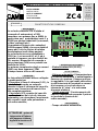
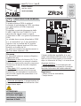
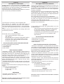
DESCRIZIONE
La scheda comando ZC4 è adatta al
comando di automazioni a 230V
monofase con potenza fino a 600W, in
particolare per i motoriduttori serie C e
F3000 per portoni industriali (scorrevoli,
a libro, sezionali etc.).
Va montata all’interno dei contenitori
S4339 oppure S4340, che sono dotati di
presa per il riciclo d’aria e di relativo
trasformatore (vedi ultima pagina).
La scheda deve essere alimentata a
230V (a.c.) sui morsetti L1 e L2, ed é
protetta in ingresso con due fusibili da
5A, mentre i dispositivi di comando a
bassa tensione (24V) sono protetti con
fusibile da 3,15A.
La potenza complessiva degli accessori
(24V) non deve superare i 20W.
Il tempo lavoro è fisso a 80 secondi.
SICUREZZA
Le fotocellule possono essere collegate
e predisposte per:
-
Riapertura
in fase di chiusura (2-C1), le
fotocellule rilevando un ostacolo
durante la fase di chiusura del cancello,
provocano l'inversione di marcia fino
alla completa apertura;
-
Stop totale
(1-2), arresto del cancello
con l'esclusione del ciclo di chiusura
automatica, per riprendere il movimento
del cancello, agire sulla pulsantiera o
sul radiocomando;
ACCESSORI COLLEGABILI
-
Elettroserratura
24V (11-ES);
ALTRE FUNZIONI
-
Chiusura automatica.
Il temporizzatore
di chiusura automatica si autoalimenta a
finecorsa in apertura. Il tempo prefissa-
to regolabile, è in ogni modo subordina-
to dall'intervento di eventuali accessori
di sicurezza e si esclude dopo un
intervento di "stop" o in mancanza
d'energia elettrica;
-
"Uomo presente"
. Funzionamento del
cancello mantenendo premuto il pulsan-
te (esclude la funzione del
radiocomando);
REGOLAZIONI
- Tempo chiusura automatica;
CARATTERISTICHE GENERALI
ITALIANO
ATTENZIONE : prima di
intervenire all'interno
dell'apparecchiatura,
togliere la tensione di
linea
FUS. CENTR ALIN A
T.C.A.
1
2
ZC4
QUADRO
COMANDO
FUSI BILI LINEA
L1TL2T CT 0 2412
PROG
La pagina si sta caricando...
La pagina si sta caricando...

-4-
1
2 3 4
L2T
L1T
02412
FUS . CENTRALI N A
T.C.A.
1 2
ZC4
QUADRO
COMANDO
FUSI BILI LIN EA
L1T L2T CT 0 24
12
PROG
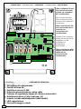
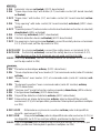
SCHEDA BASE -
MOTHERBOARD
- CARTE BASE -
GRUNDPLATINE
- TARJETA BASE
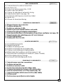
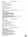
COMPONENTI PRINCIPALI
1 Morsettiere di collegamento
2 Fusibili di linea 5A
3 Fusibile accessori 3,15A
4 Pulsante memorizzazione codice radio
5 Trimmer di regolazione tempo di chiusura automatica
6 Selettore funzioni a 2 dip (vedi pag. 14)
7 Innesto scheda radiofrequenza (vedi tabella)
8 LED segnalazione
9 Fori per fissaggio scheda
ITALIANO
1
2
3
4
5
6
7
8
9
Nota: collegare i fili neri
che fuoriescono dalla
scheda sui connettori
del condensatore.
NB: connect the black
wires coming out of the
board to the condenser’s
connectors.
Note: connecter les fils
noirs qui sortent de la
carte sur les
connecteurs du
condensateur.
Hinweis: Die schwarzen
Kabel, die von der Karte
wegführen, an die
Verbinder am
Kondensator
anschließen.
Nota: conectar los hilos
negros que salen de la
tarjeta en los
conectores del
condensador.
La pagina si sta caricando...
La pagina si sta caricando...

-7-
11
FA
2
7
Lampada spia (24V-3W max.) "cancello chiuso"
(24V-3W max.) "gate-closed" signal lamp
Lampe-témoin (24V-3W max.) "portail fermeture"
Signallampe (24V-3W max.) "Tor Schließen"
Lámpara indicadora (24V-3W max.) "puerta cierre"
Pulsante stop (N.C.)
Pushbutton stop (N.C.)
Bouton-poussoir arrêt (N.F.)
Stop-Taste (N.C.)
Pulsador de stop (N.C.)
Contatto radio e/o pulsante per comando
Contact radio and/or button for control
Contact radio et/ou poussoir pour commande
Funkkontakt und/oder Taste Steuerart
Contacto radio y/o pulsador para mando
Contatto (N.C.) di «riapertura durante la chiusura»
Contact (N.C.) for «re-opening during the closing»
Contact (N.F.) de «réouverture pendant la fermeture»
Kontakt (Ruhekontakt) «Wiederöffnen beim Schliessen»
Contacto (N.C.) para la «apertura en la fase de cierre»
Collegamento (N.C.) finecorsa apre
Connection (N.C.) limit switch opens
Connexion (N.F.) fin de course ouverture
Anschluß (N.C.) Endschallter Öffnung
Conexión (N.C.) fin de carrera apertura
Collegamento (N.C.) finecorsa chiude
Connection (N.C.) limit switch closes
Connexion (N.F.) fin de course fermeture
Anschluß (N.C.) Endschallter Schließung
Conexión (N.C.) fin de carrera cierre
Collegamento antenna
Antenna connection
Connexion antenne
Antennenanschluß
Conexión antena
2
C1
F
FA
1
2
F
FC

-8-
A
max
300W
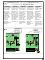
COLLEGAMENTO PER 2 MOTORI ABBINATI -
CONNECTIONS FOR 2 COMBINED MOTORS
CONNEXIONS POUR 2 MOTEURS ACCOUPLÉS
ANSCHLUSSE FÜR 2 PARALLELGESCHALTETEN MOTOREN
- CONEXIÓN PARA 2 MOTORES ACOPLADOS
In case two combined motors are installed,
proceed in the following manner:
- Coordinate the direction of the "A" and
"B" gearmotors, modifying the rotation of
motor "B";
- The same settings and functions must be
made on both control panels (fig. 1).
- Make the necessary electric connections
between the terminal boards of the "A"
and "B" (fig. 2);
N.B. In case of a paired connection, THE
COUPLING OF THE RADIO FREQUENCY
BOARD IS NOT PROVIDED FOR, so the
use of the wireless control is excluded in
this instance.
ENGLISH
Pour installer deux moteurs accouplés,
procéder comme suit:
- Coordonner le sens de marche des
motoréducteurs "A" et "B" en modifiant
la rotation du moteur "B";
- Les mêmes réglages et fonctions
doivent être effectués sur les deux
tableaux (fig. 1).
- Effectuer les branchements électriques
entre les plaques à borne du tableau "A"
et "B" (fig. 2);
N.B. En cas de branchement accouplé,
LA CARTE RADIOFRÉQUENCE N'EST
PAS PRÉVUE et l'utilisation de la
radiocommande est donc exclue.
FRANÇAIS
Wenn zwei kombinierte Motoren installiert
werden sollen, gehen Sie dazu bitte
folgendermaßen vor:
- Stimmen Sie die Laufrichtung der
Getriebemotoren "A" und "B" aufeinander
ab. Andern Sie dazu die Drehrichtung vom
Motor "B";
- An beiden Schalttafeln müssen die
gleichen Einstellungen erfolgen. Auch die
Funktionen müssen gleich sein (fig. 1);
-Führen Sie die elektrischen Anschlüsse
zwischen den Klemmbretter von Schalttafel
"A" und "B" so durch, wie auf (fig. 2)
Hinweis. Bei kombiniertem Anschluß IST
KEIN EINSTECKEN DER RADIO-
FREQUENZKARTE VORGESEHEN, d.h.
daß die Verwendung von Fernbedienungen
ausgeschlossen ist.
DEUTSCH
Nel caso d'installazione di due motori
abbinati, procedere nel seguente modo:
- Coordinare il senso di marcia dei
motoriduttori "A" e "B", modificando la
rotazione del motore "B";
- Su entrambi i quadri devono essere
fatte le stesse regolazioni e funzioni (fig.
1);
- Eseguire i collegamenti elettrici tra le
morsettiere del quadro "A" e "B" (fig. 2);
N.B. Nel caso di collegamento abbinato,
NON È PREVISTO L'INNESTO DELLA
SCHEDA RADIOFREQUENZA, di conse-
guenza viene escluso l'utilizzo del
radiocomando.
ITALIANO
B
max
300W
La pagina si sta caricando...

-10-
LIMITATORE DI COPPIA MOTORE /
MOTOR TORQUE LIMITER
/ LIMITEUR DE COUPLE MOTEUR
DREHMOMENTBEGRENZER DES MOTORS
/ LIMITADOR DE PAR MOTOR
1
234
L2T
L1T
02412
L1TL2T CT 0 2412
Per variare la coppia motrice, spostare il faston
indicato (con filo di colore nero) su una delle 4 posizioni;
1 min. - 4 max
To vary the motor torque, move the indicated faston
to one of the four positions: 1 min. - 4 max
Pour varier le couple du moteur, déplacer le
connecteur indiqué sur l'une des 4 positions; 1 min. - 4 max
Zur Änderung des Motor-Drehmoments den
angegebenen Faston auf eine der 4 Stellungen
positionieren: 1 min. - 4 max
Para variar el par motor, desplazar el faston indicado
hasta una de las 4 posiciones: 1 min. - 4 max
I
GB
F
D
E
SELEZIONI & REGOLAZIONI -
SELECTIONS & ADJUSTMENTS -
SÉLECTIONS & RÉGLAGES
FUNKTIONSWAHL & EINSTELLUNGEN -
SELECCIÓNES & REGULACIONES
T.C .A.
1 2
S
M
ON
OFF
REGULACIÓN TRIMMERS
EI NTE LL U NG TRIM MERS
RÉGLAGE TRIMMERS
TRIMMERS ADJUSTMENT
REGOLAZIONE TRIMMERS
T.C.A.
1 2
1 OFF "Operator present" disabled: radio
remote control is deactivated when
function is selected; (1 ON - enabled)
2 ON Automatic closing enabled;
(2 OFF - disabled)
Trimmer T.C.A.
= Adjusts automatic closing time
from a minimum of 3 seconds to a maximum of 120
seconds.
GB
1 OFF Bedienung vom "Steuerpul" deaktiviert:
bei Wahl dieser Betriebsart wird die
Funkfernsteuerung ausgesch.;
(1 ON - aktiviert)
2 ON Schließautomatik aktiviert;
(2 OFF - deaktiviert)
Trimmer T.C.A.
= Timer, auf dem die
Verzögerung für das automatische Schlißen mit
mindestens 3 Sekunden und höchstens 120
Sekunden eingestellt werden kann.
D
1 OFF "Hombre presente" desactivado:
escluye la función del mando de radio;
(1 ON - activado)
2 ON Cierre automático activado;
(2 OFF - desactivado)
Trimmer T.C.A.
= Réglage du temps de fermeture
automatique d'un minimum de 3 secondes à un
maximun de 120 secondes.
E
1 OFF "Homme mort" désactivèe: exclut la
fonction radiocommande;
(1 ON activée)
2 ON Fermeture automatique activée;
(2 OFF - désactiée)
Trimmer T.C.A.
= Réglage du temps de fermeture
automatique d'un minimum de 3 secondes à un
maximun de 120 secondes.
F
1 OFF "Uomo presente" disattivato: esclude
il funzionamento del radiocomando;
(1 ON - attivato)
2 ON Chiusura automatica attivata;
(2 OFF - disattivata)
Trimmer T.C.A.
= Regolazione tempo di chiusura
automatica da un minimo di 3 secondi a un mas-
simo di 120 secondi.
I
La pagina si sta caricando...
La pagina si sta caricando...

-13-
A
.
1 2
PROG
ENGLISH
PROCEDURE
A. insert an
AF card **.
B. encode
transmitter/s.
C. store code in
the
motherboard.
FRANÇAIS
PROCEDURE
A. placer une
carte AF **.
B. codifier le/s
émetteur/s.
C. mémoriser la
codification
sur la carte
base.
DEUTSCH
PROZEDUR
A. Stecken Sie
eine Karte
AF **.
B. Codieren Sie
den/die
Sender.
C. Speichern Sie
die Codierung
auf der
Grundplatine.
ITALIANO
PROCEDURA
A. inserire una
scheda AF **.
B. codificare il/i
trasmettitore/i.
C. memorizzare la
codifica sulla
scheda base.
ZC4
INSTALLAZIONE DEL RADIOCOMANDO -
RADIO
CONTROL
INSTALLATION
-
INSTALLATION DE LA RADIOCOMMANDE
INSTALLATION
DER
RADIOSTEUERUNG
-
INSTALACIÓN DEL RADIOMANDO
ESPANOL
PROCEDIMIENTO
A. introducir
una tarjeta
AF **.
B. codificar el/
los
transmisor/
es.
C. memorizar la
codificación
en la tarjeta
base.
(**) Per trasmettitori con frequenza 433.92 AM (serie TOP e serie
TAM) bisogna, sulla relativa scheda AF43S, posizionare il jumper
come illustrato.
(**) On AM transmitters operating at 433.92 MHz (TOP and TAM
series), position the jumper connection on circuit card AF43S as
shown on the sheet.
(**) Pour les émetteurs de fréquence 433.92 AM (série TOP et
série TAM) il faut positionner le pontet sur la carte AF43S
correspondante de la façon indiquée.
(**) Bei Sendern mit einer Frequenz von 433.92 AM (Reihe TOP und
Reihe TAM) ist der auf der entsprechenden Platine AF43S befindliche
Jumper der Abbildung entsprechend zu positionieren.
(**) Para transmisores con frecuencia 433.92 AM (serie TOP y
serie TAM) es necesario, en la tarjeta corespondiente AF43S,
colocar el jumper como se indica
TOP
TAM
SCHEDA BASE
MOTHERBOARD
CARTE DE BASE
BASISKARTE
TARJETA BASE
SCHEDA "AF"
"AF" BOARD
CARTE "AF"
KARTE «AF»
TARJETA «AF»
La schedina AF deve essere inserita OBBLIGATORIAMENTE in assenza di tensione, perché la scheda madre la riconosce solo quando viene alimentata
The AF board should ALWAYS be inserted when the power is off because the motherboard only recognises it when it is powered.
La carte AF doit OBLIGATOIREMENT être branchée en l’absence de tension car la carte mère ne la reconnaît que quand elle est alimentée.
Vor Einschieben der Karte die Stromzufuhr UNBEDINGT abschalten, da die Erkennung durch die Hauptkarte nur über eine Neueinschaltung ( nur durch Versorgung) erfolgt.
La tarjeta AF se debe montar OBLIGATORIAMENTE en caso de falta de corriente, porque la tarjeta madre la reconoce sólo cuando está alimentada
zHM/azneuqerF
zHM/ycneuqerF
zHM/ecneuqerF
zHM/zneuqerF
zHM/aicneucerF
azneuqerfoidaradehcS
draobycneuqerfoidaR
ecneuqérfoidaretraC
enitalP-zneuqerfknuF
aicneucerfoidaratejraT
erotittemsarT
rettimsnarT
ruettemE
rednesknuF
rosimsnarT
599.62MF 031FA MFT
009.03MF 051FA MFT
29.334MA
MS34FA/S34FA POT/MAT
RS34FA OMOTA
INSERIMENTO SCHEDA AF -
AF BOARD INSERTION
- NSTALLATION DE LA CARTE AF
EINSTECKEN DER KARTE AF /
MONTAJE DE LA TARJETA AF
A

-14-
AT01 - AT02
vedi foglio istruzioni inserito nella confezione
della scheda AF43SR
see instruction sheet inside the pack of AF43SR circuit card
voir les instructions qui se trouve dans l'emballage
de la carte AF43SR
Siehe Anleitungen, die der Packung beiliegen der Platine AF43SR
ver hoja de instrucciones adjunta en el embalaje
de la tarjeta AF43SR
ATOMO
CODIFICA TRASMETTITORI -
TRANSMITTER ENCODING
- CODIFICATION DES EMETTEURS
CODIERUNG DER SENDER
- CODIFICACIÓN TRANSMISORES
B
vedi istruzioni su confezione
see instructions on pack
voir instructions sur l'emballage
Siehe Anleitungen auf der Packung.
ver instrucciones en el embalaje
T432S / T432SAT434M - T314M
impostare solo il codice
set code only
ne saisir que le code
Stellen Sie nur den Code ein.
plantear sólo el código
P1=CH1
P2=CH2
P3=CH3
P4=CH4
1 2 3 4 5 6 7 8 9 10
C
P1 P2
P3 P4
TOP
impostare il codice sul dip-switch C e il canale su D (P1=CH1 e P2=CH2,
impostazione di default)
set the code to dip-switch C and channel to D (P1=CH1 and P2=CH2, default
setting)
saisir le code sur le commutateur dip C et le canal sur D (P1=CH1 et P2=CH2,
saisie de défaut)
Stellen Sie den Code auf den Dip-Switch C und den Kanal auf D (P1=CH1
und P2=CH2; Grundeinstellung).
plantear el código en el dip-switch C y el canal en D (P1=CH1 y P2=CH2,
planteamiento por defecto)
T432M - T312M
1 2 3 4 5 6 7 8 9 10
1 2 3 4
C
D
P1 P2
P2
CH1 CH2 CH3
CH4
P1
CH1 CH2 CH3
CH4
1 2 3 4 1 2 3 4 1 2 3 41 2 3 4
1 2 3 4 1 2 3 4 1 2 3 4 1 2 3 4
vedi foglio istruzioni inserito nella
confezione
see instruction sheet inside the pack
voir la notice d'instructions qui se
trouve dans l'emballage
Siehe Anleitungen, die der Packung
beiliegen.
ver hoja de instrucciones adjunta en el
embalaje
TAM
T132
T134
T138
T152
T154
T158
T432
T434
T438
TFM

-15-
ITALIANO
-Tenere premuto
il tasto "PROG"
sulla scheda
base (il led di
segnalazione
lampeggia), con
un tasto del
trasmettitore
s'invia il codice,
il led rimarrà
acceso a
segnalare
l'avvenuta
memorizzazione
(vedi fig.1).
DEUTSCH
-Halten Sie die
Taste PROG an
der Basiskarte
gedrückt (die
Kontrolleuchte
blinkt). Senden
Sie den Code
mit einer Taste
vom Sender. Der
Kontrolleuchte
bleibt jetzt an
und zeigt
dadurch das
erfolgte
Speichern an
(Abb.1).
ESPANOL
-Mantener
oprimida la tecla
"PROG" en la
tarjeta base (el
led de
señalización
parpadea), con
una tecla del
transmisor se
envía el código,
el led
permanece
encendido para
indicar que el
almacenamendo
se ha efectuado
(fig.1).
ENGLISH
-Keep the PROG
key pressed on
the base card
(the signal LED
will flash), and
with a key on the
transmitter the
code is sent, the
LED will remain
lit to signal the
successful
saving of the
code (figure 1).
FRANÇAIS
-Appuyer sur la
touche "PROG"
sur la carte de
base (le led de
signalisation
clignote), avec
une touche du
emetteur on
envoie le code,
le led restera
allumé pour
signaler que la
mémorisation
s'est effectuèe
(fig.1).
MEMORIZZAZIONE CODICE -
CODE STORAGE
- MEMORISATION DU CODE
SPEICHERN VOM CODE
- MEMORIZACIÓN CÓDIGO
C
T.C.A.
1 2
PROG
LED acceso
Lit LED
LED allumé
LED Kontrolleuchte
LED encendido
T.C.A.
1 2
PROG
LED intermittente
flashing LED
LED clignotant
LED Aufblinkende
LED intermitente
fig. 1
La pagina si sta caricando...

Documentazione
Tecnica
S33
rev. 2.4
01/2006
©
CAME
CANCELLI
AUTOMATICI
319S33
SCHEDA COMANDO
CONTROL
BOARD
CARTE
DE COMMANDE
STEUERPLATINE
TARJETA
DE MANDO
SERIE Z | Z SERIES / SÉRIE Z | BAUREIHE Z | SERIE Z
ZC3
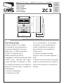
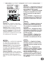
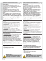
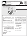
CARATTERISTICHE GENERALI
Descrizione quadro
Il quadro elettrico ZC3 è adatto
al comando di una automazione
per portoni industriali scorrevoli
della serie C e F3000, alimentati
a 230V con potenza fino a
600W, frequenza 50÷60 Hz.
Progettato e costruito interamente dalla
CAME S.p.A., risponde alle vigenti
norme UNI 8612. Contenitore in ABS
con grado di protezione IP54, dotato di
presa per il riciclo d’aria e completo di
trasformatore.
Il circuito va alimentato
con tensione di 230V
(a.c.) nei morsetti L1- L2 e protetto
in ingresso con due fusibili da 5A,
mentre i dispositivi di comando a
bassa tensione sono protetti con
fusibile da 1A.
La potenza complessiva degli
accessori (24V) non deve superare i
20W.
Il quadro include la funzione di spunto
manovra. Questa funzione si attiva in
fase di inizio apertura e chiusura del
portone.
ITALIANO
240 mm
120 mm
145 mm
320 mm
La pagina si sta caricando...
La pagina si sta caricando...
La pagina si sta caricando...
La pagina si sta caricando...
La pagina si sta caricando...
La pagina si sta caricando...
La pagina si sta caricando...
La pagina si sta caricando...
La pagina si sta caricando...
La pagina si sta caricando...
La pagina si sta caricando...
La pagina si sta caricando...
La pagina si sta caricando...
La pagina si sta caricando...
La pagina si sta caricando...
La pagina si sta caricando...
La pagina si sta caricando...
La pagina si sta caricando...
La pagina si sta caricando...
La pagina si sta caricando...
La pagina si sta caricando...
La pagina si sta caricando...
La pagina si sta caricando...
La pagina si sta caricando...
La pagina si sta caricando...
La pagina si sta caricando...
La pagina si sta caricando...
La pagina si sta caricando...
La pagina si sta caricando...
La pagina si sta caricando...
La pagina si sta caricando...
La pagina si sta caricando...
La pagina si sta caricando...
La pagina si sta caricando...
La pagina si sta caricando...
La pagina si sta caricando...
La pagina si sta caricando...
La pagina si sta caricando...
La pagina si sta caricando...
La pagina si sta caricando...
La pagina si sta caricando...
La pagina si sta caricando...
La pagina si sta caricando...
La pagina si sta caricando...
La pagina si sta caricando...
La pagina si sta caricando...
La pagina si sta caricando...
La pagina si sta caricando...
La pagina si sta caricando...
La pagina si sta caricando...
La pagina si sta caricando...
La pagina si sta caricando...
La pagina si sta caricando...
La pagina si sta caricando...
La pagina si sta caricando...
La pagina si sta caricando...
La pagina si sta caricando...
La pagina si sta caricando...
La pagina si sta caricando...
La pagina si sta caricando...
La pagina si sta caricando...
La pagina si sta caricando...
La pagina si sta caricando...
La pagina si sta caricando...
La pagina si sta caricando...
La pagina si sta caricando...
La pagina si sta caricando...
-
 1
1
-
 2
2
-
 3
3
-
 4
4
-
 5
5
-
 6
6
-
 7
7
-
 8
8
-
 9
9
-
 10
10
-
 11
11
-
 12
12
-
 13
13
-
 14
14
-
 15
15
-
 16
16
-
 17
17
-
 18
18
-
 19
19
-
 20
20
-
 21
21
-
 22
22
-
 23
23
-
 24
24
-
 25
25
-
 26
26
-
 27
27
-
 28
28
-
 29
29
-
 30
30
-
 31
31
-
 32
32
-
 33
33
-
 34
34
-
 35
35
-
 36
36
-
 37
37
-
 38
38
-
 39
39
-
 40
40
-
 41
41
-
 42
42
-
 43
43
-
 44
44
-
 45
45
-
 46
46
-
 47
47
-
 48
48
-
 49
49
-
 50
50
-
 51
51
-
 52
52
-
 53
53
-
 54
54
-
 55
55
-
 56
56
-
 57
57
-
 58
58
-
 59
59
-
 60
60
-
 61
61
-
 62
62
-
 63
63
-
 64
64
-
 65
65
-
 66
66
-
 67
67
-
 68
68
-
 69
69
-
 70
70
-
 71
71
-
 72
72
-
 73
73
-
 74
74
-
 75
75
-
 76
76
-
 77
77
-
 78
78
-
 79
79
-
 80
80
-
 81
81
-
 82
82
-
 83
83
-
 84
84
-
 85
85
-
 86
86
-
 87
87
-
 88
88
-
 89
89
-
 90
90
-
 91
91
-
 92
92
-
 93
93
-
 94
94
-
 95
95
-
 96
96
-
 97
97
-
 98
98
-
 99
99
-
 100
100
-
 101
101
-
 102
102
-
 103
103
-
 104
104
-
 105
105
-
 106
106
-
 107
107
-
 108
108


CAME C serie Manuale utente
- Tipo
- Manuale utente
in altre lingue
- English: CAME C serie User manual
- français: CAME C serie Manuel utilisateur
- español: CAME C serie Manual de usuario
- Deutsch: CAME C serie Benutzerhandbuch
Documenti correlati
-
CAME ZC3 Manuale del proprietario
-
-
CAME ZR24 Manuale del proprietario
-
-
-
-
-
-
-
Altri documenti
-
Erone SEL2681R868-P4 Use And Installation Manual
-
-
Aprimatic TM4 Manuale utente
-
 quiko QK-KIT18016 Manuale utente
-
-
Olympia TK 10 Door Chain Manuale del proprietario
-
Nice Automation Climber Manuale del proprietario
-
Marantec Control 41 Manuale del proprietario
-
Genius FALCON K Istruzioni per l'uso
-
