
DANGER ET AVERTISSEMENT
Le montage de ce produit ne peut être effectué que par
des professionnels.
Le non respect des indications de la présente notice ne
saurait engager la responsabilité du constructeur.
Risque d’électrocution, de brûlures ou d’explosion
• l’installation et l’entretien de cet appareil ne doivent être
effectués que par du personnel qualié
• avant toute intervention sur l’appareil, coupez les
entrées tensions, court-circuitez le secondaire de
chaque transformateur de courant (PTI SOCOMEC) et
coupez l’alimentation auxiliaire de l’appareil
• utilisez toujours un dispositif de détection de tension
approprié pour conrmer l’absence de tension
• replacez tous les dispositifs, les portes et les couvercles
avant de mettre cet appareil sous tension
• utilisez toujours la tension assignée appropriée pour
alimenter cet appareil.
Si ces précautions n’étaient pas respectées, cela
pourrait entraîner des blessures graves.
Risque de détérioration de l’appareil
Veillez à respecter :
• la plage de tension d’alimentation auxiliaire
• la plage de fréquence du réseau 50 ou 60 Hz
• une tension maximum aux bornes des entrées tension
de 520 V AC phase/phase ou 300 V AC phase/neutre
• un courant maximum de 6 A aux bornes des entrées
courants (I1, I2 et I3)
FR
OPERATIONS PREALABLES
Pour la sécurité du personnel et du matériel, il est impératif
de bien s’imprégner du contenu de cette notice avant la
mise en service.
Au moment de la réception du colis contenant le DIRIS
A-10, il est nécessaire de vérier les points suivants :
• l’état de l’emballage,
• le produit n’a pas eu de dommage pendant le transport,
• la référence de l’appareil est conforme à votre
commande,
• la présence de la résistance de n de ligne 120 Ohms
(48250011, 48250013)
• une notice d’utilisation.
FR
PRESENTATION
1. Clavier 5 touches pour visualiser l’ensemble des mesures et
modier les paramètres de conguration
2. Afcheur LCD rétroéclairé
3. Phase
4. Valeurs
5. Unité
6. Indicateur d’activité sur les bus de communication
7. Indicateur de comptage de l’énergie active
FR
RECOMMANDATIONS
• éviter la proximité avec des systèmes générateurs de
perturbations électromagnétiques,
• éviter les vibrations comportant des accélérations
supérieures à 1 g pour des fréquences inférieures à 60 Hz.
FR
ASSISTANCE
• Appareil éteint
Vériez l’alimentation auxiliaire
• Rétroéclairage éteint
Vériez la conguration du rétroéclairage
• Tensions = 0
Vériez le raccordement
• Courants = 0 ou erronés
Vériez le raccordement
Vériez la conguration du TC
• Puissances et facteurs de puissance (PF)
erronés
Lancez la fonction de test du raccordement
• Phases manquantes sur l’afcheur
Vériez la conguration du réseau
FR
RACCORDEMENT
Lors d’une déconnexion du DIRIS, il est indispensable de
court-circuiter les secondaires de chaque transformateur de
courant. Cette manipulation peut se faire automatiquement
à partir d’un produit du catalogue Socomec : le PTI.
Pour plus d’informations sur ce produit, merci de nous
consulter.
FR
FR
Danger and warning
This equipment must be mounted only by professionals.
The manufacturer shall not be held responsible for failure
to comply with the instructions in this manual.
Risk of electrocution, burns or explosion
• the device must be installed and serviced only by
qualied personnel
• prior to any work on or in the device, isolate the voltage
inputs and auxiliary power supplies and short-circuit the
secondary winding of all current transfromers
(PTI SOCOMEC)
• always use an appropriate voltage detection device to
conrm the absence of voltage
• put all mechanisms, door and covers back in place
before energising the device
• always supply the device with the correct rated voltage.
Failure to take these precautions could cause serious
injuries.
Risk of damaging device
Chek the following :
• the voltage of the auxiliary power
• the frequency of the distribution system (50 or 60 Hz)
• the maximum voltage across the voltage-input
terminals, (V1, V2, V3 and VN) 520 V AC phase-tophase
or 300 V AC phase-to-neutral
• a maximum current of 6 A on the current-input
terminals (I1, I2 and I3)
EN
Preliminary operations
For personnel and product safety please read the contents
of these operating instructions carefully before connecting.
Check the following points as soon as you receive the
DIRIS A-10 package:
• the packing is in good condition,
• the product has not been damaged during transit,
• the product reference number conforms to your order,
• the presence of resistance of end of line 120 Ohms
(48250011, 48250013)
• operating instructions.
EN
Presentation
1. Key-pad with 4 dual-function keys (display or programming)
2. Backlit LCD display
3. Phase
4. Values
5. Unit
6. Activity indicator on the communication bus
7. Energy metering indication
EN
Recommendations
• avoid proximity to systems which generate electromagnetic
interference
• avoid vibrations with accelerations in excess of 1 g for
frequencies below 60 Hz.
EN
Assistance
• Device Switched off
Check auxiliary supply
• Backlight switched off
Check backlight conguration in set up menu
• Voltage = 0
Verify the connections
• Current = 0 or incorrect
Verify the connections
Verify the conguration of CT’s in set up
• Powers and power-factor (PF)
Use the test connection function
• Phases missing on Display
Check the Network conguration
(in set up menu)
EN
Connection
Each CT’s secondary winding must be short-circuited when
disconnecting the DIRIS. This can be done automatically
using one of Socomec’s catalogue products: the PTI.
Please contact us for further information.
EN
EN
Gevar en waarschuwing
Enkel professionelen mogen deze materialen monteren.
De constructeur is in geen geval verantwoordelijk indien
de aanwijzingen van de onderhavige gebruiksaanwijzing
niet worden in acht genomen.
Gevaar voor elektrocutie, brandwonden of ontplofng
• enkel gekwaliceerd personeel mag dit toestel plaatsen
en onderhouden
• vóór iedere tussenkomst op het toestel, alle spannings
-ingangen afsluiten, de secundaire van iedere
stroomtransformator (PTI SOCOMEC) kortsluiten en de
hulpvoeding van het toestel afsluiten
• gebruik steeds een geschikte spanningsmeter om na te
gaan of het toestel wel degelijk buiten spanning staat
• alle onderdelen, deuren en deksels terugplaatsen
alvorens het toestel onder spanning te zetten
• gebruik altijd de geschikte toegewezen spanning om dit
toestel te voeden.
Indien deze voorzorgsmaatregelen niet worden in acht
genomen, kan dit ernstige verwondingen tot gevolg
hebben.
Gevaar voor beschadiging van het toestel
Gelieve de volgende elementen in acht te nemen:
• de spanning van de hulpvoeding
• de netfrequentie van 50 of 60 Hz
• een maximale spanning op de klemmen van de
spanningsingangen van 520 V AC fase/fase of 300 V
AC fase/neuter
• een maximale stroom van 6 A op de klemmen van de
stroomingangen (I1, I2 en I3)
NL
Vooragande handelingen
Voor de veiligheid van het personeel en het materiaal is
het van belang goed kennis te nemen van deze gebruik-
saanwijzing voordat de apparatuur in gebruik wordt geno-
men. Bij ontvangst van de doos met de DIRIS A-10
moeten de volgende punten gecontroleerd worden:
• de staat van de verpakking;
• of het product geen schade heeft geleden tijdens het
transport;
• of de referentie van het toestel overeenkomt met de
bestelling;
• de aanwezigheid van de weerstand van eind van lijn 120
Ohms (48250011, 48250013)
• of de gebruiksaanwijzing aanwezig is.
NL
Presentatie
1. Toetsenbord samengesteld uit 4 drukknoppen met dubbele
functies (visualisatie of conguratie)
2. LCD scherm met backlight
3. Fase
4. Waarden
5. Eenheid
6. Activiteitsindicator op de communicatiebussen
7. Indication voor de meting van de actieve energie
NL
Aanbevelingen
• de nabijheid vermijden van systemen die elektromagne-
tische storingen opwekken.
• trillingen vermijden met versnellingen boven 1 g voor
frequenties lager dan 60 Hz.
NL
Assistentie
• Toestel licht niet op
Controleer de hulpspanning
• Achtergrondverlichting licht niet op
Controleer de instellingen van de
achtergrondverlichting
• Spanningen = 0
Controleer de aansluiting
• Stromen = 0 of foutief
Controleer de aansluiting
Controleer de instelling van de TI
• Vermogens en arbeidsfactor (PF) foutief
Start de testfunctie van de aansluiting
• Ontbreken van fasen op het display
Controleer de instelling van het net
NL
Aansluiting
Bij het ontkoppelen van de DIRIS is het noodzakelijk de
secundaire van elke stroomtransformator kort te sluiten.
Deze manipulatie kan automatisch gebeuren met een pro-
duct uit de catalogus van Socomec: de PTI.
Voor meer informatie over dit product, ons raadplegen.
NL
NL
PT
Perigo e avis
A montagem destes materiais só pode ser realizada
por prossionais. O não cumprimento das indicações
deste manual não poderá imputar a responsabilidade do
construtor.
Riscos de electrocussão, de queimaduras ou de explosão
•
a instalação e a manutenção deste aparelho devem ser
efectuadas unicamente por pessoal qualicado
• antes de qualquer intervenção no aparelho, cortar as
entradas de tensões, curto-circuitar o secundário de
cada transformador de corrente (PTI SOCOMEC) e
cortar a alimentação auxiliar do aparelho
• utilizar sempre um dispositivo de detecção de tensão
apropriado para conrmar a ausência de tensão
• colocar no sítio todos os dispositivos, as portas e as
tampas antes de restabelecer a tensão no aparelho
• utilizar sempre a tensão de referência apropriada para
alimentar o aparelho.
Se estas precauções não forem respeitadas, poderão
ocorrer ferimentos graves.
Riscos de deterioração do aparelho
Respeitar:
• a tensão de alimentação auxiliar
• a frequência da rede 50 ou 60 Hz
• uma tensão máxima nos terminais das entradas de
tensão de 520 V AC fase/fase ou 300 V AC fase/neutro
• uma corrente máxima de 6 A nos terminais das
entradas de corrente (I1, I2 e I3)
PT
Operaçoes preliminares
Para a segurança do pessoal e do material, convém
inteirar-se bem do conteúdo deste manual antes da
colocação em serviço.
Na altura da recepção da encomenda do
DIRIS A-10, é necessário vericar os seguintes pontos:
• o estado da embalagem;
• se o produto não foi danicado durante o transporte;
• se a referência do Aparelho está acordo com a sua
encomenda;
• a presença da resistência de m de linha 120 Ohms
(48250011, 48250013)
• se existe um manual de utilização.
PT
Apresentação
1. Teclado composto de 4 botões de pressão de dupla
funcionalidade (visualização ou conguração)
2. Visualizador LCD retroiluminado
3. Fase
4. Valores
5. Unidade
6. Indicador de actividade nos bus de comunicação
7. Indicador de contagem da energia activa
PT
Recomendações
• evite a proximidade com sistemas geradores de perturba-
ções electromagnéticas
• evite as vibrações com acelerações superiores a 1 g para
frequências inferiores a 60 Hz.
PT
Assistência
• Aparelho apagado
Vericar a alimentação auxiliar
• Retroiluminação apagado
Vericar tem conguração do retroiluminação
• Tensões = 0
Vericar a conexão
• Correntes = 0 o errados
Vericar a conexão
Vericar a conguração do TC
• Potências e factor de potência (PF) errado
Lançar a função de teste da conexão
• Fases em falta sobre display
Vericar a conguração da rede
PT
Ligação
Durante uma desconexão do DIRIS, é indispensável
curto-circutar os secundários de cada transformador de
corrente. Esta operação pode fazer-se automaticamente
a partir de um produto do catálogo da Socomec: o PTI.
Para mais informações acerca deste produto é favor
consultar-nos.
PT
PT
Gefahren und Sicher heits hin weise
Die Montage muss von einem Fachmann vorgenommen
werden.
Eine Nichteinhaltung der vorliegenden Scherheitshinweise
befreit den Hersteller von seiner Haftung.
Gefahr von Stromschlägen, Verbrennungen oder Explosionen
• Die Installation und Wartung dieses Gerätes darf nur von
Fachkräften vorgenommen werden.
•
Vor jedem Eingriff am Gerät sind die Eingänge spanungslos
zu schalten und die Sekundärseite jedes Stromwandlers (PTI
SOCOMEC) kurzzuschließen und die Hilfsversorgung des
Gerätes abzutrennen.
• Stets einen geeigneten Spannungsmesser verwenden, um
sicherzugehen, dass keine Spannung anliegt.
• Alle Vorrichtungen, Türen und Deckel vor dem erneuten
Einschalten des Gerätes wieder anbringen.
• Nur die vorgegebene Spannung zur Versorgung des Gerätes
verwenden.
Eine Nichteinhaltung dieser Vorsichtsmaßnahmen
kann zu schweren Verletzungen führen.
Gefahr einer Beschädigung des Gerätes
Bitte beachten Sie:
• Die Spannung der Hilfsversorgung,
• Die Netzfrequenz von 50 oder 60 Hz,
• Eine Höchstspannung an den Stromanschlussklemmen von 520
V AC Phase/Phase oder 300 V AC Phase/Nullleiter,
• Einen maximalen Strom von 6 A an den
Stromanschlussklemmen (I1, I2 und I3)
DE
Vorausgehende kontrollen
Für die Sicherheit von Personen und Anlagen lesen Sie
dieses Handbuch aufmerksam durch, bevor das Gerät in
Betrieb genommen wird.
Bei Empfang des Gerätes DIRIS A-10 muß folgendes
überprüft werden:
• Zustand der Verpackung,
• Sind Transportschäden zu melden?
• Entspricht der Packungsinhalt Ihrer Bestellung?
• Die Anwesenheit von der Widerstand des Linienendes
120 Ohms (48250011, 48250013)
• Eine Bedienungsanleitung ist beigelegt.
DE
Installation
1. 4 Drucktaster mit doppelter Funktionalität
(Anzeige oder Konguration)
2. LCD-Anzeige von hinten beleuchtet
3. Phase
4. Werte
5. Einheit
6. Aktivitätsanzeige Kommunikationsbus
7. Zeiger zur Erfassung der Wirkleistung
DE
Empfehlungen
• vermeiden Sie die Nähe von Systemen, die elektromagne-
tische Störungen erzeugen können.
• vermeiden Sie außerdem mechanische
Schwingungen mit Beschleunigungen von über 1 g bei
Frequenzen unter 60 Hz.
DE
Hilfe
• Gerät nicht in Betrieb
Überprüfen Sie die Hilfsversorgung
• Hintergrundbeleuchtung erloschen
Überprüfen Sie die Konguration der
Hintergrundbeleuchtung
• Spannungen = 0
Überprüfen Sie den Anschluß
• Ströme = 0 oder fehlerhaft
Überprüfen Sie den Anschluß
Überprüfen Sie die Konguration des SW
• Leistungen oder Leistungsfaktor (PF)
Starten Sie die Anschlußtestfunktion
• Fehlende Phasen auf der Anzeige
Überprüfen Sie die Konguration des
DE
Anschluß
Wird das DIRIS abgeklemmt, so müssen die Sekundärseiten
der jeweiligen Stromwandler kurzgeschlossen werden. Dies
erfolgt automatisch beim Einsatz eines PTI von Socomec
(bitte anfragen).
DE
DE
PericoIo e avertimenti
Questi materiali devono essere montati esclusivamente
da professionisti.
Il mancato rispetto delle indicazioni contenute nelle
presenti istruzioni solleva il fabbricante da ogni responsabilità.
Rischi di folgorazione, ustioni o esplosione
• l’installazione e la manutenzione di questo apparecchio devono
essere effettuate esclusivamente da personale qualicato
• prima di qualsiasi intervento sull’apparecchio, escludere gli
ingressi di tensione, cortocircuitare il secondario di ciascun
trasformatore di corrente (PTI SOCOMEC) ed escludere
l’alimentazione ausiliaria dell’apparecchio
• utilizzare sempre un opportuno dispositivo di rilevamento di
tensione per confermare l’assenza di tensione
• rimontare tutti i dispositivi, i portelli e i coperchi prima di
mettere l’apparecchio sotto tensione
• per alimentare questo apparecchio, utilizzare sempre l’appro-
priata tensione assegnata
In caso di mancato rispetto di queste precauzioni, si
potrebbero subire gravi ferite.
Rischi di deterioramento dell’apparecchio
Attenzione a rispettare:
• la tensione d’alimentazione ausiliaria
• la frequenza di rete a 50 o 60 Hz
• una tensione massima ai morsetti degli ingressi di tensione di
520 V AC fase/fase o 300 V AC fase/neutro
• una corrente massima di 6 A ai morsetti degli ingressi di
corrente (I1, I2 e I3)
IT
Operazioni preliminari
Per la sicurezza del personale e del materiale,
è indispensabile leggere attentamente il contenuto del
presente libretto prima della messa in servizio.
Al momento del ricevimento della scatola contenente il
DIRIS A-10, è necessario vericare i seguenti punti:
• lo stato dell’imballo;
• la presenza di danneggiamenti o rotture dovuti al tras-
porto;
• se il numero di riferimento dell’apparecchio è conforme a
quello della richiesta;
• la presenza della resistenza di ne di linea
120 Ohms (48250011, 48250013)
• la presenza del libretto di istruzioneoriginale.
IT
Presentazione
1. Tastiera composta da 4 pulsanti a doppia funzionalità
(visualizzazione o congurazione)
2. Display LCD retroilluminato
3. Fase
4. Valori
5. Unità di misura
6. Indicatore di attività sul bus di comunicazione
7. Indicator di conteggio dell’energia attiva
IT
Prescrizioni
• evitare la vicinanza con sistemi generatori di perturbazioni
elettromagnetiche.
• evitare le vibrazioni che comportino delle accelerazioni
superiori a 1 g per delle frequenze inferiori a 60 Hz.
IT
Assistenza
• Apparecchio spento
Vericare l’alimentazione ausiliaria
• Back light spento
Vericare ha congurazione del Back light
• Tensioni = 0
Vericare il collegamento
• Correnti = 0 o errati
Vericare il collegamento
Vericare la congurazione del TA
• Potenze e fattore di potenza (PF) errati.
Lanciare la funzione di prova del collegamento
• Fasi mancanti sullo schermo
Vericare la congurazione della rete
IT
Collegamento
Al momento del collegamento del DIRIS, è indispensabile
cortocircuitare le uscite secondarie di ogni trasformatore di
corrente. Questa operazione può essere fatta automatica-
mente con un prodotto SOCOMEC: il PTI.
Per maggiori informazioni, contattarci.
IT
IT
Advertencia
El montaje de esto materiales sólo puede ser efectuado
por profesionales.
No respectar las indicaciones del presente manual
exime de responsabilidad al fabricante.
Riesgo de electrocución, de quemaduras o de explosión
• la instalación y mantenimiento de este aparato debe ser
efectuado por personal cualicado
• antes de cualquier intevención en el aparato, cortar sus
entradas de tensión, corto-circuitar el secundario de cada
transformador de intensidad (PTI SOCOMEC) y cortar la
alimentación auxiliar de aparato
• utilizar siempe une dispositivo de detección de tensión
apropiado para esegurar la ausencia de tensión
• volver a colocar todos los dispositivos, tapas y puertas antes
de poner el aparato en tensión
• utilizar siempre la tensión asignada apropiada para alimentar
el aparato
No respetar estas precauciones podría entrañar un
serio riesgo de producir heridas graves.
Riesgo dedeterioros de aparato
Vele por respetar:
• la tensión de alimentación auxiliar
• la frecuencia de la red 50 o 60 Hz
• una tensión máxima en las bornas de entradas de tensión
(V1, V2, V3 y VN) de 520 V AC fase/fase o de
300 V AC entre fase y neutro
• intensidad máxima de 6 amperios en bornas de las entradas
de intensidad (I1, I2, I3)
ES
Operaciones previas
Para la seguridad del personal y del material, será
imperativo conocer perfectamente el contenido de este
manual antes de su puesta en funcionamiento.
Al recibir el paquete que contiene el DIRIS A-10, será
necesario vericar los aspectos siguientes:
• estado del embalaje;
• que el producto no se haya dañado durante
el transporte;
• que la referencia del Aparato esté conforme con su
pedido;
• la presencia de la resistencia de nal de línea
120 Ohms (48250011, 48250013)
• el manual de utilización.
ES
Presentación
1. Teclado compuesto por 4 teclas de doble función
(visualización o conguración)
2. Indicador LCD retroiluminado
3. Fase
4. Valores
5. Unidad
6. I ndicador de actividad en el bus de comunicación
7. Indicattor de contaje de energía
ES
Recomendaciones
• evitar la proximidad con los sistemas generadores de
perturbaciones electromagnéticas
• evitar las vibraciones que provocan aceleraciones supe-
riores a 1 g para frecuencias inferiores a 60 Hz.
ES
Asistencia
• Aparato apagado
Vericar la alimentación auxiliar
• Retroiluminación apagada
Vericar la conguración del display
retroiluminado
• Tensiones = 0
Vericar las conexiones
• Intensidades = 0 o erróneas
Vericar las conexiones
Vericar la conguración del TC
• Potencias y factor de potencia (PF) erróneos
Ejecutar la función test de conexión
• Ausencia de fases en el display
Vericar la conguración de la red
ES
Parte trasera
En caso de desconexión del DIRIS, es indispensable
cortocircuitar los secundarios de cada transformador de
intensidad. Esta manipulación puede hacerse automática-
mente a partir de un producto del catálogo de
Socomec : el PTI.
Para mayor información sobre este producto, le
agradeceremos consultarnos.
ES
ES
危险和警示
该设备必须由专业人员进行安装。
对于不遵守此操作说明而导致的故障,制造商将不承担责任。
有触电致死、燃烧以及爆炸的危险
• 该设备必须由具备专业资质的人员进行安装与检修
• 在对该设备进行任何内部或外部操作前,必须切断电压输入和
辅助电源,将所有电流互感器的二次侧线圈短路(溯高美索克
曼PTI产品)。
• 始终使用适当的电压检测设备,确认不存在电压。
• 在给该装置通电之前,将所有的机械装置、防护门、防护盖都
放回正常位置。
• 始终供给装置正确的额定电压。
不遵守以上预防措施将会导致严重伤害。
导致设备损坏的风险
请检查以下几项:
• 辅助电源电压
• 配电系统频率(50或60 Hz)
• 经电压输入端子(V1、V2、V3、VN)的最大线电压520V AC
和最大相电压300V AC
• 经电流输入端子(I1、I2、I3)的最大电流6 A。
ZH
基本操作
为了人身和设备的安全,在连接本设备之前,请务必仔细阅
读本说明书。
请检查以下几项:
当您收到DIRIS A-10货箱时:
• 包装完好无损
• 运输过程中产品未被损坏
• 产品编号与订单相符
• 包装内含有120欧姆的终端电阻(48250011、48250013)
• 操作说明书
ZH
外观
1.4个双功能键(显示或设置)
2.背光LCD显示屏
3.相序
4.值
5.单位
6.通讯工作指示
7.电能计量指示
ZH
建议
• 避免靠近可能产生电磁干扰的系统
• 避免频率低于60Hz,加速度超过1g的振动
ZH
接线
在断开DIRIS前,必须将每个电流互感器的二次侧短路,该功
能可由溯高美索克曼的PTI系列产品实现。
若需要更多信息,请与我们联系。
ZH
ZH
故障分析
• 装置断电,检查辅助电源
• 背光关闭 检查背光设置
• 电压为零 检查接线
• 电流为零或显示错误, 检查接线及CT变比的
设置
• 功率和功率因数(PF)显示错误 使用接线检
测功能
• 显示屏指示缺相 检查电网类型设置
ZH
Aux.: 200 to 277 V AC 50/60 Hz -10% +15
%
Fus.: 0,5 A gG / 0,5 A classe CC
AUXILIARY POWER
COMMUNICATION
Support: RS485
Type: 2 wires half duplex
Protocol: JBUS/MODBUS RTU
Speed: 2400 bds … 38400 bds
Parity: no, odd, even
Stop bytes: 1 or 2
The information about the communication and
the communication tables are available on
Socomec
website: www.socomec.com
Communication by network RS485
RS485
NC + -
LIYCY- CY
If necessary add the 120 Ohms module between the "+" and "-" .
C=0.1Wh/imp
6
2
1
5
3
4
7
COM RS485
- 48250400 without COM RS485
- 48250401 with COM RS485
Network unbalanced low tension
Network balanced low tension
DIRIS A-10
Modular multi function meter
for measuring electrical values
in low voltage networks
Notice d’utilisation
Operating instructions - Bedienungsanleitung
Istruzioni per l’uso - Gebruiksaanwijzing
Instrucciones de servicio - Manual de instruções
-操作说明书
538847D
Symbole for
functions /
功能 符号
Measurement
range / 测量范围
Operating performance
class, according to IED
61557-12 according to KI /
运行性能级别,符合IED
61557-12关于KI的功能
Other additional
specications /
其他附加规格
P 10% - 120% ln 0,5 -
Qa, Qv 10% - 120% ln 2 -
Sa, Sv 10% - 120% ln 1 -
Ea
0 - 9999999 kW/h
0,5 -
Era, Erv
0 - 9999999 kVar/h
2 -
Eapa, Eapv
Unavailable function on A-10 / A-10不具备此功能
f 45 - 65 Hz 0,1 -
l 10% - 120% ln 0,2 -
In, Inc
Unavailable function on A-10 / A-10不具备此功能
U
85 - 520Vac ph/
ph 线电压
0,2
50 to 300Vac
Ph/n 相电压
PFa, PFv 0,5ind - 0,8cap 0,5 -
PST, Plt
Unavailable function on A-10 / A-10不具备此功能
Udip
Uswl
Utr
Uint
Unba
Unb
Uh
THDu
Fn = 50Hz - rang
1 to 50
Fn = 60Hz - rang
1 to 50
1 -
THD-Ru
Unavailable function on A-10 / A-10不具备此功能
lh
THDi
Fn = 50Hz - rang
1 to 50
Fn = 60Hz - rang
1 to 50
1 -
THD_Ri
Unavailable function on A-10 / A-10不具备此功能
Msv
Symbole for
functions /
功能 符号
Measurement
range / 测量范围
Operating performance
class, according to IED
61557-12 according to KI /
运行性能级别,符合
IED 61557-12关于KI
的功能
Other additional
specications /
其他附加规格
f 45 - 65 HZ 0,1 -
l 10% - 120% ln 0,2 -
In, Inc
Unavailable function on A-10 / A-10不具备此功能
U
86 - 520Vac
ph/ph
0,2
50 to 300Vac
Ph/n
Era, Erv
0 - 9999999 kVar/h
2 -
Pst, Pit
Unavailable function on A-10 / A-10不具备此功能
Udip
Uswl
Uint
Unba
Unb
Uh
lh
Msv
lh
SPECIFICATION FOR «SUPPLY QUALITY EVALUATIO FUNCTIONS»
“供电质量评估功能”的特性
TECHNICAL CHARACTERISTICS / 技术特性
Case
Dimensions according to DIN43880:
73x90x67 mm (LxlxH)
DIN Rail mounted according to EN50022
Connection via Terminal blocks for solid
and stranded cables:
4mm² (current and voltage) and 2.5 mm² (other)
Maximal torque : 0.6 Nm
IP index: IP52 (front panel) and IP20 (case)
(not veried by UL)
Device Weight: 205g (48250010, 48250012)
or 215g (48250011, 48250013)
Display
Type : Electroluminescent backlighted
Liquid Cristal Display
Network measurements for
Three-phase (3 or 4 wires), two-phase (2
wires) and single-phase
Voltage (TRMS)
Direct measurement: from 50 to 520 V AC
(phase/phase)
from 50 to 300 V AC (phase/neutral)
Update period: 1 second
Permanent overload: 300 VAC L-N
Current (TRMS)
Via CT with: • Primary: from 5 to 9 999 A •
Secondary: 5 A
Minimum measuring current 5 mA
Display: from 0 to 9999 A
Update period: 1 second
Input consumption: < 0.6 VA
Permanent overload: 6 A
Overload: 60 A / 1 second - 120 A / 0.5
second
Frequency
From 45.0 to 65.0 Hz
Update period: 1 second
Power
Total: 0 to 9999 kW/kvar/kVA
Update period: 1 second
Power factor
Update period: 1 second
Accuracy
According to: IEC61557-12 (see standard
table forward)
According to: IEC62053-22 class 0.5S on
active energy
According to: IEC62053-23 class 2 on
reactive energy
Auxiliary power supply
110 to 277 V AC 50/60 Hz -10/+15 %
Consumption: < 5 VA
Electromagnetical compatibility
Immunity according to IEC61326-1 Table 2
With conducted and radiated emissions:
CISPR11 - Class B
Environment
Indoor use. Altitude up to 2000 m
IEC:
Operating-temperature range: IEC60068-2-1/
IEC60068-2-2: -10 °C to +55 °C
Storage temperature range: IEC60068-2-1/
IEC60068-2-2: -20 °C to +70 °C
Humidity: IEC60068-2-30: 95 % HR
UL :
Temperature 5 to 40°C. Maximum relative
humidity 80% for temperatures up to
31°C decreasing linearly to 50% relative
humidity at 40%.
Transient overvoltages according to instal-
lations categories.
Overvoltage categories I, II, III
For mains supply the minimum category
is III.
Mechanical characteristics
Vibration from 10 to 100 Hz: IEC60068-
2-6: 2 G
Insulation / isolation
Electric security: IEC61010-1
Electric security: UL61010-1 second edi-
tion and CSA C22.2 N°61010-1 Class 2
Installation category: III (300 VAC ph /n) / II
(600 VAC ph/n)
Degree of pollution: 2
Characteristics of the input
Price’s selection
0VAC: t1 / 110 to 277 VAC: t2
Characteristics of the pulse output
According to IEC62053-31 Class A and
Class B
Maximum voltage 30 VDC, maximum
current 27 mA
Open collector output / Load resistor :
1kOhms
Characteristics of the temperature
Internal temperature measurement.
Characteristics of the led
0.1Wh by impulse
外壳
尺寸符合DIN43880:
73x90x67 mm (LxlxH)
DIN导轨安装符合EN50022
通过实芯和绞合电缆连接到接线
端子:4 mm²(电流和电压)和
2.5 mm²(其他)
最大力矩:0.6 Nm
IP防护等级:IP52(前面板)和
IP20(外壳)(未经UL验证)
设备重量:205g(48250010
、48250012)或215g(48250011
、48250013)
显示
类型:蓝色背光液晶显示屏
电网测量适用于
三相(3或4线),两相(2线)
及单相
电压(有效值)
直接测量:50至520 V AC(
线电压) 28至300 V AC(相
电压)
刷新周期:1秒
持续过载:760 V AC
电流(有效值)
通过电流互感器测量: • 一次
侧:5至9 999 A • 二次侧:5 A
最小测量电流5 mA
显示:0至9999 A
刷新周期:1秒
输入功耗:< 0.6 VA
持续过载:6 A
过载:60 A/1秒 - 120 A/0.5秒
频率
45.0至65.0 Hz
刷新周期:1秒
功率
总计:0至9999 kW/kvar/kVA
刷新周期:1秒
功率因数
刷新周期:1秒
精度
符合:IEC 61557-12(请参阅
标准表)
符合:有功电能IEC 62053-22
0.5S级
符合:无功电能IEC 62053-23
2级
辅助电源
110至277 V AC 50/60 Hz
-10/+15 %. 功耗:< 5 VA
电磁兼容性
抗扰性符合IEC 61326-1表2
传导及辐射:CISPR11 - B级
环境
室内使用,最高海拔2000米
IEC:
工作温度范围:IEC 60068-2-1/
IEC 60068-2-2:-10 °C至
+55 °C
存储温度范围:IEC 60068-2-1/
IEC 60068-2-2:-20 °C至
+70 °C
湿度:IEC 60068-2-30:95 % HR
UL:
温度5℃至40℃,最大相对湿度
80%,温度超过31℃后50%的线
性减少相对湿度为40%。
瞬态过电压符合的安装等级。
过电压等级I、II、III
对于辅助电源,最小等级为II。
机械特性
10至100 Hz振动:IEC 60068-
2-6:2 G
绝缘/隔离
电气安全性:IEC 61010-1
电气安全性:UL61010-1第二版和
CSA C22.2 N°61010-1 2级
安装等级:III (300 VAC ph /n)
/ II (600 VAC ph/n)
污染度:2
输入特性
费率选择 0VAC:t1 / 110至
277 VAC:t2
脉冲输出特性
符合IEC 62053-31 A级和B级
最大电压30 VDC,最大电流
27 mA
开路集电极输出/负载电阻:1K
欧姆
温度特性
内部温度测量
LED灯指示
闪烁1次为0.1Wh
For performance reasons we recommend not to connect Earth on
DirisA-10 earth and on CTs secondary but only on one of them.
For IT systems, it is recommended not to connect the CT secondary
to earth.
V1 V2 V3 VN
S2
P1
S1
N
L1
L2
L3
I3I2I1
S2S1 S2S1 S2S1
= Fuse 0,5 A gG / 0,5 A class CC
1
1
1
1
3/4 wires with 1 TC (3BL / 4BL)
Single phase (1BL)
V1 V2 V3 VN
S2
P1
S1
L1
N
I3I2I1
S2S1 S2S1 S2S1
= Fuse 0,5 A gG / 0,5 A class CC
1
1
Two phase (2BL)
V1 V2 V3 VN
S2
P1
S1
L1
L2
I3I2I1
S2S1 S2S1 S2S1
= Fuse 0,5 A gG / 0,5 A class CC
1
1 1
3/4 wires with 3 TC (4NBL)
N
L1
L2
L3
S2
S2
P1
S1
P1
S1
V1 V2 V3 VN
I3I2I1
S2S1 S2S1 S2S1
= Fuse 0,5 A gG / 0,5 A class CC
1
1
1
1
3 wires with 2 TC (3NBL)
L1
L2
L3
S2
S2
P1
S1
P1
S1
V1 V2 V3 VN
I3I2I1
S2S1 S2S1 S2S1
= Fuse 0,5 A gG / 0,5 A class CC
1
1 1 1
3 wires with 2 TC (3NBL)
L1
L2
L3
S2
P1
S1
P1
S1
V1 V2 V3 VN
I3I2I1
S2S1 S2S1 S2S1
= Fuse 0,5 A gG / 0,5 A class CC
1
1 1 1
V1 V2 V3 VN
S2
P1
S1
N
L1
L2
L3
I3I2I1
S2S1 S2S1 S2S1
= Fuse 0,5 A gG / 0,5 A class CC
1
1
1
1
3/4 wires with 1 TC (3BL / 4BL)
Single phase (1BL)
V1 V2 V3 VN
S2
P1
S1
L1
N
I3I2I1
S2S1 S2S1 S2S1
= Fuse 0,5 A gG / 0,5 A class CC
1
1
Two phase (2BL)
V1 V2 V3 VN
S2
P1
S1
L1
L2
I3I2I1
S2S1 S2S1 S2S1
= Fuse 0,5 A gG / 0,5 A class CC
1
1 1
3/4 wires with 3 TC (4NBL)
N
L1
L2
L3
S2
S2
P1
S1
P1
S1
V1 V2 V3 VN
I3I2I1
S2S1 S2S1 S2S1
= Fuse 0,5 A gG / 0,5 A class CC
1
1
1
1
3 wires with 2 TC (3NBL)
L1
L2
L3
S2
S2
P1
S1
P1
S1
V1 V2 V3 VN
I3I2I1
S2S1 S2S1 S2S1
= Fuse 0,5 A gG / 0,5 A class CC
1
1 1 1
3 wires with 2 TC (3NBL)
L1
L2
L3
S2
P1
S1
P1
S1
V1 V2 V3 VN
I3I2I1
S2S1 S2S1 S2S1
= Fuse 0,5 A gG / 0,5 A class CC
1
1 1 1
FUNCTION SPECIFICATIONS / 功能特性
Pulse caracteristic /
脉冲 特性
Possible values / Parameters
可选择值/参数
Congurable values /
可配置值
Active energy /
有功电能
0.1, 1, 10, 100, 1000 or 10000 100, 200, 300, 400, 500, 600,
700, 800 or 900 ms
Reactive energy /
无功电能
0.1, 1, 10, 100, 1000 or 10000 100, 200, 300, 400, 500, 600,
700, 800 or 900 ms
Alarms /
报警
I, In U, V, P, Q, S, CPF, LPF, THD U,
THD V, THD I, Hour, f
Ht, Lt, hysteresis, time, relay
Ht、Lt、迟滞、时间、继电器
Command /
遥控命令
Congurable output over RS485 /
通过RS485的可配置输出
CONFORMITY IEC 61557-12 Edition 2 (07/2008) / 符合IEC 61557-12第2版(07/2008)
PMD SPECIFICATIONS / PMD规格
Type of specication / 参数类型
Examples of possible specication values /
可选参数值示例
Other additional specications /
其他附加 参数
Supply quality evaluation function (optional) /
供电质量评定功能(可选)
/ /
PMD classication / PMD等级
SD /
Setpoint / 设定点
K55 /
Humidity altitude / 湿度+海拔
/ /
Operating performance clas for active power
or active energy (if function available) /
有功功率或有功电能的操作性能等级
(如果具备此功能)
0,5 /

Lors du test, le DIRIS doit avoir du courant et de
la tension sur chacune des phases. De plus, cette
fonction considère que le FP de l’installation est
compris entre 0,6 < FP < 1. Si le FP de l’installation
n’est pas compris dans cette zone, cette fonction ne
peut être utilisée.
En 4 BL / 3 BL / 2BL / 1 BL, le raccodement des TI est
uniquement contrôlé. En 4NBL et 3 NBL l’ensemble du
raccordement est contrôlé.
Err 0 = aucune erreur
Err 1 = inversion du raccodement du TC sur la phase 1
Err 2 = inversion du racco dement du TC sur la phase 2
Err 3 = inversion du raccodement du TC sur la phase 3
Err 4 = inversion en tension entre V1 et V2
Err 5 = inversion en tension entre V2 et V3
Err 6 = inversion en tension entre V3 et V1
Pour les Err 1, Err 2 et Err 3, la modication peut se
faire via le DIRIS ou manuellement en corrigeant le
raccordement des courants.
Pour les Err 4, Err5 et Err 6 la modication doit se
faire manuellement en corrigeant le raccordement des
tensions.
FR
During the test, the DIRIS must have current and
voltage for each of the phases. In addition to this, the
function recognises the PF of the installation as being
between 0.6 < PF < 1. If the PF of the installation is
not within this range, this function cannot be used.
In 4 BL/3 BL/2BL/1 BL, the connection of the CTs is
controlled only. In 4NBL and 3NBL the connection as
a whole is controlled.
Err 0 = no error
Err 1 = CT phase 1 inverted
Err 2 = CT phase 2 inverted
Err 3 = CT phase 3 inverted
Err 4 = V1 and V2 voltages inverted
Err 5 = V2 and V3 voltages inverted
Err 6 = V3 and V1 voltages inverted
For the Err 1, Err 2 and Err 3, the modication can be
performed by the DIRIS or manually by correcting the
current connections.
For the Err 4, Err 5 and Err 6 the modication must
be performed manually by correcting the voltage
connections.
EN
Tijdens de test moet de DIRIS stroom hebben en spanning op beide
fasen. Bovendien is deze functie gebaseerd op een FP van de installatie
tussen 0,6 < FP < 1. Als de FP van de installatie zich niet binnen deze
zone bevindt kan deze functie niet worden gebruikt.
In 4 BL / 3 BL / 2BL / 1 BL, wordt alleen de aansluiting van de TI’s
gecontroleerd. In 4NBL en 3 NBL wordt het geheel van de aansluiting
gecontroleerd.
Err 0 = geen enkele fout
Err 1 = inversie van de aansluiting van de spanningstransformat or op fase 1
Err 2 = inversie van de aansluiting van de spanningstransformat or op fase 2
Err 3 = inversie van de aansluiting van de spanningstransformat or op fase 3
Err 4 = Spanningsinversie tussen V1 en V2
Err 5 = Spanningsinversie tussen V2 en V3
Err 6 = Spanningsinversie tussen V3 en V1
Voor Err 1, Err 2 en Err 3, kan de wijziging plaatsvinden via de DIRIS of
handmatig door de aansluiting van de stromen te corrigeren.
Voor de Err 4, Err5 en Err 6 moet de wijziging handmatig worden
doorgevoerd door middel van het corrigeren van de aansluiting van de
spanningen.
NL
Durante o teste, o DIRIS deve ter corrente e tensão em cada
uma das fases. Além disso, esta função considera que o FP da
instalação está compreendido entre 0,6 > FP < 1. Se o FP da
instalação não estiver dentro deste intervalo, esta função não
poderá ser utilizada.
Em 4 BL / 3 BL / 2BL / 1 BL, a ligação dos TI só é controlada. Em
4NBL e 3 NBL, é controlado o conjunto da ligação.
Err 0 = nenhum erro
Err 1 = inversão da ligação do TC na fase 1
Err 2 = inversão da ligação do TC na fase 2
Err 3 = inversão da ligação do TC na fase 3
Err 4 = inversão em tensão entre V1 e V2
Err 5 = inversão em tensão entre V2 e V3
Err 6 = inversão em tensão entre V3 e V1
Para os Err 1, Err 2 e Err 3, a modicação pode ser feita automati-
camente, através do DIRIS, ou manualmente, corrigindo a ligação
das correntes.
Para os Err 4, Err5 e Err 6, a modicação pode ser Para os Err 4,
Err5 e Err 6, a modicação pode ser feita manualmente, corrigindo
a ligação das tensões.
PT
Beim Test muss DIRIS an jeder der Phasen Strom und
Spannung haben. Des Weiteren geht diese Funktion
davon aus, dass derLeistungsfaktor der Installation
zwischen 0,6 < LF < 1 liegt. Wenn der LF der Installation
nicht innerhalb dieses Bereichs liegt,kann diese Funktion
nicht verwendet werden.
Bei 4 BL / 3 BL / 2BL / 1 BLwird nur der Anschluss der
TI kontrolliert.Bei 4NBL und 3 NBL wird der gesamte
Anschluss kontrolliert.
Err 0 = kein Fehler
Err 1 = umwandlung des Stromwandlers auf Phase 1
Err 2 = umwandlung des Stromwandlers auf Phase 2
Err 3 = umwandlung des Stromwandlers auf Phase 3
Err 4 = umwandlung der Spannung zwischen V1 und V2
Err 5 = umwandlung der Spannung zwischen V2 und V3
Err 6 = umwandlung der Spannung zwischen V3 und V1
Für die Err 1, Err 2 und Err 3 kann die Änderung über das
DIRIS oder manuell durch Korrekturder Stromanschlüsse
erfolgen.
Für die Err 4, Err 5 und Err 6 muss die Änderung manuell
durch Korrektur des Anschlusses der Spannungen
erfolgen.
DE
Al momento del test, il DIRIS deve avere corrente e
tensionesu ciascuna fase. Inoltre, questa funzione
considera l’FP dell’installazione compreso tra 0,6 < FP
< 1. Se l’FP dell’installazione non è compreso in questo
intervallo, la funzione non può essere utilizzata.
Il collegamento dei TI è controllato unicamente in4 BL/3
BL/2BL/1 BL. L’insieme del collegamento è controllato in
4NBL e 3 NBL.
Err 0 = nessun errore
Err 1 = inversione del raccordo del TC sulla fase 1
Err 2 = inversione del raccordo del TC sulla fase 2
Err 3 = inversione del raccordo del TC sulla fase 3
Err 4 = inversione in tensione tra V1 e V2
Err 5 = inversione in tensione tra V2 e V3
Err 6 = inversione in tensione tra V3 e V1
Per quanto riguarda gli Err 1, Err 2 e Err 3, la modica si
può applicare tramite DIRIS o manualmente, correggendo
il collegamento delle correnti.
Per quanto riguarda gli Err 4, Err5 e Err 6, la modica si deve
applicare manualmente, correggendo il collegamento delle
tensioni.
IT
Durante la prueba, el DIRIS debe recibir corriente y tensión en cada
una de las fases. Además, esta función considera que el factor de
potencia (FP) de la instalación se encuentra entre 0,6> FP < 1. Si
el FP de la instalación no está en ese intervalo, no se podrá utilizar
la función.
En los modelos 4 BL / 3 BL / 2BL / 1 BL, únicamente está contro-
lada la conexión de los TI. En los modelos 4 NBL y 3 NBL están
controladas todas las conexiones.
Err 0 = ningún error
Err 1 = inversión de la conexíon TC fase 1
Err 2 = inversión de la conexíon TC fase 2
Err 3 = inversión de la conexíon TC fase 3
Err 4 = inversión intensión entre V1 e V2
Err 5 = inversión intensión entre V2 e V3
Err 6 = inversión intensión entre V3 e V1
En el caso de los modelos Err 1, Err 2 y Err 3, la modicación
puede realizarse de forma automática a través del DIRIS o manual
por medio de la corrección de la conexión de la corriente.
En el caso de los modelos Err 4, Err5 y Err 6, la modicación
puede realizarse de forma manual por medio de la corrección de la
conexión de la tensión.
ES
在测试过程中,DIRIS必须每相都有电压和电流。另外,
此功能只有当设备的PF在0.6和1之间时才有效。如果设
备的PF不在这个范围内,这个功能是无效的。
在4 BL/3 BL/2BL/1 BL电网中,只能检测CT接线故障。
在4NBL和3NBL电网中,所有接线故障均可检测。
Err 0 = 无故障
Err 1 = 第1相CT反向连接
Err 2 = 第2相CT反向连接
Err 3 = 第3相CT反向连接
Err 4 = 电压V1和V2反相连接
Err 5 = 电压V2和V3反相连接
Err 6 = 电压V3和V1反相连接
对于Err 1、Err 2和Err 3,DIRIS能够自动修正接线错误,
或者手动更正电流接线。
对于Err 4、Err 5和Err 6,电压接线错误必须手动更正。
ZH
1x 1x
confirm
1x (1BL)
2x (2BL)
3x (3BL)
4x (3NBL)
5x (4BL)
6x (4NBL)
1x
3 sec
1x 1x 1x
confirm
1x 1x
confirm
1x (20 min)
2x (30 min)
3x (60 min)
4x (2 sec)
5x (5 min)
6x (8 min)
7x (10 min)
8x (15 min)
1x 1x
confirm
1x (20 min)
2x (30 min)
3x (60 min)
4x (2 sec)
5x (5 min)
6x (8 min)
7x (10 min)
8x (15 min)
1x 1x 1x 7x 1x
confirm
1x 1x 1x 1x 1x 1x 1x 1x 1x 1x 1x 1x 1x 1x 1x 1x 1x 1x 1x
1x
3 sec.
1x 1x 1x
1x
3 sec.
1x 3 sec.
pour sortir du programme
1x
3 sec.
1x 1x 1x 1x 1x 3 sec.
pour sortir du programme
1x 1x1x P (max P)
2x EA (kWh)
3x Er (kvarh)
4x I (max 4I)
1x 1x
confirm
1x 1x
confirm
1x Er (kvarh)
2x ALAr
3x Cd
4x EA (kWh)
1x 1x
confirm
1x (10)
2x (100)
3x (1 M)
4x (10 M)
5x (0.1)
6x (1)
1x 1x
confirm
1x (200)
2x (300)
3x (400)
4x (500)
5x (600)
6x (700)
7x (800)
8x (900)
9x (100)
Prog 3 sec.
1x 1x
confirm
1x (I)
2x (U)
3x (AUX)
Beispiel : bACLIt = U
1x 1x
confirm
1x (I)
2x (U)
3x (INPt)
4x (AUX )
1x 1x
confirm
1x (LInE)
2x (tArF)
1x 1x
confirm
1x (200)
2x (300)
3x (400)
4x (500)
5x (600)
6x (700)
7x (800)
8x (900)
9x (000)
10x (100)
I
x1 x2 x3 x4 x5
U/F
x1 x2 x3 x4 x5
P/PF
x1 x2 x4 x5x3 x6 x7 x8
E
x1 x2 x3 x4 x5 x6
x1 x2
1x 1x
confirm
1x (2,4)
2x (4,8)
3x (9,6)
4x (19,2)
5x (38,4)
1x 1x
confirm
1x (Odd)
2x (Even)
3x (nO)
1x 1x
confirm
1x (1)
2x (2)
1x 1x
confirm
1x 1x0>2 0>9 1>9
Adr = 1 255
1x 1x
confirm
1x (1BL)
2x (2BL)
3x (3BL)
4x (3NBL)
5x (4BL)
6x (4NBL)
1x
3 sec
1x 1x 1x
confirm
1x 1x
confirm
1x (20 min)
2x (30 min)
3x (60 min)
4x (2 sec)
5x (5 min)
6x (8 min)
7x (10 min)
8x (15 min)
1x 1x
confirm
1x (20 min)
2x (30 min)
3x (60 min)
4x (2 sec)
5x (5 min)
6x (8 min)
7x (10 min)
8x (15 min)
1x 1x 1x 7x 1x
confirm
1x 1x 1x 1x 1x 1x 1x 1x 1x 1x 1x 1x 1x 1x 1x 1x 1x 1x 1x
1x
3 sec.
1x 1x 1x
1x
3 sec.
1x 3 sec.
pour sortir du programme
1x
3 sec.
1x 1x 1x 1x 1x 3 sec.
pour sortir du programme
1x 1x1x P (max P)
2x EA (kWh)
3x Er (kvarh)
4x I (max 4I)
1x 1x
confirm
1x 1x
confirm
1x Er (kvarh)
2x ALAr
3x Cd
4x EA (kWh)
1x 1x
confirm
1x (10)
2x (100)
3x (1 M)
4x (10 M)
5x (0.1)
6x (1)
1x 1x
confirm
1x (200)
2x (300)
3x (400)
4x (500)
5x (600)
6x (700)
7x (800)
8x (900)
9x (100)
Prog 3 sec.
1x 1x
confirm
1x (I)
2x (U)
3x (AUX)
Beispiel : bACLIt = U
1x 1x
confirm
1x (I)
2x (U)
3x (INPt)
4x (AUX )
1x 1x
confirm
1x (LInE)
2x (tArF)
1x 1x
confirm
1x (200)
2x (300)
3x (400)
4x (500)
5x (600)
6x (700)
7x (800)
8x (900)
9x (000)
10x (100)
I
x1 x2 x3 x4 x5
U/F
x1 x2 x3 x4 x5
P/PF
x1 x2 x4 x5x3 x6 x7 x8
E
x1 x2 x3 x4 x5 x6
x1 x2
1x 1x
confirm
1x (2,4)
2x (4,8)
3x (9,6)
4x (19,2)
5x (38,4)
1x 1x
confirm
1x (Odd)
2x (Even)
3x (nO)
1x 1x
confirm
1x (1)
2x (2)
1x 1x
confirm
1x 1x0>2 0>9 1>9
Adr = 1 255
PROGRAMMATION
Programming - Konfiguration - Programmazione - Programmering - Programacion - Programação - 设置
FR
Entrée en programmation
Code = 100
IT
Accesso alla programmazione
Code = 100
PT
Entar em modo programação
Code = 100
EN
Acces to programming mode
Code = 100
NL
Overgaan tot programmeermodus
Code = 100
ZH
进入设置模式
密码 = 100
DE
Zur Kongurationsebene
Code = 100
ES
Entar em modo programacion
Code = 100
FR
Menu programmation
IT
Programmazione rapporto
PT
Programação menu
EN
Programming menu
NL
Programmatie menu
ZH
设置菜单
DE
Konguration Menü
ES
Programacion menù
FR
Réseau
Exemple : NET = 3NBL
IT
Freqenza
Esempio : NET = 3NBL
PT
Frequência
Exemplo : NET = 3NBL
EN
Network
Example : NET = 3NBL
NL
Netfrequentie
Voorbeeld : NET = 3NBL
ZH
电网
示例:电网类型为非平衡
三相3线制电网 nEt = 3NBL
DE
Netzfrequenz
Beispiel : NET = 3NBL
ES
Frecuencia
Ejemplo : NET = 3NBL
FR
Transformateur de courant
Exemple : Ct = 1200 / 5
IT
Transformatore di corrente
Esempio : Ct = 1200 / 5
PT
Transformador de corrente
Exemplo : Ct = 1200 / 5
EN
Current transformers
Example : Ct = 1200 / 5
NL
Stroomtransformator
Voorbeeld : Ct = 1200 / 5
ZH
电流互感器
例如:Ct = 1200 / 5
DE
Phasenstromwandlers
Beispiel : Ct = 1200 / 5
ES
Transformador de corrente
Ejemplo : Ct = 1200 / 5
FR
Intégration des courants
Exemple : tIME = 20 min
IT
Intégrazione delle corenti
Esempio : tIME = 20 min
PT
Integração das cotentes
Exemplo : tIME = 20 min
EN
Integration time
Example : tIME = 20 min
NL
Integratietijd van de stromen
Voorbeeld : tIME = 20 min
ZH
电流采集间隔时间
例如:tIME = 20分钟
DE
Integrationszeit des shöme
Beispiel : tIME = 20 min
ES
Integracion de las intensidades
Ejemplo : tIME = 20 min
FR
Intégration de la puissance active
Exemple : tIME = 20 min
IT
Integrazione potenza attiva
Esempio : tIME = 20 min
PT
Integração das potência activa
Exemplo : tIME = 20 min
EN
Integration active time
Example : tIME = 20 min
NL
Integratietijd van de actief vermogen
Voorbeeld : tIME = 20 min
ZH
有功功率采集间隔时间
例如:tIME = 20分钟
DE
Integrationszeit des Wirkleistung
Beispiel : tIME = 20 min
ES
Integracion de las potencia activa
Ejemplo : tIME = 20 min
FR
Remise à zéro
Exemple : rSET = Ea
IT
Azzeramento
Esempio : rSET = Ea
PT
Colocações a zero
Exemplo : rSET = Ea
EN
Reset to zero
Example : rSET = Ea
NL
Reset
Voorbeeld : rSET = Ea
ZH
零复位 例如:有功电度Ea
零复位 rSET = Ea
DE
Rückstellungen
Beispiel : rSET = Ea
ES
Volver a cero
Ejemplo : rSET = Ea
FR
Type de sortie
Exemple :
OUt I tyPE = Er
IT
L’uscita ad impulsi
Esempio :
OUt I tyPE = Er
PT
Tipo de saída
Exemplo :
OUt I tyPE = Er
EN
Pulse output type
Example :
OUt I tyPE = Er
NL
Type pulsuitegang
Voorbeeld :
OUt I tyPE = Er
ZH
脉冲输出类型
例如:
OUt I tyPE = Er
DE
Typs des Ausgangs
Beispiel :
OUt I tyPE = Er
ES
Tipo de salida de impulsos
Ejemplo :
OUt I tyPE = Er
FR
Poids de la sortie
Exemple : OUt I VAL = 100
IT
Peso degli uscita impulsi
Esempio : OUt I VAL = 100
PT
Peso da saída de impulsães
Exemplo : OUt I VAL = 100
EN
Pulse output rate
Example :OUt I VAL = 100
NL
Gewicht van pulsuitegang
Voorbeeld : OUt I VAL = 100
ZH
脉冲输出大小
例如:OUt I VAL = 100
DE
Ausgangsimpulswertigkeit
Beispiel :
OUt I VAL = 100
ES
Peso de la salida de impulsiones
Ejemplo : OUt I VAL = 100
FR
Durée du pulse
Exemple : OUt I dUr = 300
IT
Durata dell’ uscita ad impulsi
Esempio : OUt I dUr = 300
PT
Duração da saida de impulsões
Exemplo : OUt I dUr = 300
EN
Pulse output durations
Example :OUt I dUr = 300
NL
Duur van de pulsenuitgang
Voorbeeld : OUt I dUr = 300
ZH
脉冲输出宽度
例如:OUt I dUr = 300
DE
Dauer des Impulsausgangs
Beispiel : OUt I dUr = 300
ES
Duración de la salida impulsiones
Ejemplo : OUt I dUr = 300
FR
Adresse de communication
Exemple : Adr = 115
IT
Dell’ indirizzo di comunicazione
Esempio : Adr = 115
PT
Endereço da comunicação
Exemplo : Adr = 115
EN
Communication address
Example : Adr = 115
NL
Het communicatieaders
Voorbeeld : Adr = 115
ZH
通讯地址
例如:地址Adr = 115
DE
Kommunikations adresse
Beispiel : Adr = 115
ES
Direccion de comunicaciòn
Ejemplo :Adr = 115
FR
Vitesse de communication
Exemple : bdS = 4,8
IT
Velocita di comunicazione
Esempio : bdS = 4,8
PT
Velocidade de comunicação
Exemplo : bdS = 4,8
EN
Communication speed
Example : bdS = 4,8
NL
Communicatiesnelheid
Voorbeeld : bdS = 4,8
ZH
通讯速率
例如:bdS=4.8
DE
Kommunikationsgeschwindigkeit
Beispiel : bdS = 4,8
ES
Velocidad de comunicaciòn
Ejemplo : bdS = 4,8
FR
Parité de communication
Exemple : PAr = Odd
IT
Bit di parita
Esempio : PAr = Odd
PT
Paridade de comunicação
Exemplo : PAr = Odd
EN
Communication parity
Example : PAr = Odd
NL
Communicatiepariteit
Voorbeeld : PAr = Odd
ZH
通讯奇偶校验位
例如:PAr = Odd
DE
Parität
Beispiel : PAr = Odd
ES
Paridad de comunicaciòn
Ejemplo : PAr = Odd
FR
Bit de stop de communication
Exemple : StOP = 2
IT
Bit di stop di comunicazione
Esempio : StOP = 2
PT
Bit de stop de comunicação
Exemplo : StOP = 2
EN
Communication Stop bit
Example : StOP = 2
NL
Communicatie-stopbit
Voorbeeld : StOP = 2
ZH
通讯停止位
例如:StOP = 2
DE
Stop Bits
Beispiel : StOP = 2
ES
Bit de stop de comunicaciòn
Ejemplo : StOP = 2
FR
Rétroéclairage
Exemple : bACLIt = U
IT
Retroiluminato
Esempio : bACLIt = U
PT
Retroiluminação
Exemplo : bACLIt = U
EN
Backlit
Example : bACLIt = U
NL
Backlight
Voorbeeld : bACLIt = U
ZH
背光显示 例如:背光由辅
助电源激活 bACLIt = U
DE
LCD Anzeige von hinten
beleuchtet
Beispiel : bACLIt = U
ES
Retroiluminacion
Ejemplo : bACLIt = U
FR
Compteur horaire
Exemple : HOUr = U
IT
Contatore orario
Esempio : HOUr = U
PT
Contador horário
Exemplo : HOUr = U
EN
Hour run meter
Example : HOUr = U
NL
U renteller
Voorbeeld : HOUr = U
ZH
运行时间计量
例如:HOUr = U
DE
Stundenzähler
Beispiel : HOUr = U
ES
Contador horario
Ejemplo : HOUr = U
FR
Entrée
Exemple : InPt = LInE
IT
Entrate
Esempio : InPt = LInE
PT
Entrada
Exemplo : InPt = LInE
EN
Input
Example : InPt = LInE
NL
Ingage
Voorbeeld : InPt = LInE
ZH
输入
例如:InPt = LInE
DE
Eingang
Beispiel : InPt = LInE
ES
Entrada
Ejemplo : InPt = LInE
FR
Changement de code
Exemple : PASS = 300
IT
Cambiamento di codice
Esempio : PASS = 300
PT
Mudança de còdigo
Exemplo : PASS = 300
EN
Code Change
Example : PASS = 300
NL
Verandering van code
Voorbeeld : PASS = 300
ZH
修改密码
例如:PASS = 300
DE
Codeänderung
Beispiel : PASS = 300
ES
Cambio de còdigo
Ejemplo : PASS = 300
FR
Numéro de série
Exemple : 0000925003
EN
Serial number
Example : 0000925003
DE
Seriennummer
Beispiel : 0000925003
IT
Numero di serie
Esempio : 0000925003
NL
Seriennummer
Voorbeeld : 0000925003
ES
Numero de serie
Ejemplo : 0000925003
PT
Numero de serie
Exemplo : 0000925003
ZH
序列号
例如:0000925003
FR
Version logiciel
EN
Software version
DE
Softwareversion
IT
Versione software
NL
Softwareversie
ES
Version de software
PT
Versão do software
ZH
软件版本
FR
Quitter la programmation
EN
To quit programming
DE
Kongurationsebene verlassen
IT
Per abbandonare la programmazione
NL
Om vit pr ogrammering te gaan
ES
Para salir de la programacion
PT
Para sair da programação
ZH
退出设置模式
UTILISATION
Operation - Betrieb - Utilizzo - Gebruik - Utilizacion - Utilização - 操作
FONCTION DE TEST DU RACCORDEMENT
Connection test function - Anschluss functionstest - Collegamento prova funzione - Aansluiting test functie - Conexion prueba funcion - Ligaçao teste função - 接线检测功能
FR
Exemple : tESt Err 0
IT
Esempio : tESt Err 0
PT
Exemplo : tESt Err 0
EN
Example : tESt Err 0
NL
Voorbeeld : tESt Err 0
ZH
例如:tESt Err 0 无故障
DE
Beispiel : tESt Err 0
ES
Ejemplo : tESt Err 0
FR
Exemple : tESt Err 1
IT
Esempio : tESt Err 1
PT
Exemplo : tESt Err 1
EN
Example : tESt Err 1
NL
Voorbeeld : tESt Err 1
ZH
例如:tESt Err 1 第1相CT反
相连接
DE
Beispiel : tESt Err 1
ES
Ejemplo : tESt Err 1
FR
> 2ème opération de test
Remarque : cette opération ne tient pas compte
des modications éffectuées lors du premier test
DE
> Zweiter Testbetrieb
Hinweis : Bei diesem Betrieb werden die Änderun-
gen aus dem ersten Test nicht berücksichtigt.
NL
> 2e testoperatie
Opmerking : deze poeratie houdt geenrekening met
de wijzigingen aangebracht tijdens de eerste test.
PT
> 2a operação de teste
Nota : esta operação não leva em conta as
modicações efectuadas durante o primeiro teste.
EN
> second test operation
NB : this operation does not hold account of the
modications carried out at the time of the rst test.
IT
> 2a operazione di test
Nota : questa operazione non tiene conto delle
modiche compiute in occasione del primo test.
ES
> segunda operacion de prueba
Nota : operacion ne tiene en cuenta las
modicaciones efectuadas en la primer prueba.
ZH
> 第二次接线故障检测
注意:由于执行了第一次连接修正,第二次操作将
无效。
-
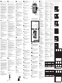 1
1
-
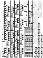 2
2


Documenti correlati
-
Socomec COUNTIS E5x Istruzioni per l'uso
-
-
-
-
Socomec DIRIS A60 Quick Start
-
-
-
-
-