GCE DGM-SK02/SK04/SK06/SK10 Istruzioni per l'uso
- Tipo
- Istruzioni per l'uso

DGMSK02/SK04/SK06/SK10
GAS MONITORING DEVICE EN
DISPOSITIVO DI MONITORAGGIO DEI GAS IT
INSTRUCTION FOR USE
ISTRUZIONI PER L‘USO
GCE CENTRAL GAS SYSTEMS

2/36
EN
1. SAFETY INDICATION
The gas monitoring device is a controlling system, which is designed for controlling individual
gas cylinders and multiple cylinder bundles. The gas monitoring device is constructed to be
reliable in service according to the technical standard and takes the standardised rules and
EC-guidelines into consideration.
Improper installation or use can lead to malfunction and safety risks, for example no signalling
of the minimum level caused by wrong connection of the signalling terminals.
Installation, electrical connection, start-up, service and upkeep of the controlling equipment
should only be carried out by trained persons, who are authorised to do so.
These service instructions must be read completely before installation. If described devices are
used for an Ex range than the corresponding national norms have to be observed.
Especially, we point out the following rules, supplementing documentations that are required
or used to a limited degree.
• Directive 2014/34/EU
• Directive 2014/35/EU
NOTE: We reserve the right to make technical alterations which improve the product.
2. SAFETY RELEVANT INDICATION
Safety relevant activities and processes are stressed by symbols, although each indication is
marked through a corresponding pictogram.
SYMBOL MEANING
i
Indication!
This relates to an activity or processes, which can have a direct influence
on the operation of the unit if carried out in correctly
( i.e. will cause the instrument to malfunction).
Warning!
This relates to an activity or process which can lead to a hazardous situation
with danger of personal injury, to a safety risk or to the destruction of the
instrument, if carried out incorrectly.
2.1. CORRECT USE
The gas monitoring device is used for checking the minimum level of the gas cylinder station. If
a fall below of the minimum level of the gas cylinder is recognized, this will be indicated to the
user by optical and acoustic signals at the instrument. Signalling contact manometers with reed
or inductive contacts are used.
2.2. WRONG USE
All applications out of the described application possibilities in point 3 are not recommended
and can lead to risks and damages.
ENGLISH
INSTRUCTION FOR USE: GAS MONITORING DEVICE

3/36
EN
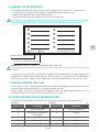
3. GENERAL OPERATING INDICATIONS
The gas monitoring device processes two, four, six, ten input channels that allow the connection
to contact gauges.
The connected sensors have to signal the fall below of the desired operating pressure by
opening the contact.
The contact voltage, delivered from the signal box is 6V/DC at a maximum current of 10mA a
“emergency response“ is shown as follows:
a) If minimum pressure falls below:
• corresponding display flashes and the alarm sounds
• After acknowledgement with the reset button the alarm goes o.
And the signal-LED turns from the flashing mode to the continuous mode The signal-LED only
goes out if the fault has been removed ( i.e. gas cylinder has been changed)
b) A report comes up (already accepted) and a second report will be added:
• The already accepted error will be shown by a steady light emission of the corresponding LED
• After activation of the reset button the horn sound goes out and the flashing frequency will
switch o.
• (permanent on or permanent o, according to the condition of the gas pressure)
Additional to the optical displays on the signal box two potential relay contacts are available:
• The first relay contact is closed as long as the horn sound is existing (alarm is acceptable)
• The second relay contact closes, as soon as there is a fault and will only open if all fault
responses are removed. (collected alarm not acceptable)
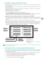
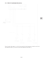
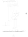
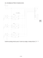
Betrieb Quitt Gasmangelwarnsystem
Supply 220-250V
/ 50-60Hz
Line to contact gauges
Leer Gasart Leer Gasart
Leer = Empty
Gasart = Type of gas
Betrieb = Operation
Quitt = Quit
Gasmangelwarnsystem = Gas-deficient
warning system
Gas Nr. 1
Gas Nr. 3
Operation - LED
Reset Button
Gas Nr. 4
Gas Nr. 1
Both contacts are only suitable for a maximum voltage of < 1A. The maximum mains lead is
running at 250VA / 65W.
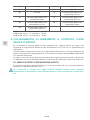
4. INSTALLATION OF THE GAS MONITORING DEVICE
The housing of the gas monitoring device is designed for wall installation. For this purpose four
fastening holes are positioned in the back housing part. These are accessed by removing the
cover. Removal is as follows:
1. with the help of a small screwdriver the cover strip has to strip from the cap to the front.
2. open the reachable screws (4 items) with the help of a cross screwdriver.
3. the cap is loose now and the under part is connected with a flat ribbon cable.
4. pull out the flat ribbon from the plug connection.
5. the fastening holes are now freely accessible.

4/36
EN
After mounting it is important to pay attention that the plug connection will re-plug the right way.
The assembly of the instrument is the reverse of the above instructions.
Indication, the pull out of the plug connection is only allowed in the dead condition.
The instrument is only allowed to be opened in a non-live condition by special trained sta.
5. STARTUP OF THE GAS MONITORING DEVICE
• The inputs of the gas monitoring device can be accessed over the MORSETTO strip in the
instrument (see enclosed diagram).
• The electrical connection of the gas monitoring device requires a direct supply 220-250 V /
50-60Hz (see diagram).
• The instrument is ready for operation after connection of the lead and contact gauges.
• After oering the working voltage 220-250 V / 110 V - 50-60Hz, a lamp check needs to be
executed.
• All LED’s are driven one after the other.
• The lamp check will be finished with the acoustical horn sound of the alarm buzzer.
• If there are no empty reports at the instrument, a new lamp check or instrument check can be
executed by activity of the reset button (as described before)
Work on electrical connections must only be made by special trained sta. According to VDE
the instrument has to be disconnected before opening.
6. TAKING OUT OF OPERATION
For taking out the gas monitoring device the following points have to be observed.
• Before opening it is important to disconnect the instrument from the mains voltage
• clamp the lines of the signal instrument
• now, the instrument can be taken down
Work on electrical connections are only allowed to be made by special trained sta. Accord-
ing to VDE the instrument has to be disconnected before opening.
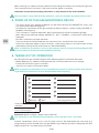
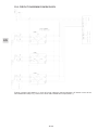
Betrieb Quitt Gasmangelwarnsystem
Leer Gasart Leer Gasart
Supply 220-250V
/ 50-60Hz
Line to contact gauges
Dimension (width x height x depth): 200 x 120 x 60
The signal box is not allowed to be positioned in the hazardous area ( Ex-range!)
Contact manometers which are in the Ex-range have to be decoupled with the help of a
disconnecting switch amplifier from the gas defect signal device! (inherent safety).look for VDE
0165 and point 11 in this operating instruction.

5/36
EN
7. CABLE INTRODUCTION
The cables required for the connection of the gas monitoring device can be introduced in the
back part with the help of cable adapters.
For this, in the back part of the housing break out openings are positioned in which a maximum
of four cable adapters PG11 can be fixed on.
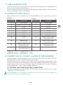
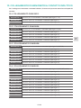
8. MORSETTO STRIP LAYOUT
The instrument will be connected over the fixed MORSETTO strip in the under part of the
housing.
Example DGM-SK 10:
MORSETTO FUNCTION MORSETTO FUNCTION
1phase (lead) 2neutral (lead)
3protective conductor (lead) 4+ 6 VDC
5canale 1 6canale 2
7canale 3 8canale 4
9canale 5 10 canale 6
11 canale 7 12 canale 8
13 canale 9 14 canale 10
15 screen 16 potential free contact
(acceptable) closer
17 potential free
contact(acceptable) root
18 potential free contact
(acceptable) opener
19 potential free contact
(acceptable) closer
20 potential free contact
(acceptable) root
21 potential free contact
(acceptable) opener
DGM-SK 02: canale 1 and 2, MORSETTO 7 – 14: NC
DGM-SK 04: canale 1 – 4, MORSETTO 9 – 14: NC
DGM-SK 06: canale 1 – 6, MORSETTO 11 – 14: NC
9. CONNECTION OF CONTACT GAUGES IN THE EXRANGE
If contact gauges shall be connected in the ex-range, the inputs of the signal box have to be
decoupled with the help of a disconnecting switch amplifier.
The disconnecting switch amplifier transfers digital signals of the explosion-endangered range.
The inputs are put out for the connection of a sensor after NAMUR or DIN 19234 or a mechanical
contact. Inputs, outputs and supply voltage are galvanic separated from each other according
to DIN VDE0160 for a rated insulation voltage of 250V AC.
9.1. SUITABLE DISCONNECTING SWITCH AMPLIFIER:
The technical department of the company GCE will find the suitable version for you. In case of
need contact GCE representative.
If contact gauges in the ex-range are operated without disconnecting switch amplifier, this
could lead to hazardous and explosion risks.

6/36
EN
10. CONNECTION OF INDUCTIVE CONTACT GAUGES
If you connect an inductive contact gauge you have to pay attention to the right polarity.
10.1. CONNECTION DGMSK02:
MORSETTO 4 plus at the contact manometer (gas type 1 u. 2)
MORSETTO 5 minus at the contact manometer (gas type 1)
MORSETTO 6 minus at the contact manometer ( gas type 2)
10.2. CONNECTION DGMSK04:
MORSETTO 4 plus at the contact manometer (gas type 1;2;3;4)
MORSETTO 5 minus at the contact manometer (gas type 1)
MORSETTO 6 minus at the contact manometer ( gas type 2)
MORSETTO 7 minus at the contact manometer (gas type 3)
MORSETTO 8 minus at the contact manometer (gas type 4)
10.3. CONNECTION DGMSK06:
MORSETTO 4 plus at the contact manometer (gas type 1;2;3;4;5;6)
MORSETTO 5 minus at the contact manometer (gas type 1)
MORSETTO 6 minus at the contact manometer ( gas type 2)
MORSETTO 7 minus at the contact manometer (gas type 3)
MORSETTO 8 minus at the contact manometer (gas type 4)
MORSETTO 9 minus at the contact manometer (gas type 5)
MORSETTO 10 minus at the contact manometer (gas type 6)
10.4. CONNECTION DGMSK10:
MORSETTO 4 plus at the contact manometer (gas type 1;2;3;4;5;6;7;8;9;10)
MORSETTO 5 minus at the contact manometer (gas type 1)
MORSETTO 6 minus at the contact manometer ( gas type 2)
MORSETTO 7 minus at the contact manometer (gas type 3)
MORSETTO 8 minus at the contact manometer (gas type 4)
MORSETTO 9 minus at the contact manometer (gas type 5)
MORSETTO 10 minus at the contact manometer (gas type 6)
MORSETTO 11 minus at the contact manometer (gas type 7)
MORSETTO 12 minus at the contact manometer (gas type 8)
MORSETTO 13 minus at the contact manometer (gas type 9)
MORSETTO 14 minus at the contact manometer (gas type 10)

7/36
EN
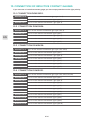
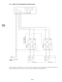
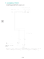
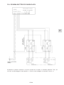
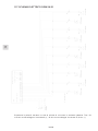
11. CIRCUIT DIAGRAM
11.1. CIRCUIT DIAGRAM DGM SK 02
Please respect right polarity in case of using inductive contact gauges. All brown wires to be
connected to clamp 4 (+), blue wires to be connected to clamp 5,6 etc. (-).

8/36
EN
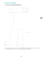
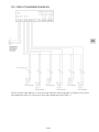
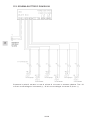
11.2. CIRCUIT DIAGRAM DGM SK02 EX
Please respect right polarity in case of using inductive contact gauges. All brown wires to be
connected to clamp 4 (+), blue wires to be connected to clamp 5,6 etc. (-).

9/36
EN
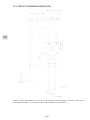
11.3. CIRCUIT DIAGRAM DGM SK04
Please respect right polarity in case of using inductive contact gauges. All brown wires to be
connected to clamp 4 (+), blue wires to be connected to clamp 5,6 etc. (-).

10/36
EN
11.4. CIRCUIT DIAGRAM DGM SK04 EX
Please respect right polarity in case of using inductive contact gauges. All brown wires to be
connected to clamp 4 (+), blue wires to be connected to clamp 5,6 etc. (-).

11/36
EN
11.5. CIRCUIT DIAGRAM DGM SK06
Please respect right polarity in case of using inductive contact gauges. All brown wires to be
connected to clamp 4 (+), blue wires to be connected to clamp 5,6 etc. (-).

12/36
EN
11.6. CIRCUIT DIAGRAM DGM SK06 EX
Please respect right polarity in case of using inductive contact gauges. All brown wires to be
connected to clamp 4 (+), blue wires to be connected to clamp 5,6 etc. (-).

13/36
EN
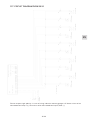
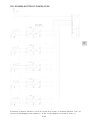
11.7. CIRCUIT DIAGRAM DGM SK10
Please respect right polarity in case of using inductive contact gauges. All brown wires to be
connected to clamp 4 (+), blue wires to be connected to clamp 5,6 etc. (-).

14/36
EN
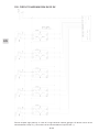
11.8. CIRCUIT DIAGRAM DGM SK10 EX
Please respect right polarity in case of using inductive contact gauges. All brown wires to be
connected to clamp 4 (+), blue wires to be connected to clamp 5,6 etc. (-).

15/36
EN
12. SERVICE AND REPAIR
In principle, the instrument is free of service. If you find instrument defects, send the instrument
for repair to the manufacturer.
For this purpose observe the points in paragraph „taking out of operation“
Electrical connection works are only allowed to be made by special trained sta. According to
VDE the instrument has to be disconnected before opening.
13. WASTE MANAGEMENT
In accordance to Article 33 of REACH GCE, s.r.o. as responsible manufacturer shall inform all
customers if materials containing 0.1% or more of substances included in the list of Substance
of Very High Concern (SVHC).
The most commonly used brass alloys used for bodies and other brass components contain
2-3% of lead (Pb), EC no. 231-468-6, CAS no. 7439-92-1. The lead will not be released to the gas
or surrounding environment during normal use. After end of life the product shall be scrapped
by an authorized metal recycler to ensure ecient material handling with minimal impact to
environment and health.
To date we have no information that indicates that other materials containing SVHC of
concentrations exceeding 0.1% are included in any GCE product.

16/36
EN
14. TECHNICAL DATA
CONNECTION VALUE
Power supply 220-250V AC. 50 Hz, 5 VA
Fuse 315 mA carrier
i Defect fuses are only allowed to be replaced by the
manufacturer.
INPUTS
Signalling potential free, mechanic contacts according to DIn 19234
(NAMUR)
Eective direction NC (see Chapter 3)
Connection technique 2 wire
Supply of the signalling 10 V Max. through the instrument, 10mA Max. (short-circuit
proof)
OUTPUT COLLECTED ALARM
Alarm output 2* relay output (1 changing contact)
Max. contact load AC 230 V -, 50 Hz, 100 VA
Max. contact load DC 48 V, 1A
Buzzer 85 dB/0,1 m, 2,3 khz
INTERN ALARM EQUIPMENT
Luminous alarm LED red, green 5 mm Ø
Acoustic alarm signalling device, f = 3,3 kHz
ENVIROMENT CONDITIONS
Environment temperature 40° C - C Max.
Humidity 0 - 95% relative humidity, not condensated
EXECUTION
Housing polystyrene, colour similar to RAL 7035 (grey)
Protection type IP 54
Dimension 200 x 160 x 60 mm (w x h x d)
Installation position upright, out of ex-range
Connection cross-section 2,5 mm2 Max.
Cable screws 4 items PG11

17/36
EN
APPENDIX:
CE-conformity explanation
PTB-certificate for disconnecting switch amplifier
MANUFACTURER:
GCE, s.r.o. Tel : +420 569 661 111
Zizkova 381 Fax : +420 569 661 602
583 01 Chotebor http://www.gcegroup.com
Czech Republic © GCE, s.r.o

18/36
IT
1. INDICAZIONI DI SICUREZZA
Il dispositivo di monitoraggio dei gas è un sistema di controllo progettato per controllare
singole bombole di gas e gruppi di bombole multiple. Il dispositivo di monitoraggio dei gas è
stato realizzato per garantire un funzionamento adabile in conformità alle norme tecniche e
prende in considerazione le norme standardizzate e le linee guida CE.
Un’installazione o un uso improprio possono comportare malfunzionamenti e rischi per
la sicurezza, ad esempio l’assenza di segnalazione del livello minimo causato da un errato
collegamento dei terminali di segnalazione.
L’installazione, il collegamento elettrico, l’avviamento, la manutenzione e l’assistenza per le
apparecchiature di controllo devono essere eseguiti esclusivamente da personale addestrato
e autorizzato.
Le presenti istruzioni per l’uso devono essere lette completamente prima dell’installazione.
Se i dispositivi descritti vengono utilizzati per un intervallo diverso, è necessario rispettare le
corrispondenti norme nazionali. In particolare, segnaliamo le seguenti regole, che integrano le
documentazioni che sono richieste o utilizzate in misura limitata.
• Direttiva 2014/34/EU
• Direttiva 2014/35/EU
NOTa: Ci riserviamo il diritto di apportare modifiche tecniche che migliorino il prodotto.
2. INDICAZIONI RELATIVE ALLA SICUREZZA
Le attività e i processi rilevanti per la sicurezza sono indicati da simboli, sebbene ciascuna
indicazione sia contrassegnata da un pittogramma corrispondente.
SIMBOLO SIGNIFICATO
i
Indicazione!
Ciò si riferisce a un’attività o a processi che possono avere un’influenza
diretta sul funzionamento
dell’unità se non eseguiti correttamente (ciò causerà il malfunzionamento
del dispositivo).
Attenzione!
Ciò si riferisce a un’attività o a un processo che può portare a una situazione
pericolosa con rischio di lesioni personali, rischio per la sicurezza o distruzi-
one del dispositivo, se non eseguito correttamente.
2.1. USO CORRETTO
Il dispositivo di monitoraggio dei gas viene utilizzato per controllare il livello minimo della
centrale delle bombole di gas. Se viene riconosciuto un calo al di sotto del livello minimo della
bombola di gas, ciò verrà segnalato all’utilizzatore tramite segnali visivi e acustici sul dispositivo.
Vengono utilizzati manometri di contatto di segnalazione con contatti reed o induttivi.
2.2. USO ERRATO
Tutte le applicazioni che non rientrano in quelle possibili descritte al punto 3 non sono
raccomandate e possono comportare rischi e danni.
ITALIANO
ISTRUZIONI PER L‘USO: DISPOSITIVO DI MONITORAGGIO DEI GAS

19/36
IT
3. INDICAZIONI GENERALI DI FUNZIONAMENTO
Il dispositivo di monitoraggio dei gas opera tramite due canali di ingresso che consentono il
collegamento di due manometri a contatto.
I sensori collegati devono segnalare il calo al di sotto della pressione di esercizio desiderata
aprendo il contatto.
La tensione di contatto erogata dal dispositivo di segnalazione è di 6 V/CC a una corrente
massima di 10 mA; una “risposta di emergenza” viene mostrata come segue:
a) Se la pressione minima scende al di sotto di:
• il display corrispondente lampeggia e viene emesso un segnale acustico di allarme
• Dopo aver ricevuto la conferma con il tasto QUIT, l’allarme si spegne. E il LED del segnale
passa dalla modalità lampeggiante a quella continua. Il LED del segnale si spegne solo se il
guasto è stato rimosso (ad esempio, la bombola del gas è stata sostituita)
b) Viene segnalato un errore (già accettato) e viene aggiunta una seconda segnalazione:
• L’errore già accettato viene indicato con la luce fissa del corrispondente LED
• Dopo l’attivazione del tasto QUIT, il suono dell’avvisatore acustico si spegne e il
lampeggiamento si spegne.
• (accensione permanente o spegnimento permanente, a seconda delle condizioni della
pressione del gas)
Oltre ai segnali visivi sul dispositivo di segnalazione, sono disponibili due contatti relè
potenziali:
• Il primo contatto relè viene chiuso mentre il suono dell’avvisatore acustico è presente
(l’allarme è accettabile)
• Il secondo contatto relè si chiude non appena si verifica un guasto e si apre solo se tutti i
guasti sono stati rimossi. (allarme individuato non accettabile)
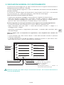
Betrieb Quitt Gasmangelwarnsystem
Alimentazione 230 V/50 Hz
Da linea a indicatori di contatto
Leer Gasart Leer Gasart
Leer = vuoto
Gasart = tipo di gas Betrieb
Betrieb = operazione
Quitt = conferma
Gasmangelwarnsystem = sistema di
avvertimento mancanza di gas
Gas Nr. 1
Gas Nr. 3
Funzionamento LED - LED
Conferma (QUIT)
Gas Nr. 4
Gas Nr. 1
Entrambi i contatti sono adatti solo per una tensione massima < 1 A. Il cavo di rete funziona a
massimo 250 VA/65 W.

20/36
IT
4. INSTALLAZIONE DEL DISPOSITIVO DI MONITORAGGIO DEI
GAS
L’alloggiamento del dispositivo di monitoraggio dei gas è progettato per l’installazione a parete.
A tale scopo, quattro fori di fissaggio sono posizionati nella parte posteriore dell’alloggiamento.
È possibile accedervi rimuovendo il coperchio. La rimozione si esegue nel modo seguente:
1. con l’aiuto di un piccolo cacciavite, la striscia di copertura deve essere estratta dalla
copertura verso la parte anteriore.
2. svitare le 4 viti con l’ausilio di un cacciavite a croce.
3. la copertura è allentata e la parte inferiore è collegata con un cavo a nastro piatto.
4. estrarre il cavo a nastro piatto dal collegamento a spina.
5. i fori di fissaggio sono ora liberamente accessibili.
Dopo il montaggio, è importante prestare attenzione al fatto che il collegamento a spina si
reinserisca nel modo corretto.
Per il montaggio del dispositivo, seguire la procedura inversa.
Indicazione: l’estrazione del collegamento a spina è consentita solo se spento.
L’apertura del dispositivo va eseguita solo se non è sotto tensione e da parte di personale
specializzato.
5. AVVIAMENTO DEL DISPOSITIVO DI MONITORAGGIO DEI
GAS
• È possibile accedere agli ingressi del dispositivo di monitoraggio dei gas dalla morsettiera del
dispositivo (vedere lo schema allegato).
• Il collegamento elettrico del dispositivo di monitoraggio dei gas richiede un’alimentazione
diretta di 230 V / 110 V - 50 Hz (vedere lo schema).
• Il dispositivo è pronto al funzionamento dopo il collegamento del cavo di rete e dei manometri
a contatto.
• Una volta alimentato il dispositivo con una tensione di esercizio di 230 V / 110 V - 50 Hz, è
necessario eseguire un controllo delle spie.
• Tutti i LED vengono azionati uno dopo l’altro.
• Il completamento del controllo delle spie viene segnalato dal cicalino di allarme.
• Se sono presenti segnalazioni sul dispositivo, è possibile eseguire un nuovo controllo delle
spie o un controllo del dispositivo tramite il tasto QUIT (come descritto in precedenza).
Gli interventi sui collegamenti elettrici devono essere eseguiti esclusivamente da personale
specializzato. Secondo le norme VDE, il dispositivo deve essere scollegato prima dell’apertura.
La pagina si sta caricando...
La pagina si sta caricando...
La pagina si sta caricando...
La pagina si sta caricando...
La pagina si sta caricando...
La pagina si sta caricando...
La pagina si sta caricando...
La pagina si sta caricando...
La pagina si sta caricando...
La pagina si sta caricando...
La pagina si sta caricando...
La pagina si sta caricando...
La pagina si sta caricando...
La pagina si sta caricando...
La pagina si sta caricando...
La pagina si sta caricando...
-
 1
1
-
 2
2
-
 3
3
-
 4
4
-
 5
5
-
 6
6
-
 7
7
-
 8
8
-
 9
9
-
 10
10
-
 11
11
-
 12
12
-
 13
13
-
 14
14
-
 15
15
-
 16
16
-
 17
17
-
 18
18
-
 19
19
-
 20
20
-
 21
21
-
 22
22
-
 23
23
-
 24
24
-
 25
25
-
 26
26
-
 27
27
-
 28
28
-
 29
29
-
 30
30
-
 31
31
-
 32
32
-
 33
33
-
 34
34
-
 35
35
-
 36
36


GCE DGM-SK02/SK04/SK06/SK10 Istruzioni per l'uso
- Tipo
- Istruzioni per l'uso
in altre lingue
Documenti correlati
Altri documenti
-
Rothenberger Nitrogen set for refrigeration circuits Manuale utente
-
-
WIKA A2G-30 Istruzioni per l'uso
-
Carel Cabinet 230 l/h Manuale utente
-
-
Maserati Ghibli Manuale del proprietario
-
JBL ProFlora u402 Instructions For Use Manual
-
ProMinent S3Cb Operating Instructions Manual
-
MasterCool 53050 Istruzioni per l'uso
-
ESAB M3® Plasma Precision Plasmarc Plasma Gas Box & Shield Gas Box Manuale utente