ProMinent S3Cb Operating Instructions Manual
- Categoria
- Attrezzatura per ossigeno
- Tipo
- Operating Instructions Manual
Questo manuale è adatto anche per

Diaphragm Motor-Driven Metering Pump
Sigma X Control type — Sigma/ 3 - S3Cb
Operating instructions
EN
Original operating instructions (2006/42/EC)Part no. 982514 BA SI 080 07/18 EN
Please carefully read these operating instructions before use. · Do not discard.
The operator shall be liable for any damage caused by installation or operating errors.
The latest version of the operating instructions are available on our homepage.

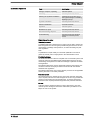
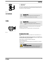
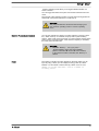
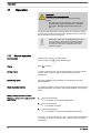
Read the following supplementary information in its entirety! Should you
already know this information, you will benefit more from referring to the
operating instructions.
The following are highlighted separately in the document:
n Enumerated lists
Handling instructions
ð
Outcome of the operation guidelines
- see (reference)
Information
This provides important information relating to the cor‐
rect operation of the device or is intended to make your
work easier.
Safety notes
Safety notes are identified by pictograms - see Safety Chapter.
At the time of going to press, these operating instructions conformed to the
current EU regulations.
Please state identity code and serial number, which you can find on the
nameplate when you contact us or order spare parts. This enables the
device type and material versions to be clearly identified.
Supplementary information
Fig. 1: Please read!
Validity
State the identity code and serial number
Supplemental directives
2

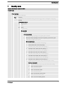
Table of contents
1
Identity code.................................................................................... 5
2 Safety Chapter................................................................................. 8
3 Storage, Transport and Unpacking................................................ 12
4 Overview of equipment and control elements............................... 13
4.1 Control elements................................................................... 15
4.2 Key functions......................................................................... 17
5 Functional description.................................................................... 18
5.1 Pump..................................................................................... 18
5.2 Liquid end.............................................................................. 19
5.3 Bleed valve and integrated relief valve ................................ 19
5.4 Multi-layer safety diaphragm................................................. 20
5.5 Operating modes................................................................... 20
5.6 Functions............................................................................... 21
5.7 Options.................................................................................. 22
5.8 Function and fault indicator................................................... 22
5.8.1 LCD screen........................................................................ 22
5.8.2 LED displays...................................................................... 23
5.9 Hierarchy of operating modes, functions and fault sta‐
tuses......................................................................................
23
6 Assembly....................................................................................... 24
7 Installation..................................................................................... 26
7.1 Installation, hydraulic............................................................. 26
7.1.1 Basic installation notes....................................................... 30
7.2 Installation, electrical............................................................. 31
7.2.1 Control connectors............................................................. 32
7.2.2 HMI operating unit.............................................................. 39
7.2.3 Pump, power supply........................................................... 40
7.2.4 Other units.......................................................................... 41
8 Basic set-up principles................................................................... 42
8.1 Basic principles for setting up the control.............................. 42
8.2 Checking adjustable variables.............................................. 44
8.3 Changing to Setting mode..................................................... 44
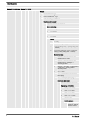
9 Set up /
‘Menu’
.............................................................................. 45
9.1
‘Information’
......................................................................... 45
9.2
‘Operating mode’
.................................................................. 45
9.3
‘Settings’
.............................................................................. 45
9.3.1
‘Operating mode’
............................................................... 46
9.3.2
‘Metering’
.......................................................................... 50
9.3.3
‘Calibration’
....................................................................... 51
9.3.4
‘Inputs/outputs’
.................................................................. 53
9.3.5
‘System’
............................................................................ 55
9.3.6
‘Set time’
........................................................................... 56
9.3.7
‘Date’
................................................................................. 56
9.4
‘Timer’
.................................................................................. 56
9.4.1 Timer
‘activation’
............................................................... 56
9.4.2
‘Setting the timer’
.............................................................. 56
9.4.3
‘Clear all’
........................................................................... 58
9.4.4 Example............................................................................. 59
9.5
‘Service’
............................................................................... 59
9.5.1
‘Password’
......................................................................... 59
9.5.2
‘Clear counter’
................................................................... 59
9.5.3
‘Log book’
.......................................................................... 60
Table of contents
3

9.5.4
‘Display’
............................................................................. 60
9.5.5
‘HMI logout’
....................................................................... 60
9.5.6
‘Diaphragm part number: XXXXXXX’
................................ 60
9.5.7
‘Spare parts kit part number: XXXXXXX’
.......................... 61
9.6
‘Language’
........................................................................... 61
10 Start up.......................................................................................... 62
11
Operation....................................................................................... 66
11.1 Manual operation................................................................ 66
12 Maintenance.................................................................................. 68
13 Carrying out repairs....................................................................... 71
13.1 Cleaning valves................................................................... 71
13.2 Replacing the diaphragm.................................................... 73
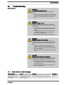
14 Troubleshooting............................................................................. 77
14.1 Faults without a fault message............................................ 77
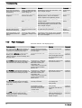
14.2 Fault messages................................................................... 78
14.3 Warning messages............................................................. 79
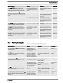
14.4 All other faults..................................................................... 80
14.5 Log book............................................................................. 80
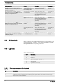
14.5.1 Warning messages in the log book.................................. 80
14.5.2 Fault messages in the log book....................................... 81
14.5.3 Events in the log book...................................................... 82
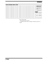
15 Decommissioning.......................................................................... 83
16 Technical data............................................................................... 86
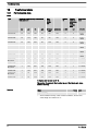
16.1 Performance data................................................................ 86
16.2 Viscosity.............................................................................. 87
16.3 Shipping weight................................................................... 87
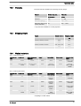
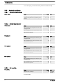
16.4 Wetted materials................................................................. 87
16.5 Ambient conditions.............................................................. 88
16.5.1 Ambient temperatures...................................................... 88
16.5.2 Media temperatures......................................................... 88
16.5.3 Air humidity...................................................................... 88
16.5.4 Degree of Protection and Safety Requirements............... 89
16.6 Installation height................................................................ 89
16.7 Electrical connection........................................................... 89
16.8 Diaphragm rupture sensor.................................................. 90
16.9 Relay................................................................................... 90
16.10 Gear oil.............................................................................. 91
16.11 Sound pressure level........................................................ 91
17 Dimensional drawings................................................................... 92
18
Motor data sheets.......................................................................... 95
19 Liquid ends for Sigma/ 3................................................................ 96
20 Wear parts for S3Cb.................................................................... 106
20.1 Standard............................................................................ 106
20.2 Physiological safety........................................................... 106
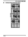
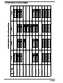
21 Diagrams for adjusting the capacity............................................ 108
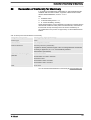
22
Declaration of Conformity for Machinery..................................... 109
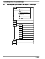
23 Operating/Set-up overview of the Sigma X Control type............. 110
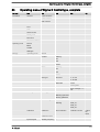
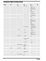
24 Operating menu of Sigma X Control type, complete................... 111
25 Continuous displays and secondary displays.............................. 115
26 Index............................................................................................ 117
Table of contents
4

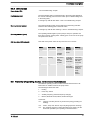
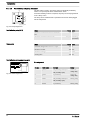
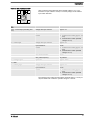
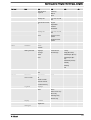
1 Identity code
Sigma X Control type - Sigma/ 3 - S3Cb
Product range
S3Cb
Power end type
H Main power end, diaphragm
Type Capacity
_ _ _ _ _
_
Performance data at maximum back pressure and type: refer to nameplate on the pump
housing
Dosing head material
PP Polypropylene
PC PVC
PV PVDF
SS Stainless steel
Seal material
T PTFE
Displacement body
S Multi-layer safety diaphragm with optical rupture indicator
A Multi-layer safety diaphragm with rupture signalling by electrical signal
H Diaphragm for hygienic pump head
Dosing head design
0 without bleed valve, without valve springs
1 without bleed valve, with valve springs
2 with bleed valve, FPM, without valve springs ***
3 with bleed valve, FPM, with valve springs ***
4 with relief valve, FPM, without valve springs ***
5 with relief valve, FPM, with valve springs ***
6 with relief valve, EPDM, without valve springs ***
7 with relief valve, EPDM, with valve springs ***
8 with bleed valve, EPDM, without valve springs ***
9 with bleed valve, EPDM, with valve springs ***
H Hygienic pump head with tri-clamp connectors (max. 10 bar)
Hydraulic connector
0 Standard threaded connector (in line with technical data)
1 Union nut and PVC insert
2 Union nut and PP insert
3 Union nut and PVDF insert
4 Union nut and SS insert
7 Union nut and PVDF hose nozzle
8 Union nut and SS hose nozzle
9 Union nut and SS welding sleeve
Identity code
5

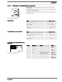
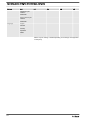
Sigma X Control type - Sigma/ 3 - S3Cb
Design
0
with ProMinent
®
logo
1
without ProMinent
®
logo
N Seal according to NEMA 4x
Electric power supply
U 1-phase, 100-240 V, 50/60 Hz
Cable and plug
A 2 m European
B 2 m Swiss
C 2 m Australian
D 2 m USA
Relay
0 no relay
1 Fault indicating relay (230V - 8A)
3 Fault indicating relay + pacing relay (24V
- 100mA)
8 0/4-20 mA analogue output + fault indi‐
cating / pacing relay (24V - 100mA)
Control version
0 Manual + external contact with
PulseControl + timer
1 Manual + external contact with
PulseControl + analogue +
metering profiles
2 Manual + controller + PulseControl
+ analogue + dosing profile +
extreme profile
5 as 1 + timer
6
as 1 + PROFIBUS
®
DP interface
(M12 plug)
7 as 1 + CANopen (M12 plug) **
Overload shut-down
0 without overload shut-down
Operating unit (HMI)
0 HMI (0.5 m cable)
4 HMI + 2 m cable
5 HMI + 5 m cable
6 HMI + 10 m cable
X without HMI
Safety options
0 Metering monitor,
dynamic, without
access control
Identity code
6

Sigma X Control type - Sigma/ 3 - S3Cb
1 Metering monitor,
dynamic, with
access control
B HMI with Blue‐
tooth
W HMI with Wi-Fi
Language
DE German
EN English
ES Spanish
FR French
FPM = fluorine rubber
** Pump without HMI control unit
*** Standard with tube nozzle in the bypass. Threaded connection on
request.
Identity code
7

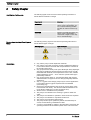
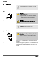
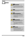
2 Safety Chapter
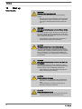
The following signal words are used in these operating instructions to
denote different severities of danger:
Signal word Meaning
WARNING Denotes a possibly dangerous sit‐
uation. If this is disregarded, you
are in a life-threatening situation
and this can result in serious inju‐
ries.
CAUTION Denotes a possibly dangerous sit‐
uation. If this is disregarded, it
could result in slight or minor inju‐
ries or material damage.
The following warning signs are used in these operating instructions to
denote different types of danger:
Warning signs Type of danger
Warning – high-voltage.
Warning – danger zone.
n Only use the pump to meter liquid feed chemicals.
n Only use the pump after it has been correctly installed and started up
in accordance with the technical data and specifications contained in
the operating instructions.
n Only pumps with the identity code option "Multi-layer safety diaphragm
with rupture signalling by electrical signal" are approved for use with
flammable feed chemicals, at back pressures of over 2 bar, software
setting
‘Diaphragm rupture’
-
‘Error’
and if the operator takes appro‐
priate safety measures.
n Only pumps with the design "F - Physiological safety with regard to
wetted materials" are approved for use with physiologically harmless
applications.
n Only “H - Hygienic head” design pumps may be used for applications
in accordance with the hygienic requirements of the EHEDG
(www.ededg.org).
n Observe the general limitations with regard to viscosity limits, chem‐
ical resistance and density - see also the ProMinent Resistance List
(in the Product Catalogue or at www.prominent.com)!
n All other uses or modifications are prohibited.
n The pump is not intended for the metering of gaseous media and
solids.
n The pump is not intended for operation in areas at risk from explosion.
n The pump is not intended for unprotected outside use.
n The pump is only intended for industrial use.
n The pump should only be operated by trained and authorised per‐
sonnel, see the following "Qualifications" table.
n You have a responsibility to adhere to the information contained in the
operating instructions at the different phases of the unit's service life.
Identification of safety notes
Warning signs denoting different types of
danger
Intended use
Safety Chapter
8

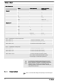
Task Qualification
Storage, transport, unpacking Instructed person
Assembly Technical personnel, Service
Planning the hydraulic installation Qualified personnel who have a
thorough knowledge of oscillating
diaphragm pumps.
Hydraulic installation Technical personnel, Service
Electrical Installation Electrical technician
Operation Instructed person
Maintenance, repair Technical personnel, Service
Decommissioning, disposal Technical personnel, Service
Troubleshooting Technical personnel, electrical
technician, instructed person,
service
Explanation of the table:
Technical personnel
A qualified employee is deemed to be a person who is able to assess the
tasks assigned to him and recognise possible dangers based on his tech‐
nical training, knowledge and experience, as well as knowledge of perti‐
nent regulations.
Note:
A qualification of equal validity to a technical qualification can also be
gained by several years of employment in the relevant field of work.
Electrical technician
An electrical technician is able to complete work on electrical systems and
recognise and avoid possible dangers independently based on his tech‐
nical training and experience as well as knowledge of pertinent standards
and regulations.
The electrical technician must be specifically trained for the working envi‐
ronment in which he is employed and be conversant with the relevant
standards and regulations.
The electrical technician must comply with the provisions of the applicable
statutory directives on accident prevention.
Instructed person
An instructed person is deemed to be a person who has been instructed
and, if required, trained in the tasks assigned to him and any possible dan‐
gers that could result from improper behaviour, as well as having been
instructed in the required protective equipment and protective measures.
Service
Customer Service department refers to service technicians, who have
received proven training and have been authorised by ProMinent or Pro‐
Maqua to work on the system.
Qualification of personnel
Safety Chapter
9

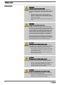
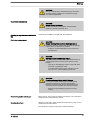
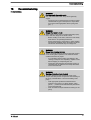
WARNING!
Warning of hazardous feed chemical
Should a dangerous feed chemical be used: it may
escape from the hydraulic components when working on
the pump, material failure or incorrect handling of the
pump.
– Take appropriate protective measures before
working on the pump (e.g. safety glasses, safety
gloves, ...). Adhere to the material safety data sheet
for the feed chemical.
–
Drain and flush the liquid end before working on the
pump.
WARNING!
Danger from hazardous substances!
Possible consequence: Fatal or very serious injuries.
Please ensure when handling hazardous substances
that you have read the latest safety data sheets provided
by the manufacture of the hazardous substance. The
actions required are described in the safety data sheet.
Check the safety data sheet regularly and replace, if
necessary, as the hazard potential of a substance can
be re-evaluated at any time based on new findings.
The system operator is responsible for ensuring that
these safety data sheets are available and that they are
kept up to date, as well as for producing an associated
hazard assessment for the workstations affected.
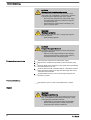
CAUTION!
Warning of feed chemical spraying around
Feed chemical can spray out of the hydraulic compo‐
nents if they are manipulated or opened due to pressure
in the liquid end and adjacent parts of the system.
– Disconnect the pump from the mains power supply
and ensure that it cannot be switched on again by
unauthorised persons.
–
Depressurise the system before commencing any
work on hydraulic parts.
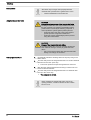
CAUTION!
Warning of feed chemical spraying around
An unsuitable feed chemical can damage the parts of
the pump that come into contact with the chemical.
– Take into account the resistance of the wetted mate‐
rials and the ProMinent Resistance List when
selecting the feed chemical - see the ProMinent
Product Catalogue or visit ProMinent.
CAUTION!
Danger of personnel injury and material damage
The use of untested third party parts can result in per‐
sonnel injuries and material damage.
– Only fit parts to metering pumps, which have been
tested and recommended by ProMinent.
Safety information
Safety Chapter
10

CAUTION!
Danger from incorrectly operated or inadequately main‐
tained pumps
Danger can arise from a poorly accessible pump due to
incorrect operation and poor maintenance.
– Ensure that the pump is accessible at all times.
–
Adhere to the maintenance intervals.
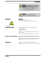
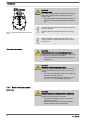
WARNING!
An on/off switch may not be fitted on the pump,
dependent on the identity code and installation.
Warning labels
This warning sign is affixed to the motor:
Ensure that the warning sign is always fitted and clearly visible.
All isolating protective equipment must be installed for operation:
n Drive front cover
n Motor fan cowling
n Motor terminal box cover
n Hood
In exactly the same way, plug all relays, modules and options into the
hood - if available.
Only remove them when the operating instructions request you to do so.
In the event of an electrical accident, disconnect the mains cable from the
mains or press the emergency cut-off switch fitted on the side of the
system!
If feed chemical escapes, also depressurise the hydraulic system around
the pump as necessary. Adhere to the safety data sheet for the feed
chemical.
Sound pressure level LpA < 70 dB according to EN ISO 20361
at maximum stroke length, maximum stroke rate, maximum back pressure
(water)
Safety equipment
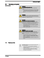
Fig. 2: Hot surface
Isolating protective equipment
Information in the event of an emergency
Sound pressure level
Safety Chapter
11

3 Storage, Transport and Unpacking
WARNING!
Only return the metering pump for repair in a cleaned
state and with a flushed liquid end - refer to the chapter
"Decommissioning"!
Only return metering pumps with a completed Decon‐
tamination Declaration form. The Decontamination Dec‐
laration constitutes an integral part of an inspection /
repair order. A unit can only be inspected or repaired
when a Declaration of Decontamination Form is sub‐
mitted that has been completed correctly and in full by
an authorised and qualified person on behalf of the
pump operator.
The "Decontamination Declaration Form" can be found
at www.prominent.com.
WARNING!
Slings can tear
ProMinent only supplies “non-reusable slings” in accord‐
ance with DIN EN 60005. They can tear with repeated
use.
– Destroy and remove the slings as soon as the pump
has been lifted into its final position.
CAUTION!
Danger of material damage
The device can be damaged by incorrect or improper
storage or transportation!
– The unit should only be stored or transported in a
well packaged state - preferably in its original pack‐
aging.
–
Only transport the unit when the red gear bleeding
plug is pushed in.
– The packaged unit should also only be stored or
transported in accordance with the stipulated
storage conditions.
– The packaged unit should be protected from mois‐
ture and the ingress of chemicals.
Compare the delivery note with the scope of supply:
Personnel:
n
Technical personnel
1. Plug the caps on the valves.
2. Check if the red gear bleeding plug is pushed in.
3. Preferably place the pump standing vertically on a pallet and secure
against falling over.
4. Cover the pump with a tarpaulin cover - allowing rear ventilation.
Store the pump in a dry, sealed place under the ambient conditions
according to chapter "Technical Data".
Safety information
Scope of delivery
Storage
Storage, Transport and Unpacking
12

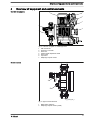
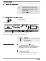
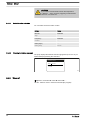
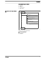
4 Overview of equipment and control elements
P_SI_0191_SW
1
2
5
6
7
3
4
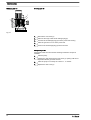
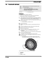
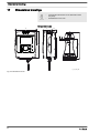
Fig. 3: Overview of Sigma X - S3Cb equipment
1 HMI control unit
2 Frequency converter
3 Drive unit
4 Stroke length adjustment wheel
5 Drive motor
6 Liquid end
7 Diaphragm rupture sensor
1
2
P_SI_0088_SW_2
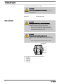
Fig. 4: Sigma control elements
1 Bleed valve (optional)
2 Diaphragm rupture sensor (visual)
Overview of equipment
Control elements
Overview of equipment and control elements
13

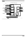
P_SI_0180_SW
3
1
5
4
2
10
9
8
6
7
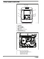
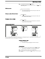
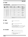
Fig. 5: Control elements for HMI Sigma X Control type
1 LCD screen
2
[Menu]
key
3
Clickwheel
4
[Priming]
key
5
[STOP/START]
key
6
[Back]
key
7 "Bluetooth active” display (blue)
8 Fault indicator (red)
9 Warning indicator (yellow)
10 Operating indicator (green)
P_SI_0193_SW
6
7
543
2
1
8
Fig. 6: Connector cover control elements
1 Relay and mA-output (option)
2
Slot for optional module (PROFIBUS
®
, ...)
3 "Diaphragm rupture" socket
4 "External control" terminal
5 "Metering monitor" terminal
Overview of equipment and control elements
14

6 "Level switch" terminal
7 "CAN bus" socket (external)
8 LEDs (as Fig. 5) and CAN bus status LED (external)
not shown Stroke length adjustment wheel
4.1 Control elements
Use this overview to familiarise yourself with the keys
and the other control elements on the pump!
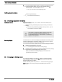
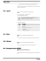
12012
12000
CONTACT
memory
l/h
CAN
open
hh
B1087
1
3
2
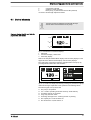
Fig. 7: Construction of continuous display
1 Status bar
2 Continuous display, central area
3 Secondary display
Refer to the chapter entitled "Main displays and secondary displays" in the
Appendix for the different main displays and secondary displays.
The LCD screen supports the operation and adjustment of the pump by
providing different information and identifiers:
120120
12000
Dosing monitor!
CONTACT
memory
l/h
CAN
open
hh
12000
ANALOGUE
hh
Input signal < 4 mAInput signal < 4 mA
i < 4 mAi < 4 mA
B1088
a)
b)
i < 4 mA!
Fig. 8: a) Continuous display with warning message; b) Continuous display
with fault message. Explanation of the symbols in the following tables.
The above Figure, Part a) shows that:
n The pump is in operation
n Is in
‘Contact’
operating mode with "memory" stroke memory
n A metering monitor is connected
n A log entry has been made
n A warning message for the
‘metering monitor’
is pending
n The capacity of 12.0 l/h has been set
n The stroke rate is 12,000 strokes / h
Pressure display, identifier and fault dis‐
plays on the LCD screen
Overview of equipment and control elements
15

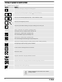
Tab. 1: Identifier and error displays:
Identifier Meaning
The pump is working or waiting for a starting signal.
The pump was manually stopped using the
[STOP/START]
key.
The pump was remotely stopped (Pause) - via the "External" socket.
The pump was stopped by an error.
Only with cyclical batch metering: the pump is waiting for the next cycle.
‘memory’
Only in
‘CONTACT’
and
‘BATCH’
operating modes:
The "Stroke memory" auxiliary function has been set.
The pump is in
‘ANALOGUE’
operating mode.
The
‘Curve
è
linear’
type of processing is set.
The pump is in
‘ANALOGUE’
operating mode.
The
‘Curve
è
Upper side band’
type of processing is set.
‘AUX’
The pump is currently pumping at auxiliary capacity and/or auxiliary frequency.
dia
off
The diaphragm rupture warning system is disabled.
A "Flow Control" metering monitor is connected.
The timer is active.
Only with
‘Password’
: the pump software is locked.
Only with
‘Password’
: the pump software has been temporarily unlocked.
The pump is in the
‘Menu’
(Set up).
Further explanations can be found in the "Trouble‐
shooting" chapter.
Overview of equipment and control elements
16

The pump only shows the metering volume and the
capacity in the calibrated state in l or l/h or in gal or
gal/h.
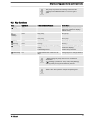
4.2 Key functions
Key Application In the continuous displays In the menu
[Back]
press - Move back to the previous menu
point (or a continuous display) -
without saving
[STOP/
START]
press Stop pump, Stop pump,
Start pump Start pump
[Menu]
press Move to the menu Move back to a continuous display
[Priming]
press Priming * Priming *
[Clickwheel]
press Start batch (only in
‘Batch’
operating
mode),
Acknowledge errors
Move to next menu option (or a
continuous display)
Confirm entry and save
[Clickwheel]
turn Switch between the continuous dis‐
plays
Change figure or change selection
* When priming the pump does not run at maximum
stroke rate.
If
[Priming] is pressed in ‘Stop’ state, then [Priming]
has top priority as long as the button is pressed.
Refer to the "Set-up basics" chapter to adjust figures
Overview of equipment and control elements
17

5 Functional description
5.1
Pump
The metering pump is an oscillating diaphragm pump, the stroke length of
which can be adjusted. An electric motor drives it. The slide rod transmits
the stoke motion to the diaphragms.
The stroke movement of the displacement body is continuously detected
and regulated so that the stroke is performed according to a previously set
metering profile - see chapter.
‘Metering’
‘setting’
.
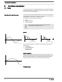
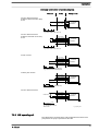
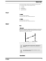
The following metering profiles are available:
n Normal
n Metering optimised
n Priming optimised
Every metering profile is ineffective below the switch-
over frequency for Start/Stop mode.
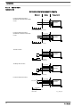
Normal
0
s s
a)
180 360 0
b)
180 360
ω ω
P_PL_0009_SW
Fig. 9: Stroke movement at a) maximum stroke length and b) reduced
stroke length.
s Stroke velocity
⍵ Cam rotational angle
+ Discharge stroke
- Suction stroke
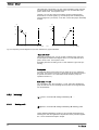
Metering optimised
With a metering optimised metering profile, the discharge stroke is elon‐
gated and the suction stroke is executed as quickly as possible. This set‐
ting is for example suitable for those applications that require optimum
mixing ratios and the most continuous chemical mixing possible.
Priming optimised
Illustration of the stroke movement
P_SI_0120_SW
s
t
P_SI_0103_SW
s
t
Functional description
18

With a priming optimised metering profile, the suction stroke is elongated
as much as possible, which facilitates the precise and problem-free
metering of viscous and gaseous media. Select this setting to minimise the
NPSH value as well.
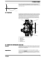
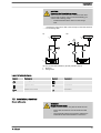
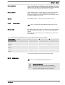
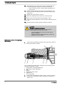
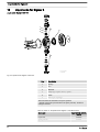
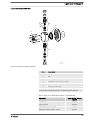
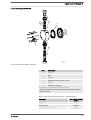
5.2
Liquid end
The diaphragm (2) hermetically shuts off the pump volume of the dosing
head (4) towards the outside. The suction valve (1) closes as soon as the
diaphragm (2) is moved in to the dosing head (4) and the feed chemical
flows through the discharge valve (3) out of the dosing head. The dis‐
charge valve (3) closes as soon as the diaphragm (2) is moved in the
opposite direction due to the vacuum pressure in the dosing head and
fresh feed chemical flows through the suction valve (1) into the dosing
head. One cycle is thus completed.
4
2
1
5
3
13
Fig. 10: Cross-section through the liquid end
1 Suction valve
2 Diaphragm
3 Discharge valve
4 Dosing head
5 Backplate
13 Safety diaphragm
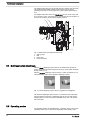
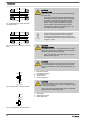
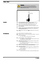
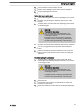
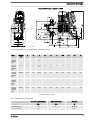
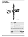
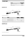
5.3 Bleed valve and integrated relief valve
Turning the rotary dial (3) on the bleed valve to "open" causes it to open
and the liquid end can be bled. Or it is used as a priming aid for priming
against pressure. The feed chemical flows out through the hose connec‐
tion (5), e.g. into a storage tank.
The integral relief valve operates in the "close" position as a simple,
directly controlled relief valve. As soon as the pressure exceeds the pres‐
sure value, which is preset using the large spring (1), it lifts the ball (2).
The feed chemical flows out through the hose connection (5), e.g. into a
storage tank.
P_SI_0104_SW
s
t
Bleed valve
Integral relief valve
Functional description
19

The integral relief valve can only protect the motor and the gear, and then
only against impermissible positive pressure that is caused by the
metering pump itself. It cannot protect the system against positive pres‐
sure.
The integral relief valve works as a bleed valve as soon as the rotary dial
(3) is turned to "open": The valve opens and the liquid end can be bled. Or
it is used as a priming aid for priming against pressure.
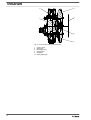
1 2
5
3
P_SI_0109
Fig. 11: Relief valve and integrated relief valve
1 Spring, large
2 Ball
3 Rotary dial
5 Hose connection
5.4 Multi-layer safety diaphragm
With the visual diaphragm rupture sensor, the lowered red cylinder (6)
springs forward beneath the transparent cover (7) so that it then becomes
clearly visible
Fig. 12.
With the electrical diaphragm rupture sensor, a switch is switched. A con‐
nected signalling device must signal the diaphragm rupture.
Fig. 12: Visual diaphragm rupture sensor, triggered and untriggered
The electrical diaphragm rupture sensor is connected to the "diaphragm
rupture indicator" terminal. If a diaphragm ruptures, the red LED "Fault"
display lights up on the pump and the identifier "Error" and
‘dia’
flash on
the LCD screen.
5.5 Operating modes
The operating modes are selected via the
‘Operating mode’
menu (some
operating modes may not be present depending on the identity code.)
Functional description
20
La pagina si sta caricando...
La pagina si sta caricando...
La pagina si sta caricando...
La pagina si sta caricando...
La pagina si sta caricando...
La pagina si sta caricando...
La pagina si sta caricando...
La pagina si sta caricando...
La pagina si sta caricando...
La pagina si sta caricando...
La pagina si sta caricando...
La pagina si sta caricando...
La pagina si sta caricando...
La pagina si sta caricando...
La pagina si sta caricando...
La pagina si sta caricando...
La pagina si sta caricando...
La pagina si sta caricando...
La pagina si sta caricando...
La pagina si sta caricando...
La pagina si sta caricando...
La pagina si sta caricando...
La pagina si sta caricando...
La pagina si sta caricando...
La pagina si sta caricando...
La pagina si sta caricando...
La pagina si sta caricando...
La pagina si sta caricando...
La pagina si sta caricando...
La pagina si sta caricando...
La pagina si sta caricando...
La pagina si sta caricando...
La pagina si sta caricando...
La pagina si sta caricando...
La pagina si sta caricando...
La pagina si sta caricando...
La pagina si sta caricando...
La pagina si sta caricando...
La pagina si sta caricando...
La pagina si sta caricando...
La pagina si sta caricando...
La pagina si sta caricando...
La pagina si sta caricando...
La pagina si sta caricando...
La pagina si sta caricando...
La pagina si sta caricando...
La pagina si sta caricando...
La pagina si sta caricando...
La pagina si sta caricando...
La pagina si sta caricando...
La pagina si sta caricando...
La pagina si sta caricando...
La pagina si sta caricando...
La pagina si sta caricando...
La pagina si sta caricando...
La pagina si sta caricando...
La pagina si sta caricando...
La pagina si sta caricando...
La pagina si sta caricando...
La pagina si sta caricando...
La pagina si sta caricando...
La pagina si sta caricando...
La pagina si sta caricando...
La pagina si sta caricando...
La pagina si sta caricando...
La pagina si sta caricando...
La pagina si sta caricando...
La pagina si sta caricando...
La pagina si sta caricando...
La pagina si sta caricando...
La pagina si sta caricando...
La pagina si sta caricando...
La pagina si sta caricando...
La pagina si sta caricando...
La pagina si sta caricando...
La pagina si sta caricando...
La pagina si sta caricando...
La pagina si sta caricando...
La pagina si sta caricando...
La pagina si sta caricando...
La pagina si sta caricando...
La pagina si sta caricando...
La pagina si sta caricando...
La pagina si sta caricando...
La pagina si sta caricando...
La pagina si sta caricando...
La pagina si sta caricando...
La pagina si sta caricando...
La pagina si sta caricando...
La pagina si sta caricando...
La pagina si sta caricando...
La pagina si sta caricando...
La pagina si sta caricando...
La pagina si sta caricando...
La pagina si sta caricando...
La pagina si sta caricando...
La pagina si sta caricando...
La pagina si sta caricando...
La pagina si sta caricando...
La pagina si sta caricando...
La pagina si sta caricando...
La pagina si sta caricando...
La pagina si sta caricando...
La pagina si sta caricando...
-
 1
1
-
 2
2
-
 3
3
-
 4
4
-
 5
5
-
 6
6
-
 7
7
-
 8
8
-
 9
9
-
 10
10
-
 11
11
-
 12
12
-
 13
13
-
 14
14
-
 15
15
-
 16
16
-
 17
17
-
 18
18
-
 19
19
-
 20
20
-
 21
21
-
 22
22
-
 23
23
-
 24
24
-
 25
25
-
 26
26
-
 27
27
-
 28
28
-
 29
29
-
 30
30
-
 31
31
-
 32
32
-
 33
33
-
 34
34
-
 35
35
-
 36
36
-
 37
37
-
 38
38
-
 39
39
-
 40
40
-
 41
41
-
 42
42
-
 43
43
-
 44
44
-
 45
45
-
 46
46
-
 47
47
-
 48
48
-
 49
49
-
 50
50
-
 51
51
-
 52
52
-
 53
53
-
 54
54
-
 55
55
-
 56
56
-
 57
57
-
 58
58
-
 59
59
-
 60
60
-
 61
61
-
 62
62
-
 63
63
-
 64
64
-
 65
65
-
 66
66
-
 67
67
-
 68
68
-
 69
69
-
 70
70
-
 71
71
-
 72
72
-
 73
73
-
 74
74
-
 75
75
-
 76
76
-
 77
77
-
 78
78
-
 79
79
-
 80
80
-
 81
81
-
 82
82
-
 83
83
-
 84
84
-
 85
85
-
 86
86
-
 87
87
-
 88
88
-
 89
89
-
 90
90
-
 91
91
-
 92
92
-
 93
93
-
 94
94
-
 95
95
-
 96
96
-
 97
97
-
 98
98
-
 99
99
-
 100
100
-
 101
101
-
 102
102
-
 103
103
-
 104
104
-
 105
105
-
 106
106
-
 107
107
-
 108
108
-
 109
109
-
 110
110
-
 111
111
-
 112
112
-
 113
113
-
 114
114
-
 115
115
-
 116
116
-
 117
117
-
 118
118
-
 119
119
-
 120
120
-
 121
121
-
 122
122
-
 123
123
-
 124
124


ProMinent S3Cb Operating Instructions Manual
- Categoria
- Attrezzatura per ossigeno
- Tipo
- Operating Instructions Manual
- Questo manuale è adatto anche per
in altre lingue
- English: ProMinent S3Cb
Documenti correlati
-
ProMinent gamma/ X GMXa Operating Instructions Manual
-
-
-
-
-
-
Altri documenti
-
Kyosho CA0501 Manuale utente
-
Grundfos DME 375 Installation And Operating Instructions Manual
-
Graymills Diaphragm One Quarter Inch Pump Polypropylene Manuale del proprietario
-
Grundfos DTS Installation And Operating Instructions Manual
-
CTX BOMBAPRO PH-RX Operating
-
Enerpac VE42AM Repair Service Instructions
-
-
Grundfos DMM 23 Installation And Operating Instructions Manual
-
-
Edgewater Networks 240IS Manuale del proprietario