B
Hardware Installation
© Copyright 2018 ATEN
®
International Co., Ltd.
ATEN and the ATEN logo are trademarks of ATEN International Co., Ltd. All rights reserved. All
other trademarks are the property of their respective owners.
Part No. PAPE-1223-P70G Printing Date: 11/2018
ATEN Control System – 8-button
Control Pad (US, 1 Gang)
Quick Start Guide
VK0100
ATEN VanCryst
™
A
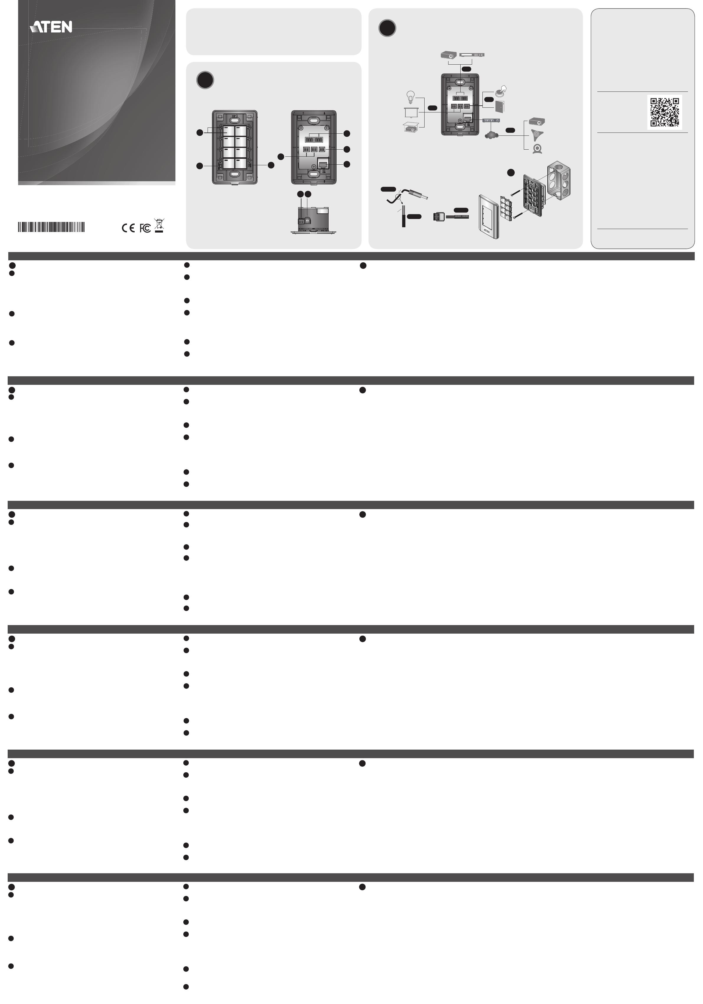
Hardware Overview
1
Buttons and LEDs
• Lights orange: The Control Pad is powered on and the button is off.
• Lights white: The Control Pad is powered on and the button is on.
• All LEDs blink orange and white once: The Control Pad is being set to
default. For details, see Reset Switch below.
• All LEDs repeatedly blink orange and white: A fi rmware upgrade is in
progress.
2
System LED Indicator
• LAN lights green: The Control Pad is connected to network.
• Link lights green: The Control Pad is actively transmitting and receiving
data.
• Both LEDs are off: The Control Pad is not connected to network.
3
Reset Switch
• To set the Control Pad’s network settings to default (IP address:
192.168.0.60 and subnet mask: 255.255.255.0), press the reset switch
once.
• To remove all data except the network settings, press and hold the reset
switch until all button LEDs blink once.
4
RS-232 Serial Ports
• Connect up to 2 RS-232 serial devices.
5
Relay Channels
• Connect up to 2 relay devices.
• Relay contacts are normally open, isolated with a contact rating of 24VDC,
1A max.
6
Digital Input Port
• Connects to 1 digital input device.
7
Ethernet Port
• Connects to an Ethernet cable to provide power and access to the network.
• LINK LED (left): Blinks green to indicate that the Control Pad is actively
transmitting and receiving data.
• ACT LED (right): Lights green to indicate a data transfer rate of 100 Mbps.
8
Control Pad ID Switch
• Use the switch to assign an ID to the Control Pad.
9
DC Power Port
• Connects to a 5V DC power adapter (optional).
B
Installation and Confi guration
Follow the steps below to safely install the Control Pad.
Step 1 Prepare the installation site
Prepare the installation site with proper dimensions to accommodate the
Control Pad. For dimensions information, visit the product web page to
download a CAD diagram.
Step 2 Connect the Control Pad to devices and LAN
2.1 Connect the Control Pad to serial, relay, and/or digital input devices using
the supplied terminal blocks.
Note: To provide additional ports to the Control Pad, purchase ATEN
Expansion Boxes.
2.2 To use PoE, connect the Control Pad to a PoE switch via an Ethernet cable.
2.3 If you do not have a power sourcing equipment for PoE, contact the sales
representative to purchase a power adapter and then follow the steps
below to prepare the power cord.
(a) Cut the connector end of the power adapter.
(b) Strip 5mm (0.5 cm) off the insulation cover of the Power Adapter cable
to expose two wires: a +5V wire and a GND (grounding) wire.
(c) Insert the exposed +5V wire and GND wire tightly into the provided
2-pin Terminal Block Connector.
VK0100 ATEN Control System – 8-button Control Pad (US, 1 Gang)
www.aten.com
Note: To determine an exposed wire’s polarity (i.e., +5V or GND), you can
use a voltmeter.
(d) Plug the power terminal block to the Control Pad.
2.4 Use the ID Switch to assign an ID to the Control Pad.
2.5 Power on all the devices. The button LEDs light orange.
Step 3 Install the Control Pad to the wall
Assemble the button caps and faceplate to the Control Pad, and then secure
the Control Pad to the wall using self-prepared screws.
Step 4 Confi gure the Control Pad using ATEN Confi gurator (VK6000)
4.1 Download and install ATEN Confi gurator from the web page.
4.2 Use ATEN Confi gurator to create a project profi le which specifi es button
layout, function, and the device connections.
4.3 Upload the project profi le to the Control Pad.
Note: If your network switch does not support DHCP, the Control Pad
adopts the default IP address (192.168.0.60).To change the IP
address, log in the web interface using the default IP address and
the default password (password).
Package Contents
1 VK0100 8-button Control Pad
1 Button Pack
6 Terminal Blocks
1 Faceplate
1 User Instructions
Support and Documentation Notice
All information, documentation, fi rmware,
software utilities, and specifi cations
contained in this package are subject to
change without prior notifi cation by
the manufacturer.
To reduce the environmental impact of our
products, ATEN documentation and software
can be found online at
http://www.aten.com/download/
Technical Support
www.aten.com/support
이 기기는 업무용(A급) 전자파적합기기로서 판매자 또는
사용자는 이 점을 주의하시기 바라며, 가정외의 지역에
서 사용하는 것을 목적으로 합니다.
Scan for
more information
EMC Information
FEDERAL COMMUNICATIONS COMMISSION INTERFERENCE
STATEMENT:
This equipment has been tested and found to comply with the limits
for a Class A digital device, pursuant to Part 15 of the FCC Rules.
These limits are designed to provide reasonable protection against
harmful interference when the equipment is operated in a commercial
environment. This equipment generates, uses, and can radiate radio
frequency energy and, if not installed and used in accordance with
the instruction manual, may cause harmful interference to radio
communications. Operation of this equipment in a residential area
is likely to cause harmful interference in which case the user will be
required to correct the interference at his own expense.
FCC Caution: Any changes or modifi cations not expressly approved by
the party responsible for compliance could void the user's authority to
operate this equipment.
Warning: Operation of this equipment in a residential environment
could cause radio interference.
This device complies with Part 15 of the FCC Rules. Operation is subject
to the following two conditions: (1) this device may not cause harmful
interference, and (2) this device must accept any interference received,
including interference that may cause undesired operation.
A
Hardware Review
2.2
2.1
2.1
2.1
Screen
Projector Video Switch
Projector
Projector
Lift
Ethernet
Cable
Camera
Network
Lighting
Control
Conference
System
Door
Sensor
Dry Contact
Device
PoE Switch
Relay
RS-232
DI
3
2
3
4
9 8
7
5
1
6
Front View Rear View
Side View
2.3
(a)
2.3
(b)
2.3
(c)
+5V
+5V
GND
GND
5mm
(+)
(-)
A
Présentation du matériel
1
Boutons et diodes
• S'allume en orange : Le bloc de commande est allumé et le bouton est éteint.
• S'allume en blanc : Le bloc de commande est allumé et le bouton est allumé.
• Toutes les diodes clignotent une fois en orange et blanc : Le bloc de
commande est en cours de confi guration à la valeur par défaut. Pour plus de
détails, voir Bouton de réinitialisation ci-dessous.
• Toutes les diodes clignotent à plusieurs reprises en orange et blanc : Une mise
à niveau du microprogramme est en cours.
2
Indicateur à diode du système
• Le réseau s'allume en vert : Le bloc de commande est connecté au réseau.
• Le lien s'allume en vert : Le bloc de commande transmet et reçoit activement
des données.
•
Les deux diodes sont éteintes : Le bloc de commande n'est pas connecté au réseau.
3
Bouton de réinitialisation
• Pour défi nir les paramètres réseau du bloc de commande sur les valeurs par
défaut (adresse IP : 192.168.0.60 et masque de sous-réseau : 255.255.255.0),
appuyez une fois sur le bouton de réinitialisation.
• Pour supprimer toutes les données sauf les paramètres réseau, maintenez le
bouton de réinitialisation appuyé jusqu'à ce que toutes les diodes des boutons
clignotent une fois.
4
Ports série RS-232
• Connectez jusqu'à 2 périphériques série RS-232.
5
Canaux de relais
• Connectez jusqu'à 2 périphériques relais.
• Les contacts de relais sont normalement ouverts, isolés avec une tension
nominale de contact de 24 V CC, 1 A max.
6
Port d'entrée numérique
• Se connecte à 1 périphérique d'entrée numérique.
7
Port Ethernet
• Se connecte à un câble Ethernet pour fournir l'alimentation et l'accès au réseau.
• Diode LIEN (gauche) : Clignote en vert pour indiquer que le bloc de commande
transmet et reçoit activement des données.
• Diode ACT (droite) : S'allume en vert pour indiquer un taux de transfert de
données de 100 Mbps.
8
Commutateur d'ID du bloc de commande
• Utilisez le commutateur pour attribuer un ID au bloc de commande.
9
Port d'alimentation CC
• Se connecte à un adaptateur d'alimentation 5 V CC (en option).
B
Installation et confi guration
Suivez les étapes ci-dessous pour installer le bloc de commande en toute sécurité.
Étape 1 Préparez le site d'installation
Préparez un site d'installation aux dimensions appropriées pour accueillir le bloc
de commande. Pour obtenir des informations sur les dimensions, visitez la page
Web du produit pour télécharger un diagramme en CAO.
Étape 2 Connectez le bloc de commande aux périphériques et au réseau
local
2.1 Connectez le bloc de commande à des périphériques d'entrée série, relais
et/ou numériques à l'aide des borniers fournis.
Remarque : Pour fournir des ports supplémentaires au bloc de commande,
achetez des boîtiers d'extension ATEN.
2.2 Pour utiliser la fonction d'alimentation sur Ethernet (PoE), connectez le bloc
de commande à un commutateur PoE via un câble Ethernet.
2.3 Si vous n'avez pas d'équipement d'alimentation pour PoE, contactez le
représentant commercial pour acheter un adaptateur d'alimentation, puis
suivez les étapes ci-dessous pour préparer le cordon d'alimentation.
(a) Coupez l’extrémité du connecteur de l’adaptateur secteur.
(b) Dénudez 5 mm (0,5 cm) de gaine isolante sur le câble de l'adaptateur
d'alimentation pour exposer deux fi ls : un fi l +5 V et un fi l de terre.
Système de contrôle de ATEN VK0100 – bloc de commande à 8 boutons (US, 1 Gang)
www.aten.com
(c) Insérez le fi l +5 V et le fi l de terre dénudés dans le connecteur bornier à
2 broches fourni.
Remarque : Pour déterminer la polarité d'un fi l exposé (c.-à-d., +5 V ou
terre), vous pouvez utiliser un voltmètre.
(d) Branchez le bornier d'alimentation sur le bloc de commande.
2.4 Utilisez le commutateur d'ID pour attribuer un ID au bloc de commande.
2.5 Allumez tous les périphériques. Les diodes des boutons s'allument en orange.
Étape 3 Installez le bloc de commande sur le mur
Assemblez les capuchons de boutons et la plaque frontale au bloc de commande,
puis fi xez le bloc de commande au mur à l'aide de vis préparées par vos soins.
Étape 4 Confi gurez le bloc de commande avec le Confi gurateur ATEN
(VK6000)
4.1 Téléchargez et installez le Confi gurateur ATEN depuis la page Web.
4.2 Utilisez le Confi gurateur ATEN pour créer un profi l de projet qui spécifi e la
disposition des boutons, la fonction et les connexions des périphériques.
4.3 Transférez le profi l de projet sur le bloc de commande.
Remarque : Si votre commutateur réseau ne prend pas en charge DHCP, le bloc
de commande adopte l'adresse IP par défaut (192.168.0.60). Pour
modifi er l'adresse IP, connectez-vous à l'interface Web à l'aide de
l'adresse IP par défaut et du mot de passe par défaut (password).
A
Hardware Übersicht
1
Tasten und LEDs
• Leuchtet orange: Das Bedienfeld ist eingeschaltet und die Taste ist ausgeschaltet.
• Leuchtet weiß: Das Bedienfeld ist eingeschaltet und die Taste ist eingeschaltet.
• Alle LEDs blinken einmal orange und weiß: Das Bedienfeld wird auf die
Standardeinstellung gesetzt. Weitere Informationen fi nden Sie unter Reset-
Schalter unten.
• Alle LEDs blinken wiederholt orange und weiß: Eine Firmware-Aktualisierung
wird ausgeführt.
2
System LED Anzeige
• LAN leuchtet grün: Das Bedienfeld ist mit dem Netzwerk verbunden.
• Link leuchtet grün: Das Bedienfeld sendet und empfängt aktiv Daten.
• Beide LEDs sind aus: Das Bedienfeld ist nicht mit dem Netzwerk verbunden.
3
Reset-Schalter
• So stellen Sie die Netzwerkeinstellungen des Bedienfelds auf die
Standardeinstellungen (IP-Adresse: 192.168.0.60 und Subnetzmaske:
255.255.255.0), drücken Sie den Reset-Schalter einmal.
• Um alle Daten außer den Netzwerkeinstellungen zu entfernen, halten Sie
den Reset-Schalter gedrückt, bis alle Tasten-LEDs einmal blinken.
4
RS-232 serielle Anschlüsse
• Schließen Sie bis zu 2 serielle RS-232 Geräte an.
5
Relais-Kanäle
• Schließen Sie bis zu 2 Relaisgeräte an.
• Die Relaiskontakte sind normalerweise offen, isoliert mit einer Schaltleistung
von 24 V Gleichspannung, max. 1 A.
6
Digitaler Eingangsanschluss
• Wird an 1 digitales Eingangsgerät angeschlossen.
7
Ethernet Anschluss
• Wird an ein Ethernet-Kabel angeschlossen, um Strom und Zugang zum
Netzwerk zu gewährleisten.
• LINK LED (links): Blinkt grün, um anzuzeigen, dass das Bedienfeld aktiv Daten
sendet und empfängt.
• ACT LED (rechts): Leuchtet grün, um eine Datenübertragungsrate von 100
Mbps anzuzeigen.
8
Bedienfeld ID Schalter
• Verwenden Sie den Schalter, um dem Bedienfeld eine ID zuzuweisen.
9
Gleichstromanschluss
• Wird an ein 5 V Gleichspannungsnetzteil angeschlossen (optional).
B
Installation und Konfi guration
Führen Sie die folgenden Schritte aus, um das Bedienfeld sicher zu installieren.
Schritt 1 Vorbereitung des Montageortes
Bereiten Sie den Montageort mit den richtigen Abmessungen für die
Aufnahme des Bedienfeldes vor. Informationen zu den Abmessungen fi nden
Sie auf der Produktseite, wo Sie ein CAD-Diagramm herunterladen können.
Schritt 2 Verbinden Sie das Bedienfeld mit den Geräten und dem LAN
2.1 Verbinden Sie das Bedienfeld mit seriellen, Relais- und/oder digitalen
Eingabegeräten unter Verwendung der mitgelieferten Anschlussblöcke.
Hinweis: Um zusätzliche Anschlüsse für das Bedienfeld bereitzustellen,
erwerben Sie ATEN Erweiterungsboxen.
2.2 Um PoE zu verwenden, verbinden Sie das Bedienfeld über ein Ethernet-
Kabel mit einem PoE-Switch.
2.3 Wenn Sie kein Stromquellengerät für PoE besitzen, wenden Sie sich an den
Vertriebsmitarbeiter, um ein Netzteil zu kaufen, und führen Sie dann die
folgenden Schritte aus, um das Netzkabel vorzubereiten.
(a) Schneiden Sie das Steckerende des Netzteils ab.
(b) Entfernen Sie 5 mm (0,5 cm) von der Isolierabdeckung des Netzteilkabels, um
zwei Drähte freizulegen: einen +5 V Draht und einen GND (Erdung) Draht.
(c) Stecken Sie den freiliegenden +5 V Draht und den GND-Draht fest in
den vorgesehenen 2-poligen Anschlussblockstecker.
VK0100 ATEN Steuerungssystem – 8-Tasten Bedienfeld (US, 1 Gang)
www.aten.com
Hinweis: Eine Methode zur Bestimmung der Polarität einer freiliegenden
Leitung (z.B. +5 V oder GND) ist die Verwendung eines Voltmeters.
(d) Stecken Sie den Stromanschlussblock in das Bedienfeld.
2.4 Verwenden Sie den ID-Schalter, um dem Bedienfeld eine ID zuzuweisen.
2.5 Schalten Sie alle Geräte ein. Die Tasten-LEDs leuchten orange.
Schritt 3 Installieren Sie das Bedienfeld an der Wand
Montieren Sie die Tastenkappen und die Frontplatte am Bedienfeld und befestigen
Sie das Bedienfeld dann mit selbst vorbereiteten Schrauben an der Wand.
Schritt 4 Konfi gurieren Sie das Bedienfeld mit dem ATEN Konfi gurator
(VK6000)
4.1 Laden Sie den ATEN Konfi gurator von der Webseite herunter und
installieren Sie ihn.
4.2 Erstellen Sie mit dem ATEN Konfi gurator ein Projektprofi l, das Tastenlayout,
Funktion und Geräteanschlüsse festlegt.
4.3 Laden Sie das Projektprofi l in das Bedienfeld hoch.
Hinweis: Wenn Ihr Netzwerkswitch DHCP nicht unterstützt, übernimmt
das Bedienfeld die Standard IP-Adresse (192.168.0.60). Um die
IP-Adresse zu ändern, melden Sie sich an der Webschnittstelle
mit der Standard IP-Adresse und dem Standardpasswort
(password) an.
A
Vista general del hardware
1
Botones y LED
• Se ilumina en naranja: el Panel de control está activado y el botón está desactivado.
• Se ilumina en blanco: el Panel de control está activado y el botón está activado.
• Todos los LED parpadean en naranja y blanco una vez: se están restableciendo
los valores predeterminados del Panel de control. Si desea obtener información
detallada, consulte Interruptor de reseteo a continuación.
• Todos los LED parpadean en naranja y blanco varias veces: se está actualizando
el fi rmware.
2
Indicador LED del sistema
• LAN se ilumina en verde: el Panel de control está conectado a la red.
• Enlace se ilumina en verde: el Panel de control está transmitiendo y recibiendo
datos.
• Ambos LED apagados: el Panel de control no está conectado a la red.
3
Interruptor de reseteo
• Para restablecer los valores predeterminados de red del Panel de control
(dirección IP: 192.168.0.60; máscara de subred: 255.255.255.0), pulse el
interruptor de reseteo una vez.
•
Para eliminar todos los datos, excepto los ajustes de red, mantenga pulsado el
interruptor de reseteo hasta que los LED de todos los botones parpadeen una vez.
4
Puertos serie RS-232
• Conecte hasta 2 dispositivos serie RS-232.
5
Canales de retransmisión
• Conecte hasta 2 dispositivos de retransmisión.
• Los contactos de retransmisión suelen estar abiertos, aislados con una
especifi cación de contacto de 24 V CC, 1 A máx.
6
Puerto de entrada digital
• Se conecta a 1 dispositivo de entrada digital.
7
Puerto Ethernet
• Se conecta a un cable Ethernet para proporcionar alimentación y acceso a la red.
• LED DE ENLACE (izquierda): parpadea en verde para indicar que el Panel de
control está transmitiendo y recibiendo datos.
• LED DE ACTIVIDAD (derecha): se ilumina en verde para indicar una velocidad
de transferencia de datos de 100 Mbps.
8
Conmutador de ID del Panel de control
• Use el conmutador para asignar un ID al Panel de control.
9
Puerto de alimentación de CC
• Se conecta a un adaptador de CC de 5 V (opcional).
B
Instalación y confi guración
Siga los pasos indicados a continuación para instalar el Panel de control de
forma segura.
Paso 1 Preparar el lugar de instalación
Prepare un lugar de instalación con las dimensiones adecuadas para el Panel
de control. Si desea obtener información sobre las dimensiones, visite la página
web del producto para descargar un diagrama de CAD.
Paso 2 Conectar el Panel de control a los dispositivos y la LAN
2.1 Conecte el Panel de control a los dispositivos de entrada serie, de
retransmisión o digitales con los bloques de terminales incluidos.
Nota: Si desea añadir puertos al Panel de control, adquiera Cajas de
expansión ATEN.
2.2 Si desea usar PoE, conecte el Panel de control a un conmutador de PoE con
un cable Ethernet.
2.3 Si no tiene un equipo de alimentación para PoE, póngase en contacto con el
comercial para adquirir un adaptador de corriente y, a continuación, siga los
pasos que se indican a continuación para preparar el cable de alimentación.
(a) Corte el extremo del conector del adaptador de corriente.
(b) Quite 5 mm (0,5 cm) de la cubierta aislante del cable del adaptador de
corriente para exponer dos cables: un cable de +5 V y un cable de GND
(tierra).
VK0100 Sistema de control ATEN - Panel de control de 8 botones (EE. UU., 1 unidad)
www.aten.com
(c) Inserte fi rmemente los cables de +5 V y GND expuestos en el conector
de bloque de terminales de 2 pines incluido.
Nota: Para determinar la polaridad de un cable expuesto (es decir, +5 V o
GND), puede usar un voltímetro.
(d) Conecte el bloque de terminales de alimentación al Panel de control.
2.4 Use el conmutador de ID para asignar un ID al Panel de control.
2.5 Encienta todos los dispositivos. Los LED de los botones se iluminan en naranja.
Paso 3 Instalar el Panel de control en la pared
Monte las tapas de los botones y la placa frontal en el Panel de control y, a
continuación, fi je el Panel de control a la pared con tornillos (no incluidos).
Paso 4 Confi gurar el Panel de control con el Confi gurador ATEN (VK6000)
4.1 Descargue el Confi gurador ATEN de la página web e instálelo.
4.2 Use el Confi gurador ATEN para crear un perfi l de proyecto que especifi que
la distribución de los botones, la función y las conexiones de dispositivos.
4.3 Cargue el perfi l de proyecto en el Panel de control.
Nota: Si su conmutador de red no es compatible con DHCP, el Panel de
control adopta la dirección IP predeterminada (192.168.0.60).
Para cambiar la dirección IP, inicie sesión en la interfaz web con
la dirección IP predeterminada y la contraseña predeterminada
(password).
A
Panoramica hardware
1
Pulsanti e LED
• Luci arancioni: Il Pad di controllo è acceso e il pulsante è spento.
• Luci bianche: Il Pad di controllo è acceso e il pulsante è acceso.
• Tutti i LED lampeggiano una volta di arancione e bianco: È in corso
l'impostazione ai predefi niti del Pad di controllo. Per informazioni vedere
Interruttore di ripristino di seguito.
• Tutti i LED lampeggiano ripetutamente di arancione e bianco: È in corso
l'aggiornamento del fi rmware.
2
Indicatore LED di sistema
• Luce LAN verde: Il Pad di controllo è collegato alla rete.
• Luce Link verde: Il Pad di controllo sta trasmettendo e ricevendo i dati.
• Entrambi i LED sono spenti: Il Pad di controllo non è collegato alla rete.
3
Interruttore di ripristino
• Per impostare le impostazioni di rete del Pad di controllo ai predefi niti
(indirizzo IP: 192.168.0.60 e subnet mask: 255.255.255.0), premere una
volta l'interruttore di ripristino.
• Per rimuovere tutti i dati eccetto le impostazioni di rete, tenere premuto
l'interruttore di ripristino fi no a quando i LED dei pulsanti lampeggiano una volta.
4
Porte seriali RS-232
• Connettono fi no a 2 dispositivi seriali RS-232.
5
Canali relè
• Connette fi no a 2 dispositivi relè.
• I contatti relè sono normalmente aperti, isolati con un valore di contatto di
24 V CC, massimo 1 A.
6
Porta ingresso digitale
• Connette a 1 dispositivo di ingresso digitale.
7
Porta Ethernet
• Connette a un cavo Ethernet per fornire alimentazione e accedere alla rete.
• LED LINK (sinistro): lampeggia di verde per indicare che il Pad di controllo sta
trasmettendo e ricevendo i dati.
• LED ACT (destro): i illumina di verde per indicare una velocità di trasferimento
dei dati di 100 Mbps.
8
Interruttore ID Pad di controllo
• Usare l'interruttore per assegnare un ID al Pad di controllo.
9
Porta alimentazione CC
• Connette a un adattatore di alimentazione da 5 V CC (opzionale).
B
Installazione e confi gurazione
Seguire le procedure per installare in modo sicuro il Pad di controllo.
Passaggio 1 Preparare il sito di installazione
Preparare il sito di installazione con le dimensioni adatte per alloggiare il Pad
di controllo. Per le informazioni sulla dimensione, visitare la pagina web del
prodotto per scaricare il diagramma CAD.
Passaggio 2 Collegare il Pad di controllo ai dispositivi e alla LAN
2.1 Collegare il Pad di controllo ai dispositivi di ingresso seriale, relè, e/o
digitale utilizzando i blocchi terminale in dotazione.
Nota: per offrire ulteriori porte al Pad di controllo, acquistare le scatole di
espansione ATEN.
2.2 Per usare PoE, collegare il Pad di controllo all'interruttore PoE mediante un
cavo Ethernet.
2.3 Se non si dispone di un'apparecchiatura di alimentazione per PoE, contattare
il rappresentante alle vendite per acquistare una adattatore di alimentazione
e seguire i passaggi di seguito per preparare il cavo di alimentazione.
(a) Tagliare l'estremità del connettore dell'adattatore di alimentazione.
(b) Rimuovere 5 mm (0,5 cm) di copertura di isolamento del cavo
dell'adattatore di alimentazione per esporre due fi li: un fi lo +5 V e un
fi lo GND (terra).
Sistema di controllo ATEN VK0100 - Pad di controllo a 8 pulsanti (US, 1 gruppo)
www.aten.com
(c) Inserire il fi lo +5 V e il fi lo GND esposti nel connettore blocco terminale
a 2 pin fornito.
Nota: per determinare la polarità del fi lo esposto (ad esempio +5 V o
GND) è possibile utilizzare un voltmetro.
(d) Collegare il blocco terminale di alimentazione al Pad di controllo.
2.4 Usare l'interruttore ID per assegnare un ID al Pad di controllo.
2.5 Accendere tutti i dispositivi. I LED pulsante si illuminano di arancione.
Passaggio 3 Installare il Pad di controllo alla parete
Montare i copri pulsanti e la piastra sul Pad di controllo, quindi fi ssare il Pad di
controllo alla parete utilizzando le viti già pronte.
Passaggio 4 Confi gurare il Pad di controllo utilizzando il Confi guratore
ATEN (VK6000)
4.1 Scaricare e installare il Confi guratore ATEN dalla pagina web.
4.2 Usare il Confi guratore ATEN per creare un profi lo progetto che specifi chi il
layout del pulsante, la funzione e le connessioni del dispositivo.
4.3 Caricare il fi le progetto sul Pad di controllo.
Nota: se lo switch di rete non supporta DHCP, il Pad di controllo adotta
l'indirizzo IP predefi nito (192.168.0.60). Per cambiare l'indirizzo IP,
accedere all'interfaccia web utilizzando l'indirizzo IP predefi nito e la
password predefi nita (password).
A
Обзор оборудования
1
Кнопки и индикаторы
• Горит оранжевым: На блок управления подано питание, кнопка отжата.
• Горит белым: На блок управления подано питание, кнопка нажата.
• Все индикаторы один раз мигают оранжевым и белым: Для всех
параметров блока управления установлены значения по умолчанию.
Подробности см. в разделе Переключатель сброса ниже.
• Все индикаторы периодически мигают оранжевым и белым:
выполняется процесс обновления микропрограммы.
2
Индикатор системы
• Индикатор LAN горит зеленым: Блок управления подключен к сети.
• Индикатор канал горит зеленым: Блок управления активно передает и
принимает данные.
• Оба индикатора не горят: Блок управления не подключен к сети.
3
Переключатель сброса
• Нажмите переключатель сброса один раз для сброса сетевых
параметров блока управления и установки для них значений по
умолчанию (IP-адрес: 192.168.0.60, маска подсети: 255.255.255.0).
•
Для удаления всех данных, кроме сетевых параметров, нажмите и
удерживайте кнопку сброса, пока индикаторы всех кнопок не мигнут один раз.
4
Последовательные порты RS-232
• Подключение до 2 устройств с последовательным интерфейсом RS-232.
5
Каналы реле
• Подключение до 2 релейных устройств.
• Контакты реле нормально разомкнуты, они изолированы и рассчитаны
на 24 В пост. тока, 1 А макс.
6
Разъем цифрового входа
• Подключение 1 устройства цифрового входа.
7
Порт Ethernet
• Подключение кабеля Ethernet для подачи питания и доступа к сети.
• Индикатор LINK (левый): мигает зеленым, указывая на то, что блок
управления активно передает и принимает данные.
• Индикатор ACT (правый): горит зеленым, указывая на передачу
данных со скоростью 100 Мбит/с.
8
Переключатель идентификатора (ID) блока управления
• Используйте этот переключатель для назначения идентификатора
блоку управления.
9
Разъем питания пост. тока
• Подключение адаптера питания 5 В пост. тока (опция).
B
Установка и конфигурирование
Для безопасной установки блока управления выполните следующие
действия.
Шаг 1. Подготовьте монтажную площадку
Подготовьте монтажную площадку в точном соответствии с размерами
блока управления. Размеры см. на чертеже CAD, который можно
загрузить с веб-страницы продукта.
Шаг 2. Подключите блок управления к устройствам и LAN
2.1 С помощью прилагаемых клеммных разъемов подключите блок
управления к устройствам с последовательным интерфейсом, реле
и/или устройствам цифрового входа.
Примечание: Для увеличения числа портов блока управления
купите блоки расширения ATEN.
2.2 Для использования технологии PoE подключите блок управления к
коммутатору PoE с помощью кабеля Ethernet.
2.3 Если у вас нет оборудования, которое можно использовать как
источник питания по технологии PoE, то у торгового представителя
купите адаптер питания, а затем выполните указанные ниже
действия, чтобы подготовить шнур питания.
(a) отрежьте соединитель на конце шнура адаптера питания.
(b) на кабеле адаптера питания снимите 5 мм (0,5 см) изоляции, чтобы
открыть два провода: провод +5 В и провод заземления (GND).
(c) плотно вставьте зачищенные провода +5 В и заземления в
прилагаемый 2-контактный разъем клеммной колодки.
Система управления ATEN VK0100 – 8-кнопочный блок управления (US, 1 Gang)
www.aten.com
Примечание: Полярность зачищенного провода (то есть +5 В или
заземление) можно определить с помощью вольтметра.
(d) Подсоедините клеммный разъем питания к блоку управления.
2.4 Используйте переключатель ID для назначения идентификатора ID
блоку управления.
2.5 Включите питание на всех устройствах. Индикаторы кнопок
загорятся оранжевым.
Шаг 3. Установите блок управления на стену
Наденьте накладки кнопок, установите лицевую панель на блок
управления и затем прикрепите блок управления к стене с помощью
самостоятельно подготовленных шурупов.
Шаг 4. Сконфигурируйте блок управления с помощью приложения
Конфигуратор ATEN (VK6000)
4.1 Загрузите и установите приложение Конфигуратор ATEN с веб-страницы.
4.2 С помощью приложения Конфигуратор ATEN создайте профиль
проекта и задайте в нем компоновку кнопок, их функции и
подключения устройств.
4.3 Выгрузите профиль проекта в блок управления.
Примечание: если ваш сетевой коммутатор не поддерживает DHCP,
то блок управления применит IP-адрес, используемый
по умолчанию (192.168.0.60). Для изменения IP-
адреса войдите в веб-интерфейс, введя используемые
по умолчанию IP-адрес и пароль (password).
