
I544 GB I 08 18 31100383
1
WARNING!
– Carefully read the manual before the installation or use.
– This equipment is to be installed by qualified personnel, complying to current standards, to avoid damages or safety
hazards.
– Remove eventual dangerous voltage from the product before any maintenance operation on it.
– The manufacturer cannot be held responsible for electrical safety in case of improper use of the equipment.
– Products illustrated herein are subject to alteration and changes without prior notice. Technical data and descriptions
in the documentation are accurate, to the best of our knowledge, but no liabilities for errors, omissions or
contingencies arising therefrom are accepted.
– A circuit breaker must be included in the electrical installation of the building. It must be installed close by the
equipment and within easy reach of the operator.
It must be marked as the disconnecting device of the equipment: IEC/EN 61010-1 § 6.11.
– Fit the instrument in an enclosure or cabinet with minimum IP51 degree protection.
– Clean the instrument with a soft dry cloth, do not use abrasives, liquid detergents or solvents.
INTRODUCTION
The DME D122 is a single-phase active and reactive energy meter for direct connection, for currents up to 63A, equipped
with a built-in M-BUS serial interface.
The energy accuracy is compliant with standard IEC/EN 62053-21 class 1.
Apart from energy metering, it can measure additional indications, for a total of 14 measurements that can be visualized
on the backlighted LCD display.
The DME D122 has a standard 2U (36mm wide) modular housing and is supplied with sealable terminal blocks.
DESCRIPTION
– Modular DIN-rail housing, 2U (36mm wide).
– Direct connection for currents up to 63A.
– Active energy measure complies IEC/EN 62053-21 class 1.
– LCD display with backlight.
– Counter with 6+1 digits.
– Button for measure selection and programming.
– Total active and reactive energy meters.
– Partial active and reactive energy meters, resettable.
– Hour counter, total and partial.
– Pulse LED for active energy consumption.
– Indication of instantaneous consumption (active power).
– M-BUS interface.
SELECTION OF READINGS
– Pressing briefly the button it is possible to select the readings on the display, following the sequence in the table
reported below.
– Each measure is indicated by the correspondent icon in the lower part of the display.
– After one minute has elapsed after the last keystroke, the display moves automatically back to the total active energy
screen.
ATTENZIONE!!
– Leggere attentamente il manuale prima dell’utilizzo e l’installazione.
– Questi apparecchi devono essere installati da personale qualificato, nel rispetto delle vigenti normative impiantistiche,
allo scopo di evitare danni a persone o cose.
– Prima di qualsiasi intervento sull’apparecchio, rimuovere eventuali tensioni pericolose dall’apparecchio
– Il costruttore non si assume responsabilità in merito alla sicurezza elettrica in caso di utilizzo improprio del dispositivo.
– I prodotti descritti in questo documento sono suscettibili in qualsiasi momento di evoluzioni o di modifiche. Le
descrizioni ed i dati a catalogo non possono pertanto avere alcun valore contrattuale.
– Un interruttore o disgiuntore va compreso nell’impianto elettrico dell’edificio. Esso deve trovarsi in stretta vicinanza
dell’apparecchio ed essere facilmente raggiungibile da parte dell’operatore. Deve essere marchiato come il dispositivo
di interruzione dell’apparecchio: IEC/EN 61010-1 § 6.11.
– Installare lo strumento in contenitore e/o quadro elettrico con grado di protezione minima IP51.
– Pulire lo strumento con panno morbido, non usare prodotti abrasivi, detergenti liquidi o solventi.
INTRODUZIONE
Il DME D122 è un contatore di energia monofase per inserzione diretta, per correnti fino a 63A, dotato di interfaccia seriale
M-BUS.
La misurazione dell’energia è conforme alla norma IEC/EN 62053-21 classe 1.
Oltre alla misurazione dell’energia, è in grado di fornire ulteriori indicazioni, per un totale di 14 misure, che possono essere
visualizzati sull’ampio display LCD retroilluminato.
Il DME D122 ha un contenitore modulare standard di larghezza 2U (36 mm) ed è fornito di serie di coprimorsetti
piombabili.
DESCRIZIONE
– Esecuzione modulare 2U (36mm) per guida DIN.
– Inserzione diretta per correnti max 63A.
– Misura energia attiva conforme a IEC/EN 62053-21 classe 1.
– Display LCD retroilluminato.
– Contatore con 6+1 cifre.
– Tasto per la selezione delle misure e programmazione.
– Contatori di energia attiva e reattiva totali.
– Contatori di energia parziali azzerabili.
– Contaore totale e parziale.
– LED frontale a impulsi per energia attiva consumata.
– Indicazione consumo istantaneo (potenza attiva).
– Interfaccia M-BUS.
SELEZIONE MISURE
– Premendo brevemente il pulsante è possibile selezionare le misure sul display dello strumento, secondo la
sequenza indicata nella tabella riportata sotto.
– A ciascuna selezione corrisponde un’icona nella parte bassa del display, con l’unità di misura selezionata.
– Dopo un minuto senza premere il pulsante frontale, la misura si riposiziona sul contatore totale di energia attiva.
Icon Measurement Format
kWh Total active energy 000000,0
kWh + Part Partial active energy 000000,0
kvarh Total reactive energy 000000,0
kvarh + Part Partial reactive energy 000000,0
V Voltage 000,0
A Current 00,00
kW Active power 00,00
kvar Reactive power 00,00
PF Power factor 0,00
Hz Frequency 00,0
h ∂ Hour counter (hhhhh.mm) 00000,00
h + Part ∂ Partial hour counter (hhhhh.mm) 00000,00
kW +d ∑ Average active power (15 min demand) 00,00
kW+d+▲∑ Max avg. active power (max demand) 00,00
Icona Misura Formato
kWh Energia attiva totale 000000,0
kWh + Part Energia attiva parziale 000000,0
kvarh Energia reattiva totale 000000,0
kvarh + Part Energia reattiva parziale 000000,0
V Tensione 000,0
A Corrente 00,00
kW Potenza attiva 00,00
kvar Potenza reattiva 00,00
PF Fattore di potenza 0,00
Hz Frequenza 00,0
h ∂ Contaore (hhhhh.mm) 00000,00
h + Part ∂ Contaore parziale (hhhhh.mm) 00000,00
kW +d ∑ Potenza attiva media (demand su 15 min) 00,00
kW+ d +▲∑ Max potenza attiva media (max demand) 00,00
∂ These measurements are shown only enabling parameter P-08
∑ These measurements are shown only enabling parameter P-09
∂ Queste misure sono visibili solo abilitando il parametro P-08
∑ Queste misure sono visibili solo abilitando il parametro P-09
DME D122
GB
CONTATORE DI ENERGIA MONOFASE A INSERZIONE DIRETTA CON INTERFACCIA M-BUS
Manuale di installazione
I
LOVATO ELECTRIC S.P.A.
24020 GORLE (BERGAMO) ITALIA
VIA DON E. MAZZA, 12
TEL. 035 4282111
TELEFAX (Nazionale): 035 4282200
TELEFAX (International): +39 035 4282400
E-mail info@
LovatoElectric.com
Web www.
LovatoElectric.com
SINGLE-PHASE DIRECT CONNECTION ENERGY METER WITH M-BUS INTERFACE
Installation manual
METROLOGICAL LED
– The red LED on the front emits 1000 pulses for every kWh of consumed Energy (that is, one pulse every Wh).
– The pulsing frequency of the LED gives an immediate indication of the energy flowing in every moment.
– The pulse duration, LED colour and intensity are compliant with the reference standards that define its utilization in
order to verify the accuracy of the energy meter.
ENERGY FLOW INDICATION
– When the device detects a flow of active energy to the load, it shows a rotating icon in the top-right part of the display.
– When there is no active energy consumption or when the load draws less than the starting current the rotating icon
disappears.
M-BUS
– DME D122 supports two addressing ways: primary address from 1 to 250 and secondary address from 00000000 to
99999999.
– Baud rates: 300, 600, 1200, 2400, 4800, 9600, 19200, 38400 bps.
– Refer to the electrical schemes at the end of the manual to connect DME D122 to the bus in the proper way.
– For reference tables and application notes go to www.lovatoelectric.com to get the M-BUS guide (instruction number:
I513).
PROGRAMMABLE LIMIT THRESHOLD
– Through parameters from P-02 to P-07 it is possible to define the behaviour of a programmable limit threshold, whose
status can be read from the communication protocol (see modbus addresses table).
– The activation of the programmable limit threshold is shown on the display through the icon.
– Note: During parameter setting (setup) the status of the programmable limit threshold is not updated.
INCORRECT WIRING INDICATION
– In case of incorrect wiring, when the device detects a reverse energy flow, the display shows the blinking code Err 3.
– This error is caused by either reverse connection of current wires (terminals L↑ and L↓) or reverse voltage wiring
(terminals N - L↑).
– In these conditions, the energy is not counted.
LED METROLOGICO FRONTALE
– Il LED rosso frontale emette 1000 impulsi per ogni kWh di energia consumata (ovvero 1 impulso per ogni Wh).
– La frequenza di lampeggio del LED dà una immediata indicazione dell’entità della potenza richiesta in un determinato
istante.
– La durata del lampeggio, il colore e l’intensità del LED sono conformi alle norme che prescrivono il suo utilizzo ai fini
di una verifica metrologica della accuratezza dell’energy meter.
INDICAZIONE FLUSSO DI ENERGIA
– Quando lo strumento sta rilevando un flusso di energia verso il carico, il display visualizza nell’angolo in alto a destra
una icona rotante.
– Quando il carico non richiede energia attiva oppure quando la corrente assorbita è inferiore alla corrente di avviamento,
l’icona rotante scompare.
M-BUS
– DME D122 supporta due modi di indirizzamento: indirizzo primario da 1 a 250 e indirizzo secondario da 00000000 a
99999999.
– Velocità impostabili: 300, 600, 1200, 2400, 4800, 9600, 19200, 38400 bps.
– Consultare gli schemi in fondo al manuale per un corretto collegamento del DME D122 al bus.
– Per le tabelle di riferimento e note implementative fare riferimento alla guida M-BUS presente sul sito
www.lovatoelectric.com (numero istruzione: I513).
SOGLIA LIMITE PROGRAMMABILE
– Tramite i parametri da P-02 a P-07 è possibile definire il comportamento di una soglia limite programmabile, il cui
stato può essere letto tramite il protocollo di comunicazione (vedere tabella indirizzi modbus).
– L’attivazione della soglia limite programmabile è visualizzata tramite l’icona sul display.
– Nota: Durante l’impostazione dei parametri (Setup) lo stato della soglia limite programmabile non viene aggiornato.
INDICAZIONE DI COLLEGAMENTO ERRATO
• In caso di collegamento errato, quando l’apparecchio rileva un flusso di energia di direzione contraria, viene attivata
l’indicazione lampeggiante Err 3.
• Questo errore può essere provocato dalla inversione del collegamento della corrente (morsetti L↑ e L↓) oppure dalla
inversione dei morsetti della tensione (N - L↑).
• In queste condizioni l’energia non viene conteggiata.

I544 GB I 08 18 31100383
2
NAVIGATION WITH FRONT KEY
– To move through menus, use the following rules:
– A short click of the front key, indicated by , changes the current selection, shown on the display, with a new one
(the next).
– Pressing the key for a long time (> 3s), indicated with symbol , is used to confirm the displayed selection.
– Symbol indicates when the user must wait for the display to move to a new selection.
– To quit a menu, select the --ESC-- option.
ADVANCED FUNCTIONS
– To access the advanced functions, use the following procedure:
1. Starting from any visualization screen, press . If the password protection is disabled (factory default, password =
0000), display jumps directly to point 4, otherwise it will show PASS to inform that the access code must be entered
first.
2. Release the button. The display now waits for the password and indicates 0000. The single digits are flashing
sequentially. Pressing while a digit is flashing, that digit is incremented. Waiting for some seconds, the selection
moves to the next digit. After having entered the right password code, press to confirm.
3. If the entered password is wrong, the display shows PASS Er and goes back to normal visualization. If instead the
code is correct, it proceeds to next point.
NAVIGAZIONE TRAMITE TASTO FRONTALE
– Per muoversi fra i menu si usano le seguenti regole:
– Una breve pressione del tasto frontale, che indicheremo con , viene utilizzata per cambiare la selezione
attualmente visualizzata con una diversa, successiva.
– Una pressione prolungata (> 3s), che indicheremo con , viene invece utilizzata per confermare la selezione
visualizzata.
– Il simbolo indica quando è necessario attendere perché il display proponga una nuova scelta.
– Per uscire da un menu, selezionare --ESC--.
FUNZIONI AVANZATE
– Per accedere alle funzioni avanzate utilizzare la seguente procedura:
1. Partendo da una qualsiasi visualizzazione, premere . Se la protezione da password è disattivata (default di
fabbrica, password = 0000) il display salta direttamente al punto 4, altrimenti indica PASS per evidenziare la necessità
di inserire la password.
2. Rilasciare il tasto. Il display ora attende l’inserimento della password e indica 0000. Le singole cifre lampeggiano a
rotazione. Premendo mentre una cifra sta lampeggiando, essa viene incrementata. Attendendo qualche secondo,
la cifra successiva inizia a lampeggiare. Dopo avere inserito la password premere il tasto per confermare.
3. Se la password inserita non è corretta il display mostra PASS Er e torna alla visualizzazione normale. Se invece è
corretta, si passa al punto successivo.
4. The display shows the first item of the following list. To move through the list, click
•
CLEAR P = clearing of partial energy meters
•
CLEAR H = clearing of partial hour counter (if enabled)
•
CLEAR D = clearing of max demand values (if enabled)
•
SETUP = parameters programming (setup)
•
INFO = revision and checksum of internal software
•
--ESC-- = returns to normal operation
5. To select a function, press while the desired function is displayed.
6. If the button is never pressed for 60 consecutive seconds, the display goes back automatically to normal operation.
LOST OR FORGOTTEN PASSWORD
If password is lost or forgotten, after three consecutive faulty attempts to enter the password, the display shows a 6-digit
unlock code. Please contact LOVATO Electric customer service reporting this unlock code. The right password will be
provided. The user is then free to change setting it as desired in the usual way (parameter P.01).
4. Il display indica la prima delle scelte nella seguente lista. Per passare da una scelta alla successiva premere
•
CLEAR P = azzeramento contatori di energia parziali
•
CLEAR H = azzeramento contaore parziale (se abilitato)
•
CLEAR D = azzeramento max demand (se abilitato)
•
SETUP = programmazione parametri
•
INFO = revisione software e checksum interno
•
--ESC-- = ritorno al funzionamento normale
5. Per selezionare una funzione premere mentre viene visualizzata la funzione desiderata.
6. Se non vengono premuti tasti per 60 secondi l’apparecchio ritorna automaticamente al funzionamento normale.
PASSWORD DIMENTICATA O PERSA
Se la password viene dimenticata o persa, dopo tre tentativi consecutivi di inserimento password non corretta, il display
visualizza un codice di sblocco di 6 cifre. Contattare il customer service LOVATO Electric comunicando il codice di sblocco.
Verrà restituita la password per l’accesso. L’utente è poi libero di re-impostarla a piacimento (tramite il parametro P.01).
PARAMETER SETTING (SETUP)
– While display is showing SETUP, press .
– The display shows the first parameter code P-01.
– Short-click to move to next parameters P-02, P-03…, etc use .
– When the display indicates the code of the parameter that needs to be modified, press .
•
If it is a numeric parameter (password, thresholds, delays), the display shows its present value.
The single digits are flashing sequentially. Pushing while a digit is flashing, that digit is incremented. Waiting
some seconds, the selection moves to the next digit.
•
If instead, the parameter provides selection among different functions (e.g. output functions, measure etc), pressing
,
it is possible to sequentially select the desired one.
•
Confirm with to go back to parameter code selection.
– After last parameter code, display shows --ESC--. Pressing button in this moment, parameters are saved and
system goes back to normal operation.
IMPOSTAZIONE PARAMETRI (SETUP)
– Con il display che indica SETUP, premere .
– Il display indica il codice del primo parametro P-01.
– Per selezionare i parametri successivi P-02, P-03 … usare .
– Quando il display indica il codice del parametro che si desidera modificare, premere .
•
Se si tratta di un parametro numerico (password, soglie, ritardi), il display indica il valore attuale dell’impostazione
del parametro. Le singole cifre lampeggiano a rotazione. Premendo mentre una cifra sta lampeggiando, essa
viene incrementata. Attendendo, comincia a lampeggiare la cifra successiva.
•
Se invece il parametro prevede la scelta fra diverse opzioni (funzione uscita, misura) premendo si può
selezionare a rotazione la funzione voluta.
•
Confermando con si può tornare alla selezione parametri.
– Dopo l’ultimo codice parametro il display visualizza --ESC--. Premendo il tasto in questo momento, i parametri
vengono salvati e si torna al funzionamento normale.

I544 GB I 08 18 31100383
3
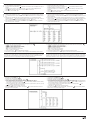
Code Description Default Range
P-01 Password 0000 0000 - 9999
P-02 Programmable limit threshold enable OFF OFF - THR
P-03 Threshold measure kW 01=kW - 02=kvar - 03=V
04=A - 05=Hz - 06=kWh Part 07=h
Part – 08 kW demand
P-04 ON threshold 100.00 0.00 – 999.99
P-05 ON delay 5 s 0 – 9999 sec.
P-06 OFF threshold 50.00 0.00 – 999.99
P-07 OFF delay 5 s 0 – 9999 sec.
P-08 Hour counter enable OFF OFF-ON-THR
P-09 Enable demand measures OFF OFF-ON
P-20 Primary address 001 001-250
P-21 Secondary address HIGH Serial n. 0000-9999
P-22 Secondary address LOW Serial n. 0000-9999
P-23 Serial speed 2400 300
600
1200
2400
4800
9600
19200
38400
SETUP PARAMETER TABLE
P-01 – If set to 0000 (default) the password protection is disabled.
P-02 – Defines the function of the programmable limit threshold:
OFF – Programmable threshold disabled.
THR – The programmable threshold is activated by a maximum or minimum limit, depending on values programmed in P-04 and P-06.
If P-04 > P-06, then the limit threshold activates when the measure defined by P-03 is higher than P-04, end de-activates when its value
becomes less than P-06 (maximum limit with hysteresis).
If P-04 < P-06, then the limit threshold activates when the measure defined by P-03 is lower than P-04, end activates when its value
becomes higher than P-06 (minimum limit with hysteresis).
P-03 – Selection of measure to compare with thresholds.
P-04 and P-05 – Threshold and delay for output activation. Note: The measurements are updated every 1 second, that means that the
variability of this delay is in the range from 0 to + 1 second.
P-06 and P-07 – Threshold and delay for output de-activation.
P-08 – Defines the hor counter operation:
OFF – hour counter disabled. It is not shown on the display.
ON – The hour counter is incremented as long as the energy meter is supplied.
THR – The hour counter is incremented as long as the threshold defined with previous parameter ( P-02, P-03, P-04 e P-05) is active.
P-09 – Enable of calculation and visualization of active energy demand and max demand.
P-20 – Primary address.
P-21 – Secondary address, first half (4 digits).
P-22 – Secondary address, second half (4 digits). The complete secondary address can be got by concatenating the content of
parameter P-21 with the one of parameter P-22. Example: secondary address 12345678, set P-21=1234 and P-22=5678.
P-23 – Baud rate.
Codice Descrizione Default Range
P-01 Password 0000 0000 - 9999
P-02 Abilitazione soglia limite programmabile OFF OFF - THR
P-03 Misura per soglia kW 01=kW - 02=kvar - 03=V
04=A - 05=Hz - 06=kWh Part 07=h
Part – 08 kW demand
P-04 Soglia ON 100,00 0,00 – 999,99
P-05 Ritardo soglia ON 5 sec. 0 – 9999 sec.
P-06 Soglia OFF 50,00 0,00 – 999,99
P-07 Ritardo soglia OFF 5 sec. 0 – 9999 sec.
P-08 Abilitazione contaore OFF OFF-ON-THR
P-09 Abilitazione misure demand OFF OFF-ON
P-20 Primary address 001 001-250
P-21 Secondary address HIGH Serial n. 0000-9999
P-22 Secondary address LOW Serial n. 0000-9999
P-23 Serial speed 2400 300
600
1200
2400
4800
9600
19200
38400
TABELLA PARAMETRI DI SETUP
P-01 – Se impostato a 0000 (default) la protezione da password è disabilitata.
P-02 – Definisce la funzione della soglia limite programmabile:
OFF
–
Soglia programmabile disabilitata.
THR
–
La soglia programmabile è attivata massima oppure di minima, a seconda dei valori impostati in P-04 e P-06.
Se P-04 > P-06, allora la soglia limite si attiva con la misura di P-03 > P-04, e si disattiva quando ritorna ad essere < P-06
(funzione di soglia massima con isteresi).
Se P-04 < P-06, allora la soglia limite si attiva con la misura di P-03 < P-04, e si disattiva quando ritorna ad essere > P-06
(funzione di soglia minima con isteresi).
P-03 – Selezione misura alla quale vengono applicate le soglie.
P-04 e P-05 – Soglia e relativo ritardo per attivazione uscita. Nota: le misure vengono aggiornate ed integrate 1 volta al
secondo, quindi questo ritardo ha una variabilità da 0 a + 1 secondo.
P-06 e P-07 – Come sopra, per disattivazione uscita.
P-08 – Definisce il funzionamento del contaore:
OFF – Contaore disabilitato, non viene visualizzato.
ON – Il contaore si incrementa fintanto che l’energy meter è alimentato.
THR – Il contaore si incrementa fintanto che la soglia definita con i parametri precedenti ( P-02, P-03, P-04 e P-05) è
attivata.
P-09 – Abilitazione misura e visualizzazione potenza attiva integrata attuale e massima (max demand).
P-20 – Indirizzo primario.
P-21 – Indirizzo secondario, prime 4 cifre.
P-22 – Indirizzo secondario, ultime 4 cifre. L’indirizzo secondario completo si ottiene concatenando il contenuto del
parametro P-21 con quello del parametro P-22.
Esempio: indirizzo secondario 12345678, occorre impostare P-21=1234 e P-22=5678.
P-23 – Velocità.
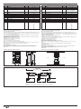
MECHANICAL DIMENSIONS AND WIRING DIAGRAMS
90
44.7
35.8
43.7
63
5
92.5
M-BUS CONNECTION
DME D122 n°1
Max 1000m
Max 25Ohm - 180pF
DME D122 n°250 *
M1 M2M2M1
M-Bus
M-Bus Master
M2M1
M-Bus
M1 M2M2M1
M-Bus
NOTE:
The number of connected devices depends on the Master unit load capacity
DIMENSIONI MECCANICHE E SCHEMI DI COLLEGAMENTO
CONNESSIONE M-BUS
L
L
M2
N
M1
DME D121
220...240V 50/60Hz
0.5-10 (63)A CI. 1
100...120V 50/60Hz
Energy meter
1000
Imp/kWh
LINE LOAD
N
N
L
L

I544 GB I 08 18 31100383
4
GB
TECHNICAL CHARACTERISTICS
Voltage
Nominal voltage Us 110 - 120V
~
/ 220 - 240V
~
Operating voltage range 88 – 132V
~
/ 187 – 264V
~
Nominal frequency 50 / 60Hz
Operating frequency range 45 - 66Hz
Power consumption/dissipation 1VA / 0.4W
Current
Minimum current (Imin) 0.5A
Transition current (Itr) 1A
Reference current (Iref - Ib) 10A
Max current (Imax) 63A
Start current (Ist) 40 mA
Accuracy
Active energy (IEC/EN62053-21) Class 1
LED pulse
Integration constant 1000 pulses / kWh
Pulse lenght 30ms
M-BUS (Slave)
Bus length According to M-Bus specification
Speed Programmable 300-38400 Baud
Typical current consumption ≤3mA (2 unit load)
Ambient operating conditions
Mounting Indoor use only
Operating temperature -25 - +55°C
Storage temperature -25 - +70°C
Relative humidity <80% non-condensing (IEC/EN 60068-2-78)
Maximum pollution degree 2
Overvoltage category III
Altitude ≤2000m
Climatic sequence Z/ABDM (IEC/EN 60068-2-61)
Shock resistance 10g (IEC/EN 60068-2-27)
Vibration resistance 0.7g (IEC/EN 60068-2-6)
Mechanical environment Class M1
Electromagnetic environment Class E1
Insulation voltage
Rated insulation voltage Ui 250V
~
Rated impulse withstand voltage Uimp 6kV
Power frequency withstand voltage 4kV
Supply / measure connections
Terminal type Screw (fixed)
Number of terminals 3 for Aux supply / measure
Cable cross section (min… max) 2.5 - 16 mm
2
Tightening torque 2 - 2.2 Nm
M-BUS interface connections
Type of terminals Screw (fixed)
Number of terminals 2
Conductor cross section (min… max) 0.5…4 mm
2
(20…11 AWG)
Tightening torque 1.3Nm (11.5lbin)
Housing
Version 2 modules (DIN 43880)
Mounting
35mm DIN rail (EN 60715) or by screw using extractible clips
Material Polyamide RAL 7035
Degree of protection IP40 on front ∂
Weight 148g
Certifications and compliance
Certifications EAC
Comply with standards IEC/EN 61010-1, IEC/EN 61000-6-2, IEC/EN 61000-6-3
∂
To comply with the protection requirements the meter must be mounted in a class IP51 enclosure or better. (IEC/EN 60529).
CARATTERISTICHE TECNICHE
Tensione
Tensione nominale Us 110 - 120V
~
/ 220 - 240V
~
Limiti di funzionamento 88 - 132V
~
/ 187 - 264V
~
Frequenza nominale 50 / 60Hz
Limiti di funzionamento 45 - 66Hz
Potenza assorbita/dissipata 1VA / 0,4W
Corrente
Corrente minima (Imin) 0,5A
Corrente di transizione (Itr) 1A
Corrente di riferimento (Iref - Ib) 10A
Corrente massima (Imax) 63A
Corrente di start (Ist) 40 mA
Accuratezza
Energia attiva (IEC/EN62053-21) Classe 1
Impulso LED
Costante di integrazione 1000 imp / kWh
Durata impulso 30ms
M-BUS (Slave)
Lunghezza bus Secondo specifiche M-Bus
Velocità Programmabile 300-38400 Baud
Assorbimento tipico ≤3mA (2 unit load)
Condizioni ambientali di funzionamento
Installazione Solo per uso interno
Temperatura d’impiego -25 - +55°C
Temperatura di stoccaggio -25 - +70°C
Umidità relativa <80% non condensante (IEC/EN 60068-2-78)
Grado di inquinamento ambiente massimo 2
Categoria dì sovratensione III
Altitudine ≤2000m
Sequenza climatica Z/ABDM (IEC/EN 60068-2-61)
Resistenza agli urti 10g (IEC/EN 60068-2-27)
Resistenza alle vibrazioni 0,7g (IEC/EN 60068-2-6)
Ambiente meccanico Classe M1
Ambiente elettromagnetico Classe E1
Tensione di isolamento
Tensione nominale d’isolamento Ui 250V
~
Tensione nominale di tenuta a impulso Uimp 6kV
Tensione di tenuta a frequenza d’esercizio 4kV
Connessioni circuito alimentazione / misura
Tipo di morsetti A vite (fissi)
N° morsetti 3 per alimentazione / misura
Sezione conduttori (min e max) 2,5 - 16 mm
2
Coppia di serraggio morsetti 2 - 2,2 Nm
Connessioni interfaccia M-BUS
Tipo di morsetti A vite (fissi)
N° morsetti 2
Sezione conduttori (min…max) 0,5…4 mm
2
(20…11 AWG)
Coppia di serraggio morsetti 1,3Nm (11,5lbin)
Contenitore
Esecuzione 2 moduli (DIN 43880)
Montaggio Guida 35mm (EN 60715) o a vite a mezzo clip estraibili
Materiale Poliammide RAL 7035
Grado di protezione IP40 sul fronte ∂
Peso 148g
Omologazioni e conformità
Omologazioni EAC
Conformi alle norme IEC/EN 61010-1, IEC/EN 61000-6-2, IEC/EN 61000-6-3
∂
Per garantire la protezione richiesta, lo strumento deve essere installato in contenitore con grado di protezione minimo
IP51 (IEC/EN60529).
I
-
 1
1
-
 2
2
-
 3
3
-
 4
4


in altre lingue
- English: Lovato DME D122 Installation guide
Altri documenti
-
LOVATO ELECTRIC DMED320 Manuale utente
-
Dell OptiPlex XE Guida utente
-
Vemer Energy-230 Multi Manuale utente
-
-
-
-
 CET LBP82 Manuale del proprietario
-
Athena C1 Manuale utente
-
CARLO GAVAZZI EM112DINAV11XS1X Guida d'installazione
-
