
CET - s.r.l.
Vers. 1.1
LBM 82
Pag. 1
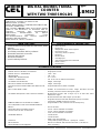
CET
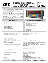
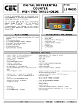
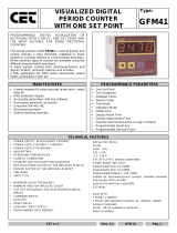
DIGITAL BIDIRECTIONAL
COUNTER
WITH TWO THRESHOLDS
Type:
LBM82
8 DIGITS VISUALIZED DIGITAL COUNTER WITH TWO
THRESHOLDS, SUITABLE TO OPERATE LIKE:
BIDIRECTIONAL COUNTER,
SINGLE DIRECTIONAL COUNTER WITH DIRECTION
UPCOUNT / DOWNCOUNT
THE COUNTER LBM 82 FINDS APPLICATION WHERE
THERE IS THE NECESSITY TO VISUALIZE AND TO
CONTROL, THROUGH TWO PROGRAMMABLE
THRESHOLDS, BIDIRECTIONAL OR SINGLE
DIRECTIONAL COUNTINGS FROM
ELECTROMECHANICAL AND LOGICAL CONTACTS,
PROXIMITY AND ENCODERS.
INSIDE THERE IS A BATCH COUNTER.
MAIN FEATURES
PROGRAMMABLE PARAMETERS
• Frontal keyboard in polycarbonate (antiscratch, antioil,
antiacid).
• IP65 protection degree
• Accessible parameters with key software
• Removable terminals connection.
• Execution DIN 48 x 96.
• Recessed assembly.
• Special retaining brackets.
• Two Threshold
• Reset Time
• Multiplication factor of the impulses
• Input (Slow / Fast)
• Count (Up / Down / Superior)
• Reset key
• Decimal Point
• Counting Input
• Auto Acknowledge of the Threshold
• Batch Counter
• Restart Input
TECHNICAL FEATURES
•
POWER SUPPLY IN ALTERNATE CURRENT
•
POWER SUPPLY IN DIRECT CURRENT
•
POWER SUPPLY TOLERANCE
•
ABSORPTION
•
OPERATING TEMPERATURE
•
CLIMATIC CONDITIONS
•
COUNTER VISUALIZATION
•
BATCH COUNTER VISUALIZATION
•
MULTIPLICATION COEFFICIENT THE INPULSES IN
INPUT
•
INPUT TYPE (NPN or PNP)
•
COUNTING FREQUENCY FOR LOGICAL SIGNALS
•
MINIMUM TIME FOR SLOW INPUT SIGNALS
•
CUT FREQUENCY FOR ELECTROMECHANICAL
INPUTS
•
AUXILIARY INPUTS POWER SUPPLY
(version /5 /12 /24 VDC on demand)
•
COMMAND IMPUTS
•
OUTPUTS
•
RELAY RESET
•
PROGRAMMED DATA MEMORY
: Single power 24 - 110 - 230 Vac (50 / 60 Hz).
: Single power 24 Vdc
: +10% - 15%.
: 2 W - 3 VA.
: -5 °C + 55 °C.
: U.R. 95 % at 40 °C (without condensate).
: 8 digits, 14mm high
: 5 digits, 14mm high
: Programmable from 0,00001 to 9,99999
.
: Suitable for Bi-directional Encoder, Single directional Encoder,
Proximity, electromechanical and logical signals
: Bi-directional Encoder with 4 edges up to 24 KHz with 4uSec
between the edges
: Bi-directional Encoder with 4 edges up to 40 KHz
: Single directional Encoder with directional input up to 40 KHz
: Upcounting / DOWNcounting up to 50 Hz
: Programmable in 25%, 50% and 75% of the frequency.
: from 10 to 50 Hz.
: 24 Vdc - 80 mA available on terminals.
: 12 Vdc - 80 mA available on terminals..
: 5 Vdc - 80 mA available on terminals.
: Counter Reset
: Counter Restart
: Inhibit / Auto Acknowledge
: 2 relays with operating contacts - capacity 2A - 250Vac.
: Manual or automatic with excitation time from 0,1 to 99,9 sec.
: static (no battery)

CET - s.r.l.
Vers. 1.1
LBM 82
Pag. 2
DESCRIPTION OF THE FRONTAL KEYBOARD
ø
YELLOW
The key 'LEFT ARROW' in normal operating phase visualizes, blinking, all the programmings executed
without the limitation of the insertion code. The time of scansion of the programmings is given from the
pressure of the same key. It exits automatically from this phase after 5 sec of the last pressure of the
same key.
In programming phase it moves the cursor of the figure towards left of a step, than at the beginning it is
on the right side first one on the. At the end it resumes from the first one to right.
ù
YELLOW
The key 'UP ARROW' in normal operating phase visualizes the Batch Counter.
In programming phase it increases the value of the blinking figure.
ú
BLUE
The key 'PRG' pressed for 2 sec. allows to enter in the programming phase, visualizing on display
C.0000.
In the programming phase, pressing key 'PRG' impulsively, it exits from the programming phase. The
instrument exits automatically from the programming phase, 60 sec. after the pressure of the last key.
û
RED
The key 'ENT/RES' in normal phase of counting has the 'RESET' function, with the modalities to it
attributed in the programming phase.
In programming phase it confirms and memorizes the visualized data and passes to the successive
function. If it has arrived to list end it resumes from the beginning.
INPUTS / OUTPUTS DESCRIPTION
DC POWER
(inputs 1 - 2) 24V DC Power Supply of the instrument.
AC POWER
(inputs 3 - 4) Power Supply of the instrument; it can be to 24 - 110 - 230 VAC according to demand.
12 VDC - 80mA
(inputs 6 - 7) 12 VDC - 80 mA auxiliary Power Supply that the instrument supply to feed Encoder and amplified
proximity.
RESTART
(input 8) RESTART input that executes the Restart of the counting from the programmed value in the RESTART
register.
RESET
(input 9) Input of RESET that executes the reset of the visualized count showed on display at the moment of its
activation.
INHIBIT/AUTOACK.
(input 10)
When active, it operates as inhibit of the counting or as Auto Acknowledge of the value on the display
as new Threshold value
CNT 1
(input 11) NPN counting input (PNP on demand) suitable for electromechanical contacts, amplified proximity, 3
wires sensors, bi-directional and single directional Encoders.
CNT 2
(input 12) NPN counting input (PNP on demand) suitable for electromechanical contacts, amplified proximity, 3
wires sensors, bi-directional and single directional Encoders.
RL1
(inputs 14-15-16)
Output of Relay 1, connected to the operation of the Threshold S1. The Common and Normally Opened
contacts are available.
RL2
(inputs 17-18-19)
Output of Relay 2, connected to the operation of the Threshold S2. The Common and Normally Opened
contacts are available.
DESCRIPTION OF THE LED’S OPERATION
LED 1 It comes activated to the reaching of the Threshold S1.
LED 2 It comes activated to the reaching of the Threshold S2.

CET - s.r.l.
Vers. 1.1
LBM 82
Pag. 3
PROGRAMMING OF THRESHOLD
For THRESHOLDS programming access, proceed as follow:
- Press key ‘PRG’ in impulsive mode; on display appears:
Ë1 <
99999999
S.1 = THRESHOLD 1, value programmable between - 9999999 and 99999999. Its operating mode
depend to the modality choose in the MODE parameter in GROUP 3.
Ë2 <
99999999
S.2 = THRESHOLD 2, value programmable between - 9999999 and 99999999. Its operating mode
depend to the modality choose in the MODE parameter in GROUP 3.
Key ENT confirms the data and passes to the successive programming. In order to exit the programming, press key PRG.
PROGRAMMING OF THE OPERATION PARAMETERS
The programmable parameters are divided in two groups and protect with a 4 figures code.
In order to approach the programming, proceed in the following way:
- Press key PRG for about 2 sec. On the display appears:
Cod
0000
GROUP 1
:
insert code
2357
and press
ENT
.
Ìê 0©0
t.r. = Automatic Time Reset, programmable from 00,0 up to 99,9 sec. This parameter allows to the
instrument to operate in automatic mode. When the counting reach the S1 value automatically it resets
the counting, excites the relay RL1 and restart the counting without lose impulses. The relay RL1 remains
ON for time programmed in t.r. programming. If the reset time programmed in t.r. is = 0 (00,0) the
instrument operates in manual mode.
Particular case: if the set up time t.r. is smaller of the time employed from the count to arrive to the values
of S.1 or S.2, the relative relays will never come unactived.
©00000
¾
F = 6 digits multiplier Factor, programmable from 0,1 to 9.99999.This parameter allows to convert the
number of the input impulses, showing them on the display in another format. If it programmed = 0 it
comes reprogrammed automatically to 1. If a value lower than 1 is inserted, it obtains the division of the
impulses. Es. I want to divide for 25 the impulses in input; calculation 1 : 25 = 0.04.
Attention: the variation of the value of the multiplying modifies automatically the value of the counting.
Cæ UP
Cæ dæ
Cæ SÈ
Cn. = Counting Mode: UP / DOWN / Superior.
UP = UP counting on rising edge
dn. = DOWN counting on rising edge
SP. = SUPERIOR, counting on rising edge getting over the Threshold.
Counting = Up: the counter gets ready to visualize the UP counting in rising edge mode, starting from
zero up to the programmed value of Threshold. To the counting’s end it actives the relative relay output.
Counting = dn: the counter gets ready to visualize the DOWN counting in rising edge mode, starting from
the programmed value of Threshold to zero. To the counting’s end it actives the relative relay output. This
programming operates with positive Thresholds only; negatives Thresholds are reprogrammed to 0.
Count = Sp: The operation is similar to UP Counting with the difference that to the reaching of the
threshold the instrument continues to count and can manually be resets to zero only. It operates with
positive and negative Thresholds. With Superior Counting, each time that the thresholds are overcoming
the Batch Counter is increased.
ê¿ 000
r.G. = CLEARANCE RECOVERY
It’s a 3 digit programmable value (0-999) that it’s summed to the Threshold value.
(Example: S1 = 10000, r.G. = 20, S1 actives at 10020, S3 = -2000, r.G. = 20, S3 actives at -2020)

CET - s.r.l.
Vers. 1.1
LBM 82
Pag. 4
Æê È
M.r. = Automatic Reset Mode. This parameter allows to program which Threshold, negative or positive,
must works in Automatic Reset. The instrument than will operate in the mode programmed in the GROUP
3 and with the thresholds values programmed.
P. = Two POSIVE Thresholds.
n. = Two NEGATIVE Thresholds.
P.n. = One POSITIVE Threshold and one NEGATIVE Threshold.
Two POSIVE Thresholds: The Automatic Reset works with the Threshold with the highest programmed
value between the two Thresholds.
Example: two independent Thresholds; S1 = 10000, S2 = -12000, the Automatic Reset starts when it
reaches the S1 value.
Two NEGATIVE Thresholds: The Automatic Reset works with the Threshold with the lowest programmed
value between the two negative Thresholds.
Example: two independent Thresholds; S1 = 10000, S2 = -12000, the Automatic Reset starts when it
reaches the S2 value.
One POSITIVE Threshold and one NEGATIVE Threshold: this mode integrates the two previous modes.
The Automatic Reset can be starts when reach the positive threshold and the negative threshold.
Example: two independent Thresholds; S1 = 10000, S2 = -1000, the Automatic Reset starts when it
reaches the S1 and S2 values.
Every time that the counting reaches a Threshold connected to the Automatic Reset the Batch Counter is
increased. The Threshold not connected to the Automatic Reset operates in Superior mode.
When DOWN counting is programmed, it’s not possible to have negative Thresholds.
Key ENT confirms the data and passes to the successive programming. In order to exit the programming, press key PRG.
PROGRAMMING OF THE OPERATION PARAMETERS
The programmable parameters are divided in two groups and protect with a 4 figure code.
In order to approach the programming, proceed in the following way:
- Press key PRG for about 2 sec. On the display appears:
Cod
0000
GROUP 2
:
insert code
2413
and press
ENT
.
APÈ æ
APP. = AUTO ACKNOWLEDGE.
This parameter allows to set on which threshold is active the Auto Acknowledge function. The function
allows to memorize the value visualized on the display as threshold value. If the Auto Acknowledge
function is active, when its input has closed, the value visualized on the display becomes the new
threshold value. The temporary lighting of the frontal leds signals the acknowledged. The Acknowledge
function remains active up to it has excluded by menu. When this function is not active, the input operates
as INHIBIT, that inhibits the counting for all time long that it’s close.
n. = Auto Acknowledge NOT ACTIVE. The INHIBIT function is active.
1 = Auto Acknowledge ACTIVE on THRESHOLD 1.
2 = Auto Acknowledge ACTIVE on THRESHOLD 2.
R êrË
1000
r.r.s. = REGISTRO DI RESTART. Value programmable between -9999999 and 99999999. Every time that
the RESTRT input is close, the programmed value is reload on the display. This programming is used to
Restart the counting from a programmed value. It can be activated in Impulsive or Continuously mode.
ȼ 0
ȼ 1
Programming of the Decimal Point of the Counter.
This programming allows to add a decimal point to the visualization on the 5 digits, in order to obtain
counts with various resolutions.
d.p. = 0 Decimal Point excluded; visualization 99999999
d.p. = 1 Decimal Point on the second display from right; visualization 9999999,9
d.p. = 2 Decimal Point on the third party display from right; visualization 999999,99
d.p. = 3 Decimal Point on the quarter display from right; visualization 99999,999
d.p. = 4 Decimal Point on fifth display from right; visualization 9999,9999
Attention, the Decimal Point is only fictitious, it doesn't realize any conversion.
reË 2
res = RESET KEY MODE. Programmable function of the frontal RES KEY
1 = INHIBITED RESET. It’s not possible to RESET with the RES key.
2 = ACTIVE RESET. It’s possible to RESET with the RES key.
3 = IMPULSIVE RESTART. The RES key operates as Impulsive RESTART.

CET - s.r.l.
Vers. 1.1
LBM 82
Pag. 5
bÁË æ
bl.S. = BLOCK OF THE PROGRAMMING OF THE THRESHOLD. This programming prevent the access
of the threshold programming.
n. = BLOCK NOT ACTIVE, it’s possible to access to the thresholds programming.
Y. = BLOCCO ACTIVE, it’s not possible to access to the thresholds programming.
êrË I
r.r.s. = RESTART INPUT MODE
This programming sets the operating mode of the RESTART function:
I. = IMPULSIVE RESTART
C. = CONTINUOUSLY RESTART WITH UNACTIVATION OF THE COUNTING.
IMPULSIVE: when active, the counter reload on display the value programmed in the Restart register
without stops to count. This command is instantaneously elaborated (interrupt mode).
CONTINUOUSLY: when active, the counter reload on display the value programmed in the Restart
register and remains stopped up to when the input becomes unactive.
1æê
In.r. = INPUT RESET MODE. This programming sets the operating mode of the Reset Input.
1 = The Reset Input resets the counting on display, the normal counting or the Batch Counter, depending
on what is showed on display.
2 = The Reset Input contemporaneously resets the counting and the Batch Counter.
¹Ë ê
A.S. = Threshold Activation.
With this programming is possible to active the new Threshold value directly quitting the programming or
quitting the programming after a Reset (with frontal RES key or with Reset input).
A.S. = P. Threshold activation quitting the programming.
A.S. = r. Threshold activation quitting the programming after a Reset.
Key ENT confirms the data and passes to the successive programming. In order to exit the programming, press key PRG.
PROGRAMMING OF THE OPERATION PARAMETERS
The programmable parameters are divided in two groups and protect with a 4 figure code.
In order to approach the programming, proceed in the following way:
- Press key PRG for about 2 sec. On the display appears:
Cod
0000
GROUP 3
:
insert code
2359
and press
ENT
.
MNodo
Modo = Selection of the operating mode of the CNT1 e CNT2 inputs.
bidi. 4 = BIDIRECTIONAL ENCODER, COUNTING ON 4 EDGES
bidi. 1 = BIDIRECTIONAL ENCODER, COUNTING ON 1 EDGE
Mono = SINGLE DIRECTIONAL, COUNTING on CNT1 input and DIRECTION on CNT2 input
Inc. dec = UP / DOWN COUNTER, INCREASING on CNT1input and DECREASING on CNT2 input
Fêì
Fr.t. = Cut Frequency for the Single Directional and UP / DOWN Counter modes.
This programming sets the Cut Frequency of the filter of the counting inputs.
This programming is available for the counting inputs programming Mono and Inc Dec only.
10 = SLOW up to 10 Hz
20 = SLOW up to 20 Hz
50 = SLOW up to 50 Hz
F. = FAST up to 40 kHz (not available for Inc. Dec programming)
¼Û 25
D.C. = DUTY CYCLE FOR THE SLOW CUT FREQUENCY.
This programming sets the duty cycle for the slow cut frequency programmed (not available for the Fast or
bidi programming).
25 = DUTY CYCLE 25 %
50 = DUTY CYCLE 50 %
75 = DUTY CYCLE 75 %
Setting 10 Hz (period = 100 mSec) and duty cycle 25 %,the impulse, to be read, must have a minimum ON
time of 25 mSec and a minimum OFF time of 75 mSec. The cut frequency and the duty cycle are
elaborated with a digital software filter; in this mode it’s possible to guarantee the maximum precision also
after many years of work.

CET - s.r.l.
Vers. 1.1
LBM 82
Pag. 6
ÆË 1
M.S. = OPERATING MODE OF THE THRESHOLDS
This programming sets the operating mode of the Thresholds.
1 = S1 MAIN THRESHOLD, S2 SECONDARY THRESHOLD IN OFFSET
2 = S1 MAIN THRESHOLD, S2 SECONDARY THRESHOLD IN ABSOLUTE
3 = TWO INDEPENDENT THRESHOLDS
In MODE 1, S2 = OFFSET, S2 is a threshold that comes activated always ahead the main threshold S1.
The programmed value is the value of the advance with which S2 will be active respect the threshold S1.
If S1 threshold is set 10000 and S2 is set 1000, the relay RL2 will be ON to 9000 and the Relay RL1 to
10000. If we change the S1 value, the RL2 will always be ON 1000 in advance respect S1.
The main threshold S1 can have a positive or negative value while S2 will always be a positive value,
being an Offset value. With positive values of S1, S2 can be programmed between 0 and S1 value.
(Example. S1 = 10000, S2 between 0 and 10000).
With negative values of S1, S2 can be programmed between 0 and the absolute positive value of S1
minus 1. (Example. S1 -20000, S2 between 0 and 19999).
If it’s programmed with a value out of this range it’s automatically reprogrammed to (S1-1).
In MODE 2, S2 = ABSOLUTE, S2 is an independent threshold that operates in SUPERIOR mode and
must be programmed between 0 and S1 value. If we change the S1 value, the S2 value doesn’t change.
With positive values of S1, S2 can be programmed between 0 and S1. (Example. S1 = 10000, S2 between
0 and 10000). With negative values of S1, S2 can be programmed between 0 and the value of S1 plus 1
(example S1 = -20000, S2 between 0 and -19999).
If it’s programmed with a value out of this range it’s automatically reprogrammed to (S1-1) or (S1 +1).
In MODE 3 all the thresholds are programmable in independence mode.
Key ENT confirms the data and passes to the successive programming. In order to exit the programming, press key PRG.
PROGRAMMING OF THE OPERATION PARAMETERS
The programmable parameters are divided in two groups and protect with a 4 figure code.
In order to approach the programming, proceed in the following way:
- Press key PRG for about 2 sec. On the display appears:
Cod
0000
GROUP 4
:
insert code
2415
and press
ENT
.
È 0000
P. = BATCH COUNTER
If programmed = 0, the Batch Counter is an absolute counter with 5 digits in increase that totalizes the
number of cycles. If it’s set to a value, it’s a Batch counter in decrease, starting for the value to 0. When it
reaches the 0 the counting is stopped with the Relays ON up to a Reset with the frontal RES key or by the
Reset input. In this case the Restart command is not active.
Key ENT confirms the data and passes to the successive programming. In order to exit the programming, press key PRG.

CET - s.r.l.
Vers. 1.1
LBM 82
Pag. 7
DECLARATION OF ‘CE’ CONFORMITY
Borgolavezzaro, October,03rd 2005
The building firm:
CET s.r.l.
Head office:
Strada Statale 211, Km 53,3
28071 Borgolavezzaro (No) ITALY
declare that the product:
type:
Digital Electronic Counter
model:
LBM82
use class:
Industrial
is in conformity with the following normatives:
EN55011
ENV50141
ENV50204
EN61000-4-2
EN61000-4-4
The manufacturing:
CET s.r.l.
________________________________
Signature
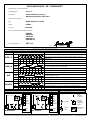
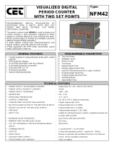
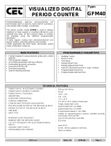
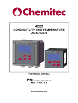
MODO DI FUNZIONAMENTO
MODE OPERATING DIAGRAM OPERATING DESCRIPTION
CNT1
CNT1, counting on an edge, for signals 90° out of p hase.
CNT2
CNT2 input, executes the inversion of the counting’s direction when it’s
ahead CNT1.
UP 0 1 2 3 4 5
4 3 2 1
Increasing visualization, from 0 to S programmed Threshold value.
BIDI x 1
DOWN S
S-1 S-2 S-3 S-4
S-5
S-4
S-3 S-2
S-1
Decreasing visualization, from S programmed Threshold value to 0.
CNT1
CNT1, counting on rising and falling edge, for signals 90° out of phase.
CNT2
CNT2, counting on rising and falling edge, executes the inversion of the
counting’s direction when it’s ahead CNT1.
UP 0 1 2 3 4 5 6 7 8
Increasing visualization, from 0 to S programmed Threshold value.
BIDI x 4
DOWN S
S-1 S-2 S-3 S-4 S-5 S-6 S-7 S-8
Decreasing visualization, from S programmed Threshold value to 0.
CNT1
CNT1, single directional counting input of the impulses.
CNT2
CNT2, executes the inversion of the counting’s direction from increasing to
decreasing and vice versa.
UP 0 1 2 1 0 -1 0 1 2
Increasing visualization, from 0 to S programmed Threshold value.
DIR
DOWN S
S-1 S-2 S-1 S S+1
S S-1 S-2
Decreasing visualization, from S programmed Threshold value to 0.
CNT1
CNT1, single directional counting input in increasing mode
CNT2
CNT2, single directional counting input in decreasing mode
UP 0 1 2 3 2 1 0 0 1
Increasing visualization, from 0 to S programmed Threshold value.
INC/DEC
DOWN S
S-1 S-2 S-3 S-2 S-1 S S S-1
Decreasing visualization, from S programmed Threshold value to 0.
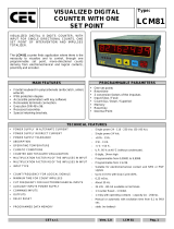
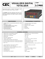
SENSORS CONNECTIONS
KEY
O
PEN
CLOSED
OPEN
6
8
9
10
11
12
7
LBM Terminals
GND
CNT2
CNT1
INHIBIT
RESET
RESTART
+24VDC
PNP SENSORS
7
8
9
10
11
12
6
LBM Terminals
+24VDC
CNT2
CNT1
INHIBIT
RESET
RESTART
GND
NPN SENSORS
Contatto
Voltage
Level
Open
collector
Transistor
Encoder,
Proximity
amplified or
3 wires
Bi-directional
Encoder

CET - s.r.l.
Vers. 1.1
LBM 82
Pag. 8
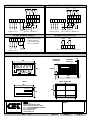
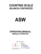
CONNECTIONS IN NEGATIVE LOGIC NPN
CONNECTIONS IN POSITIVE LOGIC PNP
24 VDC POWER SUPPLY
TRANSISTORS OUTPUTS
OVERALL DIMENSIONS (mm)
FRONTAL
SIDE
REAR
DRILL TEMPLATE
CET
CETCET
CET
CET
CETCET
CET
s.r.l.
Strada Statale 211 Km 53,550
28071 Borgolavezzaro - NO - ITALY
Tel : ++39 0321-885180/885301/885807
Fax : ++39 0321-885560
info@cet-italy.com
www.cet-italy.com
Agent:
158
130
9
19
44x92
REMOVABLE
TERMINALS
RETAINING
BRACKETS
10
MAX
93
45
48
96
ENT
RES
PROG
L1
L2
863259
Electronic counter
LBM
CET
-
8
9
10
11
12
13
19
18
17
16
15
14
CNT1
CNT2
NPN
RL2 RL1
RESTART INHIBIT/ACK
RESET
12Vdc
80mA
+
-
DC AC
POWER SUPPLY
-
+
7
1
2
3
4
5
6
8
9
10
11
12
13
19
18
17
16
15
14
CNT1
CNT2
PNP
RL2 RL1
RESTART INHIBIT/ACK
RESET
24Vdc
80mA
+
-
DC AC
POWER SUPPLY
-
+
7
1
2
3
4
5
6
12Vdc
80mA
+
-
DC AC
POWER SUPPLY
-
+
7
1
2
3
4
5
6
Max. Voltage 30VDC - Max. Current 100 mA
When the instrument
is fed to 24 VDC
connect the input 5
and 7 as showed.
92
44
1 2 3 4 5 6 7 8 9 10 11 12 13
19 18 17 16 15 14
OUT2
OUT1
19
18
17
16
15
14
-
 1
1
-
 2
2
-
 3
3
-
 4
4
-
 5
5
-
 6
6
-
 7
7
-
 8
8


CET LBP82 Manuale del proprietario
- Tipo
- Manuale del proprietario
- Questo manuale è adatto anche per
in altre lingue
- English: CET LBP82 Owner's manual
Documenti correlati
-
 CET LBM62 Manuale del proprietario
-
 CET LBM62/ID Manuale del proprietario
-
 CET LBM62/P Manuale del proprietario
-
 CET NFM42 Manuale del proprietario
-
 CET LCM81 Manuale del proprietario
-
 CET GFM41 Manuale del proprietario
-
 CET NCM52 Manuale del proprietario
-
 CET GFM40 Manuale del proprietario
-
 CET LCM60 Manuale del proprietario
-
 CET LFM40AN Manuale del proprietario


Altri documenti
-
Omega CN142 Series Manuale del proprietario
-
Omega CN243 Series Manuale del proprietario
-
-
 Chemitec 4222 Technical Manual
-
Lovato DME D122 Guida d'installazione
-
Carel heaterSteam Manuale utente
-
 BIS ASW Istruzioni per l'uso
-
Pepperl+Fuchs KC-LCD-24-24VDC Istruzioni per l'uso

