La pagina si sta caricando...

I386 GB I 10 13 31100190
1
LOVATO ELECTRIC S.P.A.
24020 GORLE (BERGAMO) ITALIA
VIA DON E. MAZZA, 12
TEL. 035 4282111
FAX (Nazionale): 035 4282200
FAX (International): +39 035 4282400
E-mail info@
LovatoElectric.com
Web www.
LovatoElectric.com
DMED320
WARNING!
– Carefully read the manual before the installation or use.
– This equipment is to be installed by qualified personnel, complying to current standards, to avoid
damages or safety hazards.
– Before any maintenance operation on the device, remove all the voltages from measuring and supply
inputs and short-circuit the CT input terminals.
– The manufacturer cannot be held responsible for electrical safety in case of improper use of the
equipment.
–
Products illustrated herein are subject to alteration and changes without prior notice.
–
Technical data and descriptions in the documentation are accurate, to the best of our knowledge, but no
liabilities for errors, omissions or contingencies arising therefrom are accepted.
–
A circuit breaker must be included in the electrical installation of the building. It must be installed close
by the equipment and within easy reach of the operator.
It must be marked as the disconnecting device of the equipment: IEC /EN 61010-1 § 6.11.2.
–
Fit the instrument in an enclosure or cabinet with minimum IP40 degree protection.
–
Clean the device with a soft dry cloth; do not use abrasive products, liquid detergents or solvents.
INDEX Page
Introduction ........................................................................................................................................... 1
Description ............................................................................................................................................. 1
Keyboard functions ................................................................................................................................ 1
Readings visualization ............................................................................................................................ 2
Display pages table ................................................................................................................................ 2
Main menu ............................................................................................................................................. 3
Password access ................................................................................................................................... 3
Setup parameters setting ....................................................................................................................... 4
Parameter table ...................................................................................................................................... 5
Energy meters page ............................................................................................................................... 6
Hour meters page .................................................................................................................................. 7
Trend graph page ................................................................................................................................... 7
Command menu .................................................................................................................................... 7
Wiring test ............................................................................................................................................. 8
Technical characteristics ........................................................................................................................ 9
Wiring diagrams .................................................................................................................................... 11
PC-DMED320 connection through RS485 interface .............................................................................. 12
Terminals position .................................................................................................................................. 12
Mechanical dimensions .......................................................................................................................... 12
INTRODUCTION
The energy counter DMED320 as been designed to join the maximum possible easiness of operation
together with a wide choice of advanced functions. Regardless of the compactness of the modular
housing (only 4U), the energy meter performances are the same of high-end devices. The graphic LCD
graphic display offers a user-friendly interface. The rich variety of functions, makes the DME series
energy counters the ideal choice for a wide range of applications.
DESCRIPTION
– Modular DIN-rail housing, 4U (72mm wide)
– Graphic LCD display, 128x80 pixels, white backlighting, 4 grey levels
– Membrane keyboard with 4 keys for visualization and setting
– Easy and fast navigation
– Compatible with LV, MV, HV applications
– Texts for measures, setup and messages in 5 languages
– Reading of 160 electrical parameters
– With built-in RS-485 interface
– True RMS measurements
– Continuous (gapless) sampling
– High accuracy.
KEYBOARD FUNCTIONS
and
keys - Used to scroll display pages, to select among possible choices, and to modify settings
(increment-decrement).
key - Used to rotate through sub-pages, to confirm a choice, to switch between visualization modes.
ATTENZIONE!!
– Leggere attentamente il manuale prima dell’utilizzo e l’installazione.
– Questi apparecchi devono essere installati da personale qualificato, nel rispetto delle vigenti normative
impiantistiche, allo scopo di evitare danni a persone o cose.
– Prima di qualsiasi intervento sull’apparecchio, togliere tensione dagli ingressi di misura e di
alimentazione e cortocircuitare i trasformatori di corrente.
– Il costruttore non si assume responsabilità in merito alla sicurezza elettrica in caso di utilizzo
improprio del dispositivo.
– I prodotti descritti in questo documento sono suscettibili in qualsiasi momento di evoluzioni o di
modifiche. Le descrizioni ed i dati a catalogo non possono pertanto avere alcun valore contrattuale.
– Un interruttore o disgiuntore va compreso nell’impianto elettrico dell’edificio. Esso deve trovarsi in
stretta vicinanza dell’apparecchio ed essere facilmente raggiungibile da parte dell’operatore. Deve
essere marchiato come il dispositivo di interruzione dell’apparecchio: IEC/ EN 61010-1 § 6.11.2.
– Installare lo strumento in contenitore e/o quadro elettrico con grado di protezione minimo IP40.
– Pulire l’apparecchio con panno morbido, non usare prodotti abrasivi, detergenti liquidi o solventi.
INDEX Page
Introduzione ........................................................................................................................................... 1
Descrizione ............................................................................................................................................ 1
Funzione dei tasti frontali ....................................................................................................................... 1
Visualizzazione delle misure ................................................................................................................... 2
Tabella delle pagine del display .............................................................................................................. 2
Menu principale ..................................................................................................................................... 3
Accesso tramite password ..................................................................................................................... 3
Impostazione dei parametri (setup) ....................................................................................................... 4
Tabella dei parametri .............................................................................................................................. 5
Pagina contatori di energia .................................................................................................................... 6
Pagina contaore ..................................................................................................................................... 7
Pagina grafico trend ............................................................................................................................... 7
Menu comandi ....................................................................................................................................... 7
Test di collegamento .............................................................................................................................. 8
Caratteristiche tecniche .......................................................................................................................... 10
Schemi di connessione .......................................................................................................................... 11
Connessione PC-DMED320 mediante interfaccia RS485 ....................................................................... 12
Disposizione morsetti ............................................................................................................................ 12
Dimensioni meccaniche ......................................................................................................................... 12
INTRODUZIONE
II contatore di energia DMED320 è stato progettato per unire la massima semplicità di utilizzo con una
ampia scelta di funzioni avanzate. Nonostante l’estrema compattezza del contenitore modulare (solo 4U),
le prestazioni del contatore di energia sono le stesse di un apparecchio di alto livello. Il display grafico
LCD consente una interfaccia utente intuitiva. La ricca dotazione di funzioni fanno dei contatori di energia
serie DME la soluzione ideale per un campo di applicazioni estremamente ampio.
DESCRIZIONE
– Esecuzione modulare 4U (72mm) per guida DIN.
– Display LCD grafico 128x80 pixel, retroilluminato bianco, 4 livelli di grigio.
– 4 tasti a membrana per visualizzazione ed impostazione.
– Navigazione rapida e semplice.
– Compatibile con reti BT, MT e AT.
– Testi per misure, impostazioni e messaggi in 5 lingue.
– 160 grandezze elettriche misurate.
– Interfaccia di comunicazione RS-485 integrata
– Misure in vero valore efficace (TRMS).
– Acquisizione continua (gapless).
– Elevata accuratezza.
FUNZIONE DEI TASTI FRONTALI
Tasti
e
- Servono per lo scorrimento fra le pagine video, per la selezione fra le possibili scelte
presentate a display e per la modifica di impostazioni (incremento/decremento).
Tasto - Serve per lo scorrimento delle sotto-pagine, per confermare una scelta effettuata e per
passare da una modalità all’ altra di visualizzazione.
THREE-PHASE ENERGY METER WITH CT CURRENT INPUTS
Instructions manual
GB
CONTATORE DI ENERGIA TRIFASE CON INGRESSI DI CORRENTE DA TA
Manuale operativo
I

I386 GB I 10 13 31100190
2
READING VISUALIZATION
– The
and
keys allow to scroll the readings visualization pages one by one. The content of the
present page is written in the title bar.
– Some of the readings may not be shown, depending on the programming and the wiring of the device
(for instance, if programmed-wired for a three-phase without neutral system, L-N voltage page is not
shown).
– For every page, the key allows to rotate through several sub-pages (for instance to show the
highest/lowest peak for the selected readings).
– The present dub-page is indicated in the status bar on the bottom of the display by one of the
following icons:
• IN = Instantaneous value – Present instantaneous value of the reading, shown by default every
time the page is changed.
• HI = Highest peak – Highest peak of the instantaneous value of the present reading. The HIGH
values are stored and kept even when auxiliary power is removed. They can be cleared using the
dedicated command (see command menu).
• LO = Lowest peak – Lowest value of the reading, stored from the time of the DME power-on. It is
resetted using the same command used for HI values.
• AV = Average value – Time-integrated value of the reading. Allows to show measurements with
slow variations. See integration menu in setup chapter.
• MD = Maximum Demand – Maximum peak of the integrated value. Stored in non-volatile memory
and it is resettable with dedicated command.
• GR = Bar graphs – Shows the measurements with bar graphs.
VISUALIZZAZIONE DELLE MISURE
– I tasti
e
consentono di scorrere le pagine di visualizzazione misure una per volta. La pagina
attuale è riconoscibile tramite la barra del titolo.
– Alcune delle misure potrebbero non essere visualizzate in funzione della programmazione e del
collegamento dell’apparecchio (ad esempio se programmato per un sistema senza neutro le misure
riferite al neutro non vengono visualizzate).
– Per ogni pagina, il tasto consente di accedere a delle sotto-pagine (ad esempio per visualizzare i
valori massimi e minimi registrati per la misura selezionata).
– La sottopagina visualizzata correntemente è indicata in basso a sinistra da una delle seguenti icone:
• IN = Valore istantaneo – Valore istantaneo attuale della misura, visualizzato di default ogni volta
che si cambia pagina.
• HI = Valore massimo istantaneo – Valore più alto misurato dal contatore di energia per la relativa
misura. I valori HIGH vengono memorizzati e mantenuti anche in assenza di alimentazione.
Possono essere azzerati tramite apposito comando (vedere menu comandi).
• LO = Valore minimo istantaneo – Valore più basso misurato dal contatore di energia dal momento
della messa in tensione. Viene resettato con lo stesso comando usato per i valori HI.
• AV = Valore integrato – Valore della misura integrato (mediato) nel tempo. Consente di vedere una
misura con variazioni lente. Vedere menu Integrazione.
• MD = Massimo valore integrato – Valore massimo del valore integrato (max demand). Rimane
memorizzato in memoria non volatile ed è resettabile con apposito comando.
• GR = Barre grafiche – Visualizzazione delle misure tramite barre grafiche.
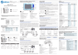
Indications on the main page
1 - Total imported active energy
2 - Power % bar graph
(present consumption)
3 - CT ratio setting
4 - Present active power
Indicazioni sulla pagina principale
1 - Energia totale importata
2 - Barra grafica potenza in %
(consumo attuale)
3 - Rapporto di trasformaz. TA
4 - Potenza attiva attuale
1 - Title bar
2 - Phase indication
3 - Sub-page indication
4 - Unit of measure
5 - Mesure
1 - Titolo pagina
2 - Indicazione fasi
3 - Indicazione sottopagina
4 - Unità di misura
5 - Misura
TABLE OF DISPLAY PAGES
Selection with
and
Selection with
N° PAGE SUB PAGES
1
ACTIVE ENERGY – ACTIVE POWER kWh(TOT) – kW (TOT) – Bar graph IMP EXP
2 ACTIVE ENERGY kWh(TOT) – kWh(PAR) IMP EXP
3 REACTIVE ENERGY kvarh(TOT) – kvarh(PAR) IMP EXP
4 APPARENT ENERGY kVA(TOT) – kVA(PAR)
5 ENERGY METERS - System kWh(IMP), kWh(EXP), kvarh(IMP), TOT PAR
kvarh(EXP), kVAh
6 L1 PHASE ENRGY METERS kWh(IMP), kWh(EXP), kvarh(IMP), TOT PAR
kvarh(EXP), kVAh
7 L2 PHASE ENRGY METERS kWh(IMP), kWh(EXP), kvarh(IMP), TOT PAR
kvarh(EXP), kVAh
8 L3 PHASE ENRGY METERS kWh(IMP), kWh(EXP), kvarh(IMP), TOT PAR
kvarh(EXP), kVAh
9 PHASE-TO-PHASE VOLTAGES V(L1-L2), V(L2-L3), V(L3-L1), HI LO AV GR
V(LL)EQV
10 PHASE-TO-NEUTRAL VOLTAGES V(L1-N), V(L2-N), V(L3-N), HI LO AV GR
V(L-N)EQV
11 PHASE AND NEUTRAL CURRENTS I(L1), I(L2), I(L3), I(N) HI LO AV MD GR
12 ACTIVE POWER P(L1), P(L2), P(L3), P(TOT) HI LO AV MD GR
13 REACTIVE POWER Q(L1), Q(L2), Q(L3), Q(TOT) HI LO AV MD GR
14 APPARENT POWER S(L1), S(L2), S(L3), S(TOT) HI LO AV MD GR
15 POWER FACTOR PF(L1),PF(L2),PF(L3),PF(EQ) HI LO AV GR
16 FREQUENCY-ASYMMETRY F, ASY(VLL), ASY(VLN), ASY(I) HI LO AV
17 DIST. ARMONICA TENSIONI L-L THD-V(L1-L2), THD-V(L2-L3), HI LO AV GR
THD-V(L3-L1)
18 DIST. ARMONICA TENSIONI L-N THD-V(L1),THD-V(L2),THD-V(L3) HI LO AV GR
19 DIST. ARMONICA CORRENTE THD-I(L1), THD-I(L2) THD-I(L3) HI LO AV GR
20 TREND GRAPH
21 HOUR COUNTER Hr(TOT), Hr(Partial)
22 INFO-REVISION-SERIAL NO. MODEL,REV SW, REV HW, SER. No.
23 LOGO
NOTE: Some of the pages listed above may not be available if the function they must view is not enabled.
For instance, if no alarms have been defined, then the Alarms page will not be shown.
TABELLA DELLE PAGINE DEL DISPLAY
Selezione con
e
Selezione con
N° PAGINE SOTTOPAGINE
1 ENERGIA ATTIVA – POTENZA ATTIVA kWh(TOT) – kW (TOT) – IMP EXP
Barra grafica
2 ENERGIA ATTIVA kWh(TOT) – kWh(PAR) IMP EXP
3 ENERGIA REATTIVA kvarh(TOT) – kvarh(PAR) IMP EXP
4 ENERGIA APPARENTE kVA(TOT) – kVA(PAR)
5 CONTATORI DI ENERGIA - Sistema kWh(IMP), kWh(EXP), TOT PAR
kvarh(IMP), kvarh(EXP), kVAh
6 CONTATORI DI ENERGIA FASE L1 kWh(IMP), kWh(EXP), TOT PAR
kvarh(IMP), kvarh(EXP), kVAh
7 CONTATORI DI ENERGIA FASE L2 kWh(IMP), kWh(EXP), TOT PAR
kvarh(IMP), kvarh(EXP), kVAh
8 CONTATORI DI ENERGIA FASE L3 kWh(IMP), kWh(EXP), TOT PAR
kvarh(IMP), kvarh(EXP), kVAh
9 TENSIONI CONCATENATE V(L1-L2), V(L2-L3), V(L3-L1), V(LL)EQV HI LO AV GR
10 TENSIONI DI FASE V(L1-N), V(L2-N), V(L3-N), V(L-N)EQV HI LO AV GR
11 CORRENTI DI FASE E DI NEUTRO I(L1), I(L2), I(L3), I(N) HI LO AV MD GR
12 POTENZA ATTIVA P(L1), P(L2), P(L3), P(TOT) HI LO AV MD GR
13 POTENZA REATTIVA Q(L1), Q(L2), Q(L3), Q(TOT) HI LO AV MD GR
14 POTENZA APPARENTE S(L1), S(L2), S(L3), S(TOT) HI LO AV MD GR
15 FATTORE DI POTENZA PF(L1),PF(L2),PF(L3),PF(EQ) HI LO AV GR
16 FREQUENZA – ASIMMETRIA F, ASY(VLL), ASY(VLN), ASY(I) HI LO AV
17 DIST. ARMONICA TENSIONI L-L THD-V(L1-L2), THD-V(L2-L3), HI LO AV GR
THD-V(L3-L1)
18 DIST. ARMONICA TENSIONI L-N THD-V(L1),THD-V(L2),THD-V(L3) HI LO AV GR
19 DIST. ARMONICA CORRENTE THD-I(L1), THD-I(L2) THD-I(L3) HI LO AV GR
20 GRAFICO TREND
21 CONTAORE Hr(TOT), Hr(Parziale)
22 INFO-REVISIONI-SERIAL NR. MODELLO,REV SW, REV HW,
Nr. SERIE
23 LOGO
NOTA: Alcune delle pagine elencate sopra potrebbero non essere visualizzate, se la funzione visualizzata
non è abilitata. Ad esempio se non viene programmato alcun allarme, la corrispondente pagina non viene
visualizzata.

I386 GB I 10 13 31100190
MENU PRINCIPALE
– Il menu principale è costituito da un insieme di icone grafiche che permettono l’accesso rapido alle
misure ed alle impostazioni.
– Partendo dalla visualizzazione misure normale, premere il tasto MENU. Il display visualizza il menu
rapido.
– Premere
per selezionare la funzione desiderata. L’icona selezionata viene evidenziata e la scritta
nella parte centrale del display indica la descrizione della funzione.
– Premere per attivare la funzione selezionata.
– Se alcune funzioni non sono disponibili la corrispondente icona sarà disabilitata, cioè visualizzata in
colore grigio.
– etc - Agiscono come scorciatoie che consentono di velocizzare
l’accesso alle pagine di visualizzazione misure, saltando direttamente al gruppo di misure selezionato,
partendo dal quale ci si potrà spostare avanti e indietro come di consueto.
– - Impostazione del codice numerico che consente l’accesso alle funzioni protette
(impostazione dei parametri, esecuzione di comandi).
– - Punto di accesso alla programmazione dei parametri. Vedere il capitolo dedicato.
– - Punto di accesso al menu comandi, dove l’utente abilitato può eseguire una serie di azioni di
azzeramento e ripristino.
MAIN MENU
– The main menu is made of a group of graphic icons (shortcuts) that allow rapid access to measures
and settings.
– Starting from normal visualisation, press MENU key. The main menu screen is displayed.
– Press
to select the desired function. The selected icon is highlighted and the central part of the
display shows the description of the function.
– Press to activate the selected function.
– If some functions are not available, the correspondent icon will be disabled, that is shown in light
grey colour.
– etc. - Shortcuts that allow to jump to the first page of that group.
Starting from that page it is still possible to move forward-backward in the usual way.
– - Open the password entry page, where it is possible to specify the numeric codes that unlock
protected functions (parameter setting, command menu etc.).
– - Access point to the setup menu for parameter programming.
– - Access point to the command menu, where the authorized user can execute some clearing-
restoring actions.
1 - Password entry
2 - Energy meters
3 - Voltage readings
4 - Current readings
5 - Power readings
6 - Frequency-Asymmetry
7 - Harmonic distortion
8 - Trend graph
9 - Hour counters
10 - Device Information
11 - Setup menu
12 - Commands menu
1 - Inserimento password
2 - Contatori di energia
3 - Visualizzazione Tensioni
4 - Visualizzazione Correnti
5 - Visualizzazione potenze
6 - Frequenza-asimmetria
7 - Distorsione armonica
8 - Grafico trend
9 - Visualizzazione contaore
10 - Informazioni apparecchio
11 - Impostazioni (Setup)
12 - Menu comandi
ACCESSO TRAMITE PASSWORD
– La password serve per abilitare o bloccare l’accesso al menu di impostazione ed al menu comandi.
– Per gli apparecchi nuovi di fabbrica (default), la password è disabilitata e l’accesso è libero. Se invece
le password sono state abilitate, per ottenere l’accesso bisogna prima inserire il relativo codice di
accesso numerico.
– Per abilitare l’uso delle password e definire i codici di accesso fare riferimento al capitolo
impostazione parametri.
– Esistono due livelli di accesso, a seconda del codice inserito:
• Accesso livello utente – consente l’azzeramento dei valori registrati ma non la modifica delle
impostazioni dell’apparecchio.
• Accesso livello avanzato – stessi diritti dell’utente con in più la possibilità di alterare le
impostazioni.
– Dalla normale visualizzazione misure, premere MENU per richiamare il menu principale, quindi
selezionare l’icona password e premere .
– Compare la finestra di impostazione password in figura:
PASSWORD ACCESS
– The password is used to enable or lock the access to setting menu (setup) and to command menu.
– For brand-new devices (factory default) the password management is disabled and the access is free.
If instead the passwords have been enabled and defined, then to get access it is necessary to enter
password first, specifying the numeric code through the keypad.
– To enable password management and to define numeric codes see setup menu.
– There are two access levels, depending on the code entered:
• User-Level access – Allows clearing of recorded values but not editing of setup parameters.
• Advanced access level – Same rights of the user access plus settings editing-restoring.
– From normal visualization, press MENU to recall main menu, select the password icon and press .
– The display shows the screen in picture:
– Con i tasti
si cambia il valore della cifra selezionata.
– Con il tasto si conferma la cifra e ci si sposta a rotazione sulle successive.
– Inserire la password, quindi spostarsi sull’icona della chiave.
– Quando la password inserita corrisponde alla password livello Utente o livello Avanzato, compare il
relativo messaggio di sblocco.
– Una volta sbloccata la password, l’accesso rimane abilitato fino a che:
• L’apparecchio viene disalimentato.
• L’apparecchio viene resettato (in seguito all’uscita dal menu impostazioni).
• Trascorrono più di 2 minuti senza che l’operatore tocchi alcun tasto.
– Con il tasto MENU si abbandona l’impostazione password e si esce.
– Keys
change the selected digit
– Key confirms the digit and moves to the next.
– Enter numeric code, then move on the key icon.
– If the password code entered matches the User access code or the Advanced access code, then the
correspondent unlock message is shown.
– Once unlocked the password, the access rights last until:
• The device is powered off.
• The device is resetted (after quitting the setup menu).
• The timeout period of two minutes elapses without any keystroke.
– To quit the password entry screen press MENU key.
3

I386 GB I 10 13 31100190
4
IMPOSTAZIONE DEI PARAMETRI (SETUP)
– Dalla normale visualizzazione misure, premere MENU per richiamare il menu principale,quindi
selezionare l’icona e premere per accedere al menu impostazioni.
– Viene visualizzata la tabella in figura, con la selezione dei sotto-menu di impostazione, nei quali sono
raggruppati tutti i parametri secondo un criterio legato alla loro funzione.
– Selezionare il sotto-menu desiderato tramite i tasti
e confermare con .
– Per uscire e tornare alla visualizzazione misure premere MENU.
PARAMETER SETTING (SETUP)
– From normal visualization, press MENU to recall main menu, then select icon and press
to open setup menu screen.
– The display will show the table in picture, with the parameters grouped in sub-menus with a function-
related criteria .
– Select the desired sub-menu with
keys and confirm with .
– To quit setup and go back to the readings visualization press MENU.
Cod. SUB-MENU DESCRIPTION
M01 GENERAL Rated data of the installation
M02 UTILITY Language, backlight, display pages etc.
M03 PASSWORD Access codes
M04 INTEGRATION Readings integration time
M05 HOUR METER Hour meter enable
M06 TREND GRAPH Trend graph reading and scale
M07 COMMUNICATION Communication port parameters (DMG210)
– The following table lists the available sub-menus:
Cod. SOTTO-MENU DESCRIZIONE
M01 GENERALE Dati caratteristici dell’impianto
M02 UTILITA’ Lingua, luminosità, pagine display ecc.
M03 PASSWORD Abilitazione protezione accesso
M04 INTEGRAZIONE Tempi di integrazione misure
M05 CONTAORE Abilitazione contaore
M06 GRAFICO TREND Definizione misura e scala grafico trend
M07 COMUNICAZIONE Parametri porta comunicazione
– Nella seguente tabella sono elencati i sottomenu disponibili:
– Select the sub-menu and press to show the parameters.
– Each parameter is shown with code, description and present setting value.
– Selezionare il sotto-menu e premere il tasto per visualizzare i parametri.
– Ciascun parametro è visualizzato con codice, descrizione e valore attuale.
– To modify the setting of one parameter, select it and then press .
– If the Advanced level access code has not been entered, i twill not be possible to enter editing page
and a access denied message will be shown.
– If instead the access rights are ok, then the editing screen will be shown:
– Se si vuole modificare il valore di un parametro, dopo averlo selezionato premere .
– Se non è stata immessa la password livello Avanzato, non sarà possibile accedere alla pagina di
modifica, e verrà visualizzato un messaggio di accesso negato.
– Se invece si ha l’accesso, verrà visualizzata la pagina di modifica
– When the editing screen is displayed, the parameter setting can be modified with
keys. The
screen shows the new setting, the maximum and minimum values, the factory default setting and a
graphic bar that shows the setting range.
– Pressing simultaneously
and
, the setting is set to factory default.
– Press MENU to go back to the parameter selection. The entered value is stored.
– Press MENU again to save all the settings and to quit the setup menu. The energy meter executes a
reset and goes back to normal operation.
– Quando si è in modalità modifica, il valore può essere modificato con
e
. Viene visualizzato il
valore precedente, i valori minimi e massimi possibili ed una barra grafica che indica il range di
impostazione.
– Premendo contemporaneamente
e
l’impostazione viene riportata al valore di default di fabbrica.
– Premere MENU per tornare alla selezione parametri. Il valore immesso rimane memorizzato.
– Premere di nuovo MENU per salvare i cambiamenti ed uscire dalla impostazione. Il contatore di
energia esegue un reset e ritorna in funzionamento normale.
1 - Parameter code
2 - Present setting value
3 - Selected parameter
4 - Parameter description
1 - Codice parametro
2 - Valore attuale
3 - Parametro selezionato
4 - Descrizione parametro
1 - Selected parameter
2 - New value entered
3 - Maximum possible setting
4 - Factory default setting
5 - Graph bar of the value-range
6 - Minimum possible setting
1 - Parametro selezionato
2 - Nuovo valore impostato
3 - Massimo valore possibile
4 - Valore di default di fabbrica
5 - Barra grafica valore-range
6 - Minimo valore possibile

I386 GB I 10 13 31100190
5
M01 – GENERAL UoM Default Range
P01.01 CT primary A 5 5-10000
P01.02 CT secondary A 5 5
P01.03 Rated voltage V Aut Aut / 50-500000
P01.04 Nominal power kW AUT AUT /
1 - 10000
P01.05 Use VT OFF OFF-ON
P01.06 VT primary V 100 50-500000
P01.07 VT secondary V 100 50-500
P01.08 Wiring
L1-L2-L3-N
L1-L2-L3-N
L1-L2-L3
L1-L2-L3-N BAL
L1-L2-L3 BAL
L1-N-L2
L1-N
PARAMETER TABLE
P01.01 – CT primary winding rated current.
P01.02 – CT secondary winding rated current. For DMED320 fixed to 5A.
P01.03 – Line rated voltage. Leaving to AUT the energy counter automatically adapts bar-graph full scale.
P01.04 – Plant nominal power. Leaving to AUT the energy meter automatically adapts bar-graph full
scale.
P01.05 – Set to ON if VT are used. If set to OFF, the following two parameters will be ignored.
P01.06 – VT primary winding rated voltage.
P01.07 – VT secondary winding rated voltage.
P01.08 – Set this parameter according to the used wiring diagram. See witring diagrams on last pages of
the manual.
M01 – GENERALE UdM Default Range
P01.01 Primario TA A 5 5-10000
P01.02 Secondario TA A 5 5
P01.03 Tensione nominale V Aut Aut / 50-500000
P01.04 Potenza nominale kW AUT AUT /
1 - 10000
P01.05 Utilizzo TV OFF OFF-ON
P01.06 Primario TV V 100 50-500000
P01.07 Secondario TV V 100 50-500
P01.08 Tipo di collegamento
L1-L2-L3-N
L1-L2-L3-N
L1-L2-L3
L1-L2-L3-N BIL
L1-L2-L3 BIL
L1-N-L2
L1-N
TABELLA PARAMETRI
P01.01 – Corrente nominale del primario dei TA.
P01.02 – Corrente del secondario dei TA. Per DMED320 fissa a 5 A.
P01.03 – Tensione nominale dell’impianto. Lasciando su AUT il contatore di energia adegua
automaticamente la scala delle barre grafiche.
P01.04 – Potenza nominale impianto. Lasciando su AUT il contatore di energia adegua automaticamente
la scala delle barre grafiche.
P01.05 – Programmare ad ON se vengono utilizzati dei TV. Se programmato ad OFF i successivi due
parametri vengono ignorati.
P01.06 – Tensione nominale primario TV.
P01.07 – Tensione nominale secondario TV.
P01.08 – Impostare concordemente allo schema di collegamento utilizzato. Vedere Schemi di
collegamento alla fine del manuale.
M02 – UTILITY UoM Default Range
P02.01 Language English English
Italiano
Francais
Espanol
Portoguese
P02.02 Display contrast % 50 0-100
P02.03 High backlight level % 100 10-100
P02.04 Low backlight level % 30 10-50
P02.05 Low backlight delay s 30 5-600
P02.06 Default page return s 60 OFF / 10-600
P02.07 Default page ENE+kW ENE+kW / kWh …
P02.08 Default sub-page INST INST / HI / LO /
AVG / MD /GRAPH
P02.09 Display update time s 0.5 0.1 – 5.0
P02.06 – If set to OFF the display remains always in the page where the user left it. If set to a time delay,
after that time the display page goes back to page set in P02.07.
P02.07 – Number of the page to which the display returns automatically after time specified by P02.06
has elapsed from the last keystroke.
P02.08 – Sub-page type to which the display returns after P02.06 has elapsed.
M02 – UTILITA’ UdM Default Range
P02.01 Lingua English English
Italiano
Francais
Espanol
Portoguese
P02.02 Contrasto LCD % 50 0-100
P02.03 Intensità retroilluminazione display alta % 100 10-100
P02.04 Intensità retroilluminazione display bassa % 30 10-50
P02.05 Tempo passaggio a retroilluminazione bassa s 30 5-600
P02.06 Ritorno a pagina di default s 60 OFF / 10-600
P02.07 Pagina di default ENE+kW ENE+kW / kWh …
P02.08 Sub-pagina di default INST INST / HI / LO /
AVG / MD /GRAPH
P02.09 Tempo di aggiornamento display s 0.5 0.1 – 5.0
P02.06 – Se impostato ad OFF il display rimane sempre nella pagina dove è stato lasciato dall’utente.
Se impostato ad un valore, dopo questo tempo il display ritorna alla pagina impostata con P02.07.
P02.07 – Numero della pagina alla quale il display ritorna automaticamente una volta che è trascorso il
tempo P02.06 dall’ultima pressione di un tasto.
P02.08 – Tipo di sotto-pagina alla quale il display torna dopo trascorso P02.06.
P03.01 – If set to OFF, password management is disabled and the access to setup parameters and
command menu is allowed.
P03.02 – When P.03.01 enabled, value to be specified to get user access.
P03.03 – Like P03.02, but referred to advanced access.
M03 – PASSWORD UoM Default Range
P03.01 Enable passwords OFF OFF-ON
P03.02 User level password 1000 0-9999
P03.03 Advanced level password 2000 0-9999
P03.01 – Se impostato ad OFF, la gestione delle password è disabilitata e l’accesso alle impostazioni e al
menu comandi è libero.
P03.02 – Con P03.01 attivo, valore da specificare per attivare l’accesso a livello utente. Vedere capitolo
Accesso tramite password.
P03.03 – Come P03.02, riferito all’accesso livello Avanzato.
M03 – PASSWORD UdM Default Range
P03.01 Utilizzo password OFF OFF-ON
P03.02 Password livello Utente 1000 0-9999
P03.03 Password livello Avanzato 2000 0-9999
P04.01 – Selection of average reading calculation method:
Fixed = Readings are integrated for the set time. Every time the integration time elapses, the Average
value is updated with the result of the last integration.
Shift = The instantaneous values are integrated for a period f time equal to 1/15th of the set time. Every
time this interval elapses, the oldest value is replaced with the new one just calculated. The average value
is updated every 1/15th of the time set, considering a time-sliding window that groups the last 15
calculated values, with a total length equal to integration time setting.
P04.02 = Average readings integration time, used for active, reactive and apparent power.
P04.03 = readings integration time, used for currents.
M04 – INTEGRATION UoM Default Range
P04.01 Integration mode Shift Fixed
Shift
P04.02 Power int. Time min 15 1-60min
P04.03 Current int. Time min 15 1-60min
P04.01 – Selezione della modalità di calcolo delle misure integrate.
Fisso = Le misure istantanee vengono integrate per il tempo impostato. Ad ogni scadenza del tempo, la
misura integrata viene aggiornata con il risultato dell’ultima integrazione.
Scorrevole = Le misure istantanee vengono integrate per un tempo = 1/15 del tempo impostato. Ad ogni
scadenza di questo intervallo viene sostituito il valore più vecchio con il nuovo calcolato. La misura
integrata viene aggiornata ogni 1/15 del tempo impostato, considerando una finestra scorrevole nel
tempo che comprende gli ultimi 15 valori calcolati, di lunghezza totale equivalente al tempo impostato.
P04.02 = Tempo integrazione misure AVG (media) per le potenze attiva, reattiva ed apparente.
P04.03 = Tempo integrazione misure AVG (media) per le correnti.
M04 – INTEGRAZIONE UdM Default Range
P04.01 Modo integrazione Scorr. Fisso
Scorrevole
P04.02 Tempo integrazione potenze min 15 1-60min
P04.03 Tempo integrazione correnti min 15 1-60min

I386 GB I 10 13 31100190
6
P05.01 – If set to OFF the hour meter s are disabled and the hour meter page is not shown.
P05.02 = If OFF, the partial hour counter is not incremented. If ON is incremented when the energy meter
is powered. If MAX, the counter is incremented when the measure set at P05.03 is exceeding the
thresholds set with P05.04 and P05.05.
If MIN, the counter is incremented when the measure set with P05.03 is below the thresholds set with
P05.04 and P05.05.
P05.03 = Reference measure for partial hour meter enabling.
P05.04 - P05.05 – Definition of the activation threshold for partial hour meter.
M05 – HOUR METER UoM Default Range
P05.01 Hour meters enable ON OFF-ON
P05.02 Partial hour meter enable OFF OFF
ON
MAX
MIN
P05.03 Reference measure OFF OFF- (measure)
P05.04 Enable threshold 0 -9999 - +9999
P05.05 Multiplier x1 /100 – x10k
P06.01 – Selects the reading to be shown on trend graph page.
P06.02 – Choice between automatic range or fixed range defined by the user.
P06.03 – Full scale range value. The unit of measure is the one defined by the selected reading.
P06.04 – Full scale value multiplier.
M06 –TREND GRAPH UoM Default Range
P06.01 Trend graph measure kW (tot) VL-L (eq) AVG
AVG kW (tot) AVG
kvar (tot) AVG
kVA(tot) AVG
P06.02 Autorange ON OFF-ON
P06.03 Full scale value 1000 0-1000
P06.04 Full scale multiplier x1 x1 - x1k - x1M
P06.01 – Seleziona la misura da visualizzare sul grafico Trend.
P06.02 – Decide se la scala verticale si adatta automaticamente ai valori visualizzati oppure se viene
definita fissa dall’utente.
P06.03 – Valore di fondo scala definito dall’utente. L’unità di misura diventa quella della misura
selezionata.
P06.04 – Moltiplicatore del valore di fondo scala.
M06 – GRAFICO TREND UdM Default Range
P06.01 Misura per pagina trend kW (tot) VL-L (eq) AVG
AVG kW (tot) AVG
kvar (tot) AVG
kVA (tot) AVG
P06.02 Autorange scala ON OFF-ON
P06.03 Valore fondo scala 1000 0-1000
P06.04 Moltiplicatore fondo scala x1 x1 - x1k - x1M
P07.01 – Serial address (node number) for the communication protocol.
P07.02 – Serial communication speed.
P07.03 – Data format. Can be set to 7 bits only for ASCII protocol.
P07.04 – Nr. of stop bits.
P07.05 – Communication protocol selection.
M07 – COMMUNICATION UoM Default Range
P07.01 Serial node address 01 01-255
P07.02 Serial speed bps 9600 1200
2400
4800
9600
19200
38400
P07.03 Data format 8 bit - n 8 bit, no parity
8bit, odd
8 bit, even
7 bit, odd
7 bit, even
P07.04 Stop bits 1 1-2
P07.05 Protocol Modbus Modbus RTU
RTU Modbus ASCII
P07.01 – Indirizzo seriale (nodo) del protocollo di comunicazione.
P07.02 – Velocità di trasmissione della porta di comunicazione.
P07.03 – Formato dati. Impostazioni a 7 bit possibili solo per protocollo ASCII.
P07.04 – Numero bit di stop.
P07.05 – Scelta del protocollo di comunicazione.
M07 – COMUNICAZIONE UdM Default Range
P07.01 Indirizzo seriale nodo 01 01-255
P07.02 Velocità seriale bps 9600 1200
2400
4800
9600
19200
38400
P07.03 Formato dati 8 bit – n 8 bit, no parità
8bit, dispari
8 bit, pari
7 bit, dispari
7 bit, pari
P07.04 Bit di stop 1 1-2
P07.05 Protocollo Modbus Modbus RTU
RTU Modbus ASCII
M05 – CONTAORE UdM Default Range
P05.01 Abilitazione generale contaore ON OFF-ON
P05.02 Abilitazione contaore parziale OFF OFF
ON
MAX
MIN
P05.03 Misura di riferimento OFF OFF- (misure)
P05.04 Soglia abilitazione 0 -9999 - +9999
P05.05 Moltiplicatore x1 /100 – x10k
P05.01 – Se OFF i contaore sono disabilitati e la pagina di misura dei contaore non viene visualizzata.
P05.02 = Se OFF il contaore parziale non viene incrementato. Se ON viene incrementato quando il
contatore di energia è alimentato. Se MAX, il contatore viene incrementato quando la misura impostata al
P05.03 è superiore alle soglie impostate con P05.04 e P05.05.
Se MIN, il contatore viene incrementato quando la misura impostata con P05.03 è inferiore alle soglie
impostate al P05.04 e P05.05.
P05.03 = Misura di riferimento per abilitazione contaore.
P05.04 - P05.05 – Definizione della soglia di abilitazione del contaore parziale.
PAGINA CONTATORI DI ENERGIA
– Nella pagina contatori di energia vengono visualizzati contemporaneamente:
• energia attiva importata ed esportata
• energia reattiva importata ed esportata (induttiva / capacitiva)
• energia apparente
• energia singola fase
– La pagina principale visualizza i contatori totali. Tramite il tasto è possibile accedere alla sotto-
pagina con i contatori parziali (azzerabili dall’utente).
– Per l’azzeramento dei contatori è necessario accedere al menu comandi.
ENERGY METERS PAGE
– The Energy meter page shows the following meters simultaneously:
• active energy Imported and exported
• reactive energy imported and exported (inductive / capacitive)
• apparent energy
• single phase energy
– The main page shows the total meters. Pressing key the display moves to sub-page with partial
meters (clearable by the user).
– To clear energy meters it is necessary to access the command menu.
1 - Total / Partial indication
2 - Imported / Exported indication
1 - Indicazione Totali / Parziali
2 - Indicazione Importata/ Esportata

I386 GB I 10 13 31100190
7
PAGINA CONTAORE
– Nella pagina contaore vengono visualizzati:
• contatore totale (conta il tempo di alimentazione dell’apparecchio)
• contaore parziale (conta il tempo per cui una condizione programmabile è verificata)
– Per l’azzeramento dei contatori è necessario accedere al menu comandi.
– La pagina contaore può essere disabilitata completamente se l’abilitazione generale contaore viene
impostata su OFF (vedere menu Contaore).
HOUR METERS PAGE
– The Hour meter page shows the following meters simultaneously:
• total hour meter (counts the power-on time of the device)
• partial hour meter (counts how long a programmable condition has been true)
– To clear energy meters it is necessary to access the command menu.
– The hour meter page can be hidden completely if the general hour meter enable has been set to OFF
(see hour meter menu).
PAGINA GRAFICO TREND
– La pagina trend consente di visualizzare un grafico con l’andamento nel tempo di una misura definita
dall’utente, selezionabile fra:
• tensione equivalente integrata
• potenza attiva totale integrata
• potenza reattiva totale integrata
• potenza apparente totale integrata
– Di default, la misura visualizzata è la potenza attiva totale integrata. Per modificare la misura, agire
sull’apposito parametro nel menu di impostazioni Trend.
– E’ possibile rappresentare sul grafico gli ultimi 96 valori della misura integrata, ciascuno
corrispondente ad un intervallo di tempo di integrazione.
– L’intervallo di tempo di default è 15 min, cosicché il grafico ha la possibilità di visualizzare
l’andamento della misura selezionata nelle ultime 24 ore.
– Con le impostazioni di fabbrica quindi il grafico trend ha la possibilità di visualizzare l’andamento dei
consumi di potenza attiva nelle ultime 24 ore.
– I dati dei consumi vengono azzerati quando si disalimenta l’apparecchio oppure quando si agisce sul
menu impostazioni.
– Superata la capacità max di visualizzazione, i nuovi dati sostituiscono i più vecchi, secondo una logica
di memorizzazione circolare.
– Il fondoscala verticale viene calcolato automaticamente in funzione dei dati nominali inseriti nel menu
impostazioni Generale.
TREND GRAPH PAGE
– The trend graph page allows to show the changes in the time domain of one measure selectable
among the following::
• average equivalent voltage
• average total active power
• average total reactive power
• average total apparent power
– The default measure is the Average total active power. To change the measure, enter the dedicated
menu parameter in the Trend sub-menu.
– It is possible to see on the graph the history of the last 96 values of the integrated measure, each
correspondent to a integration time interval.
– The default time interval equals to 15 min, so the graph depth in time equals 24h.
– With the default factory setting, the trend graph shows the active power demand variation of the last
day.
– The consumption data are lost when auxiliary power is removed from the DME device or when the
settings in the setup menu are changed.
– When the maximum storing capacity is exceeded, the newest data will overwrite the oldest, so that
the most recent data are always shown.
– The vertical full-scale is calculated automatically, depending on the measure selected and the highest
value recorded.
1 - Time scale. Indicates the time in
the past to which the measures
are referred
2 - Vertical scale. Can be autoranging
or fixed by the user.
3 - Measure shown on graph
1 - Scala dei tempi. Indica il
tempo nel passato al quale si
riferiscono le misure
2 - Scala verticale. Può essere
automatica o fissa
3 - Misura rappresentata
COMMAND MENU
– The command menu allows executing some occasional operations like reading peaks resetting,
counters clearing, etc.
– If the Advanced level password has been entered, then the command menu allows executing the
automatic operations useful for the device configuration.
– The following table lists the functions available in the command menu, divided by the access level
required.
Code COMMAND ACCESS LEVEL DESCRIPTION
User Advanced
C.01 RESET HI-LO Reset of HI and LO peaks of all
readings.
C.02 MAX DEMAND RESET Reset of Max Demand of all
readings.
C.03 PARTIAL ENERGY METER RESET Clears partial Energy meters.
C.04 PARTIAL HOUR METER RESET Clears partial hour meter.
C.11 TOTAL ENERGY METER RESET Clears total Energy meters.
C.12 TOTAL HOUR METER RESET Clears total hour meter.
C.13 PARAMETERS TO DEFAULT All setup parameters are resetted to
factory default value
C.14 PARAMETERS BACKUP Saves a backup copy of all setup
parameters.
C.15 PARAMETERS RESTORE Restores the setup parameters to
backup values.
C.16 WIRING TEST Carries out the wiring test in order
to check proper wiring of the DME.
See wiring test chapter.
Code COMANDO LIVELLO ACCESSO DESCRIZIONE
Utente Avanzato
C.01 RESET HI-LO Azzera i valori di picco HI e LO di tutte
le misure
C.02 AZZERAMENTO MAX DEMAND Azzera i valori Max demand di tutte le
misure
C.03 AZZERAMENTO ENERGIE PARZIALI Azzeramento dei contatori di energia
parziali.
C.04
AZZERAMENTO CONTAORE PARZIALI
Azzeramento dei contaore parziali
C.11 AZZERAMENTO ENERGIE TOTALI Azzeramento dei contatori di energia
totali.
C.12 AZZERAMENTO CONTAORE TOTALI Azzeramento dei contaore totali.
C.13 PARAMETRI A DEFAULT Ripristina tutte le impostazioni ai valori
di default di fabbrica
C.14 BACKUP PARAMETRI Salva una copia di sicurezza (backup)
delle impostazioni
C.15 RIPRISTINO PARAMETRI Ricarica le impostazioni dalla copia di
sicurezza
C.16 TEST COLLEGAMENTO Esegue il test per verificare la
correttezza del collegamento del DME.
Vedere capitolo Test collegamento.
– Once the desired command has been selected, press to execute it. The device will prompt for a
confirmation. Pressing again, the command will be executed.
– To cancel the command execution press MENU.
– To quit command menu press MENU.
– Una volta selezionato il comando desiderato, premere per eseguirlo. Lo strumento chiederà una
conferma. Premendo nuovamente il comando verrà eseguito.
– Per annullare l’esecuzione di un comando selezionato premere MENU.
– Per abbandonare il menu comandi premere MENU.
MENU COMANDI
– Il menu comandi permette di eseguire operazioni saltuarie quali azzeramenti di misure, contatori,
allarmi ecc.
– Se è stata immessa la password per accesso avanzato, allora tramite il menu comandi è anche
possibile effettuare delle operazioni automatiche utili ai fini della configurazione dello strumento.
– Nella seguente tabella sono riportate le funzioni disponibili con il menu comandi, divise a seconda del
livello di accesso necessario.

I386 GB I 10 13 31100190
8
1 - Test sequence
2 - Test result
WIRING TEST
– The wiring test allows verifying if the connection of the energy meter device has been executed
properly.
– To be able to execute the test, the device must be connected to an active plant, with the following
conditions:
•
Three-phase system with all phases presence
•
Current flowing in each phase > 1% of the CT primary.
•
Positive flow of energies (that is a normal installation where the inductive load draws power from
the supplier).
– The test allows to verify the following points:
•
Reading of the three phases
•
Phase sequence
•
Voltage unbalance
•
Reverse polarity of each CT
•
Mismatch between voltage and current phases
– If the test does not succeed, the display shows the reason of the failure.
– If instead the test succeeds, then the condition is stored in the non-volatile memory, and a message
that states the test was successfully completed is shown in the information page.
TEST DI COLLEGAMENTO
– Il test di collegamento consente di verificare se l’installazione del contatore di energia è stata
effettuata correttamente.
– Per poter eseguire il test, il contatore di energia deve essere inserito in un impianto attivo con le
seguenti condizioni:
•
sistema trifase con presenza di tutte le fasi
•
corrente minima circolante su ciascuna fase > 1% del fondo scala del TA impostato
•
verso positivo delle energie (cioè in un comune impianto dove il carico induttivo assorbe energia
dalla fornitura)
– Per lanciare l’esecuzione del test, entrare nel menu comandi e selezionare il comando appropriato
secondo le istruzioni del capitolo Menu comandi.
– Il test consente di verificare i seguenti punti:
•
lettura delle tre tensioni
•
sequenza delle fasi
•
sbilanciamento delle tensioni
•
inversione della polarità di uno o più TA
•
scambio delle fasi fra tensioni/correnti
– Se il test non viene superato, il display visualizza la ragione dell’errore.
– Se il test viene superato, la condizione viene memorizzata nella memoria non volatile ed un
messaggio che attesta l’esito positivo viene visualizzato nella pagina informazioni.
1 - Sequenza dei controlli
2 - Esito del test

I386 GB I 10 13 31100190
9
GB
Insulation
Rated insulation voltage Ui 690V
Rated impulse withstand voltage Uimp 9.5kV
Power frequency withstand voltage 5.2kV
Auxiliary supply and voltage input connections
Type of terminal Screw (fixed)
Number of terminals 4 for voltage inputs
2 for Aux supply
Conductor cross section (min… max) 0.2 - 4.0 mm
2
(24 - 12 AWG)
Tightening torque 0.8Nm (7lbin)
Current Input and RS485 connections
Type of terminal Screw (fixed)
Number of terminals 6 for CT connection
4 for RS485 connection
Conductor cross section (min… max) 0.2 - 2.5 mm
2
(24 - 12 AWG)
Tightening torque 0.44 Nm (4 lbin)
Housing
Version 4 modules (DIN 43880)
Mounting 35mm DIN rail (EN60715)
or by screw using extractible clips
Material Polyamide RAL7035
Degree of protection IP40 on front
IP20 terminals
Weight 315g
Certifications and compliance
Compliant with standards IEC/EN 61010-1:2001, IEC/EN 61000-6-2:2005,
EN 61000-4-3:2006, EN 61000-6-3:2001,
IEC/EN 62053-21, IEC/EN 62053-22, IEC/EN 62053-23,
IEC/EN 60068-2-61:1993, IEC/EN 60068-2-78,
IEC/EN 60068-2-6, IEC 60068-2-27, UL508,
C22.2-N°14-95, CEI EN 50470-3
TECHNICAL CHARACTERISTICS
Auxiliary supply
Nominal voltage Us 100 - 240V
110 - 250V
Operating voltage range 85 - 264V
93.5 - 300V
Frequency 45 - 66Hz
Power consumption/dissipation DMED320: 4VA 1.4W
Immunity time for microbreakings ≥50ms
Voltage inputs
Input type Three phase + neutral
Max nominal voltage Ue 690V
phase-phase 400V
L-N
UL rating 600V
phase-phase 347V
L-N
Measure range 20 - 830V
L-L
10 - 480V
L-N
Frequency range 45 - 66Hz
Method of measuring True RMS value
Method of connection Single-phase, two-phase, three-phase with or without
neutral or balanced three-phase system.
Current inputs
Rated current Ie 5A
Measuring range 0.010 - 6A
Input type Shunt supplied by an external current transformer
(low voltage). Max. 5A
Measuring method True RMS value
Overload capacity +20% Ie
Overload peak 50A for 1 second
Burden (per phase) ≤ 0.6W
RS485 Serial interface
Baud-rate Programmable 1200…38400 bps
Insulation 1500V
toward current inputs
Double insulation toward supply and voltage inputs
Accuracy
Voltage ± 0.5% (50…830V
)
Current ± 0.5% (0.1…1.1In)
Active Energy Class 1
Ambient conditions
Operating temperature -20 - +60°C
Storage temperature -30 - +80°C
Relative humidity <90%
Maximum pollution degree 2
Measurement category III
Overvoltage category 3
Altitude ≤2000m

I386 GB I 10 13 31100190
10
I
Tensione di isolamento
Tensione nominale d’isolamento Ui 690V~
Tensione nominale di tenuta a impulso Uimp 9,5kV
Tensione di tenuta a frequenza d’esercizio 5,2kV
Connessioni circuito alimentazione/misura tensioni
Tipo di morsetti A vite (fissi)
N° morsetti 4 per controllo tensione
2 per alimentazione
Sezione conduttori (min e max) 0,2 - 4,0 mm
2
(24 - 12 AWG)
Coppia di serraggio mors. 0,8Nm (7lbin)
Connessioni circuito misura correnti e RS485
Tipo di morsetti A vite (fissi)
N° morsetti 6 per connessioni TA
4 per connessioni RS485
Sezione conduttori (min e max) 0,2 - 2,5 mm
2
(24 - 12 AWG)
Coppia di serraggio mors. 0,44 Nm (4 lbin)
Contenitore
Esecuzione 4 moduli (DIN 43880)
Montaggio Guida 35mm (EN60715)
o a vite a mezzo clip estraibili
Materiale Poliammide RAL 7035
Grado di protezione IP40 sul fronte
IP20 connessioni
Peso 315g
Omologazioni e conformità
Conformi a norme IEC/EN 61010-1:2001, IEC/EN 61000-6-2:2005,
EN 61000-4-3:2006, EN 61000-6-3:2001,
IEC/EN 62053-21, IEC/EN 62053-22, IEC/EN 62053-23,
IEC/EN 60068-2-61:1993, IEC/EN 60068-2-78,
IEC/EN 60068-2-6, IEC 60068-2-27, UL508,
C22.2-N°14-95, CEI EN 50470-3
CARATTERISTICHE TECNICHE
Alimentazione ausiliaria
Tensione nominale Us 100 - 240V
110 - 250V
Limiti di funzionamento 85 - 264V
93,5 - 300V
Frequenza 45 - 66Hz
Potenza assorbita/dissipata DMED320: 4VA 1,4W
Tempo di immunità alla microinterruzione ≥50ms
Ingressi voltmetrici
Tipo di ingresso Trifase + neutro
Tensione nominale Ue max 690V
fase-fase 400V
fase-neutro
Dati d’impiego UL 600V
fase-fase 347V
fase-neutro
Campo di misura 20 - 830V
fase-fase
10 - 480V~ fase-neutro
Campo di frequenza 45 - 66Hz
Tipo di misura Vero valore efficace (TRMS)
Modalità di collegamento Linea monofase, bifase, trifase con o senza neutro e
trifase bilanciato
Ingressi amperometrici
Corrente nominale Ie 5A
Campo di misura 0,010 - 6A
Tipo di ingresso Shunt alimentati mediante trasformatore di corrente
esterno (bassa tensione) 5A max.
Tipo di misura Valore efficace (RMS)
Limite termico permanente +20% Ie
Limite termico di breve durata 50A per 1 secondo
Autoconsumo (per fase) ≤ 0,6W
Interfaccia seriale RS485
Baud-rate Programmabile 1200 - 38400 bps
Isolamento 1500V
verso ingressi amperometrici
Doppio isolamento verso alimentazione e ingressi
voltmetrici.
Accuratezza
Tensione ± 0,5% (50…830V
)
Corrente ± 0,5% (0,1…1,1In)
Energia attiva Classe 1
Condizioni ambientali
Temperatura d’impiego -20 - +60°C
Temperatura di stoccaggio -30 - +80°C
Umidità relativa <90%
Grado di inquinamento ambiente massimo 2
Categoria di misura III
Categoria dì sovratensione 3
Altitudine ≤2000m

I386 GB I 10 13 31100190
11
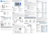
WIRING DIAGRAMS SCHEMI DI CONNESSIONE
3 phase connection with or without neutral
P01.08 = L1-L2-L3-N or L1-L2-L3
AUX SUPPLY
A1 I1
S2
A2
VOLTAGE
V1 VNV2 V3 S1
I3
I2
CURRENT
S1 S2 S1 S2
110...250VDC
100...240VAC
N
L2
L3
L1
TA1
D
TA2
O
TA3
A
L
+
---
2 phase connection
P01.08 = L1-N-L2
AUX SUPPLY
S2
I1
VOLTAGE
V1 VNV3V2 S1
I2
CURRENT
S1 S2
I3
S2S1
L2
N
L1
TA1
O
D
A
TA2
L
A1
--
A2
+
-
110...250VDC
100...240VAC
Single-phase connection
P01.08 = L1-N
D
AUX SUPPLY
N
I3
I2I1
VOLTAGE CURRENT
S2V1 VNV2 V3 S1 S1 S2 S1 S2
L1
TA1
O
A
L
A2A1
---
+
110...250VDC
100...240VAC
Balanced 3-phase connection with or without neutral
P01.08 = L1-L2-L3-N-BIL or L1-L2-L3-BIL
V2
VOLTAGE
L1
--
A1
AUX SUPPLY
-
A2
+
V1
N
L2
L3
S2
I1
V3 VN S1 S2
I2
I3
CURRENT
S2S1 S1
D
L
A
O
TA1
110...250VDC
100...240VAC
ARON connection 3 phase without neutral
P01.08 = L1-L2-L3
AUX SUPPLY
L2
L3
L1
A
I1
S2
VOLTAGE
V1 VNV2 V3 S1
I2
CURRENT
S1 S2
I3
S1 S2
D
TA1
TA2
L
O
A2A1
---
+
110...250VDC
100...240VAC
ARON connection 3 phase without neutral
P01.08 = L1-L2-L3
TA1
AUX SUPPLY
L2
L3
L1
S2
I1
VOLTAGE
V1 VNV3V2 S1
I2
I3
CURRENT
S1 S2 S2S1
A
TA3
D
L
O
--
A1
+
-
A2
110...250VDC
100...240VAC
3 phase connection with neutral via VT
Set P01.05, P01.06 and P01.07
P01.08 = L1-L2-L3-N
+
---
V2
VOLTAGE
L2
A2A1
AUX SUPPLY
N
L3
V1
L1
L
TA2
TA3
S2
I2
I3
I1
CURRENT
V3 VN S1 S2 S2S1 S1
A
O
D
TA1
TV
110...250VDC
100...240VAC
3 phase connection without neutral via VT
Set P01.05, P01.06 and P01.07
P01.08 = L1-L2-L3
CURRENT
AUX SUPPLY
A1
VOLTAGE
A2 I1 I2
L1
L3
L2
VNV1 V2 V3
TV
S1 S2 S1 S2
TA1
TA2
I3
S1 S2
TA3
O
D
A
L
---
+
110...250VDC
100...240VAC
NOTES
1. Recommended fuses:
Aux supply and measure inputs voltage: 1Amp. fast
2. S2 terminals are internally interconnected.
NOTE
1. Fusibili raccomandati:
Alimentazione ausiliaria e ingresso misura tensione: 1Amp rapido
2. I morsetti S2 sono internamente connessi fra di loro
Connessione trifase con o senza neutro
P01.08 = L1-L2-L3-N o L1-L2-L3
Connessione bifase
P01.08 = L1-N-L2
Connessione monofase
P01.08 = L1-N
Connessione trifase bilanciata con o senza neutro
P01.08 = L1-L2-L3-N-BIL o L1-L2-L3-BIL
Connessione ARON 3 fasi senza neutro
P01.08 = L1-L2-L3
Connessione ARON 3 fasi senza neutro
P01.08 = L1-L2-L3
Connessione trifase con neutro mediante TV
Impostare P01.05, P01.06 e P01.07
P01.08 = L1-L2-L3-N
Connessione trifase senza neutro mediante TV
Impostare P01.05, P01.06 e P01.07
P01.08 = L1-L2-L3

I386 GB I 10 13 31100190
12
PC- DMED320 CONNECTION THROUGH RS485 INTERFACE CONNESSIONE PC-DMED320.. MEDIANTE INTERFACCIA RS485
DMG320
PX1
PX1
Device addresses n° 1-30
PX1
TR SGAB
DMG320
Device addresses n° 31-60
up to 255 devices
Repeat this wiring diagram
Set as repeaterSet as repeater
DMG320 n°1
SG
DMG320 n°31
ABTR
RS485
RS485
PX1
PC
SGABTR SGABTR
Max 1200m
Cable
51C4
Interface converter
RS232/485
Max 1200m Max 1200m
Interface converter
RS232/485
Interface converter
RS232/485
Interface converter
RS232/485
PC
Cable
51C4
RS485 RS485
TR SGAB TR SGAB TR SGAB TR SGAB TR SGAB TR SGAB
TERMINALS POSITION AND MECHANICAL DIMENSIONS DISPOSIZIONE MORSETTI E DIMENSIONI MECCANICHE
Order code Description Wt [kg]
4PX1 RS-232/RS-485 opto-isolated converter drive 0.600
220…240VAC supply
51C4 PC- RS-232/RS-485 converter drive connection cable, 0.147
1.8 meters long
RS-232/RS-485 opto-isolated converter drive, 38,400 Baud-rate max, automatic or manual TRANSMIT line supervision, 220…240VAC ±10%
supply (possible 110…120VAC on request).
REMOTE CONTROL
Codici ordinazione Descrizione Peso [kg]
4PX1 Convertitore RS232/RS-485 galvanicamente isolato alimentatore 0,600
220…240VAC
51C4 Cavo di connessione PC- Convertitore RS232/RS-485 0,147
lunghezza 1,80 metri
Convertitore da tavolo RS232/RS-485 optoisolato, 38.400 Baud-rate max, gestione automatica o manuale della linea di TRASMIT,
alimentazione 220…240VAC ±10% oppure 110…120Vac a richiesta.
CONTROLLO REMOTO
S2
TR
I1
S1
S2
S2
S1
I2
S1
I3
A2A1 V1 VNV2 V3
ABSG
72
90
45
58
43.7
5
/